- Page 1 and 2: Geometric Effects on Maximum Power
- Page 3 and 4: ABSTRACTNumerical simulations are c
- Page 5 and 6: 3.7 Absorbed Wave Power ...........
- Page 7 and 8: LIST OF FIGURESFigurePageFigure 1.1
- Page 9 and 10: NOMENCLATUREA=incident wave amplitu
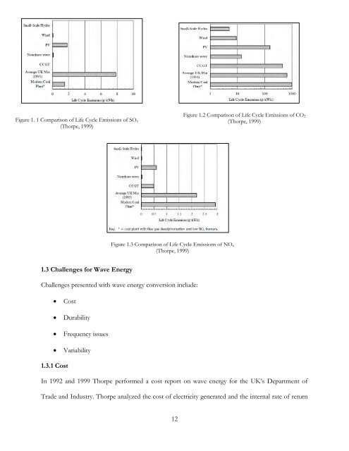
- Page 11: 1.2 Advantages of Wave EnergyAdvant
- Page 15 and 16: pollution would occur from hydrauli
- Page 17 and 18: Figure 1. 7 Average Annual Wave Pow
- Page 19 and 20: Backer (2009) numerically and exper
- Page 21 and 22: CHAPTER 2. WAVE ENERGY CONVERSION D
- Page 23 and 24: 2.3 OrientationOrientation is defin
- Page 25 and 26: Figure 2.4 Oscillating Water Column
- Page 27 and 28: 2.5 Reference PointMeans of reactio
- Page 29 and 30: Linear GeneratorTurbineRotary Gener
- Page 31 and 32: Table 2. 1 WEC ClassificationsDevic
- Page 33 and 34: 33P.T.O.MooringReferencePointOperat
- Page 35 and 36: CHAPTER 3. THEORY AND GOVERNING EQU
- Page 37 and 38: F(x,z,t) z 0DFDtFt u F 0 0 (4
- Page 39 and 40: in ni(13)on S for i=1, 3in( r n)i3
- Page 41 and 42: I iAg e ekz i( kx t)(30)cosh( k(z
- Page 44 and 45: where ijkis the permutation symbol.
- Page 46 and 47: Mw k ieitS( D I) ijkrinjdS(46)3.3.3
- Page 48 and 49: Due to Kirchhoff decomposition, rec
- Page 50 and 51: TE KE PE 20L Asin(kx) 1 2(61)dV d
- Page 52 and 53: P I Iw dS (70)tnSIf the column
- Page 54 and 55: 221 2P gA C(77)max g2 3.8 Maximum
- Page 56 and 57: 4.2 AQWA Modeling ProcedureThe user
- Page 58 and 59: : Local data has changed, and the c
- Page 60 and 61: Figure 4. 5 Drawing in Design Modul
- Page 62 and 63:
12. Delete all lines inside the cur
- Page 64 and 65:
22. Edit the details of the slice u
- Page 66 and 67:
Figure 4. 15 Details of the Part7.
- Page 68 and 69:
Figure 4. 17 Details of the Mesh4.2
- Page 70 and 71:
Figure 4. 21 Detials of the Wave Di
- Page 72 and 73:
5. Highlight Diffraction + Froude-K
- Page 74 and 75:
Table 4.1 Body Dimensions for Numer
- Page 76 and 77:
concavity from concave down to conc
- Page 78 and 79:
Figure 4. 29 Maximum Power Absorpti
- Page 80 and 81:
Table 4. 3 Numerical ResultsBodyNo.
- Page 82 and 83:
BodyNo.Bodyλ atT=2.1λ atT=1.0λ a
- Page 84 and 85:
WAVEFigure 5. 1 Body Faces Wave Mak
- Page 86 and 87:
The body connects to the aluminum p
- Page 88 and 89:
also allowed for flexibility in cre
- Page 90 and 91:
AB1 23 4 5 6 7CD8 9 10 11EFigure 5.
- Page 92 and 93:
and minimum voltage range of the DA
- Page 94 and 95:
Figure 5. 11 Deleting a Step from L
- Page 96 and 97:
Figure 5. 14 Recording Options, Sig
- Page 98 and 99:
Figure 5. 17 Right-mouse Click on t
- Page 100 and 101:
Zero-OffsetThe Zero-Offset step rem
- Page 102 and 103:
Figure 5. 24 Filter Step Set-up, Co
- Page 104 and 105:
5.6 Data ProcessingFigure 5. 26 Wav
- Page 106 and 107:
5.8 Experimental DiscussionAs menti
- Page 108 and 109:
5.8.3 Suggestions for Future Resear
- Page 110 and 111:
110ikxxRekddzkgkn )cosh())(cosh(,
- Page 112 and 113:
Proof M ij and B ij are Symmetric T
- Page 114 and 115:
BIBILIOGRAPHYANSYS. (n.d.). ANSYS A
- Page 116:
Trust, C. (2011). Capital, Operatin