MS Thesis R. Hager - Hawaii National Marine Renewable Energy ...
MS Thesis R. Hager - Hawaii National Marine Renewable Energy ...
MS Thesis R. Hager - Hawaii National Marine Renewable Energy ...
- No tags were found...
You also want an ePaper? Increase the reach of your titles
YUMPU automatically turns print PDFs into web optimized ePapers that Google loves.
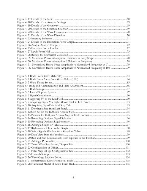
Figure 4. 17 Details of the Mesh ................................................................................................................... 68Figure 4. 18 Details of the Analysis Settings ................................................................................................ 69Figure 4. 19 Details of the Geometry ........................................................................................................... 69Figure 4. 20 Details of the Structure Selection ............................................................................................ 69Figure 4. 22 Details of the Wave Frequencies ............................................................................................. 70Figure 4. 21 Detials of the Wave Direction ................................................................................................. 70Figure 4. 23 Inserting Solutions ..................................................................................................................... 71Figure 4. 24 Details of the Excitation Force Graph ................................................................................... 71Figure 4. 26 Analysis System Complete ........................................................................................................ 72Figure 4. 25 Exciation Force Results ............................................................................................................ 72Figure 4. 27 Lewis Form Hull ........................................................................................................................ 73Figure 4. 28 Results for Numerical Validation ............................................................................................ 75Figure 4. 29 Maximum Power Absorption Efficiency vs Body Shape ................................................... 78Figure 4. 30 Maximum Power Absorption Efficiency vs Frequency ...................................................... 78Figure 4. 31 Normalized Heave Force Amplitude vs Normalized Frequency at 0 ◦ .............................. 79Figure 4. 32 Normalized Heave Force Amplitude vs Normalized Frequency at 180 ◦ ......................... 79Figure 5. 1 Body Faces Wave Maker (0 ○ ) ..................................................................................................... 84Figure 5. 2 Body Faces Away from Wave Maker (180 ○ ) ............................................................................ 84Figure 5. 3 Wave Flume Set-up ...................................................................................................................... 85Figure 5.4 Body and Aluminum Rod and Plate Attachment ..................................................................... 86Figure 5. 5 Body Set-up ................................................................................................................................... 87Figure 5. 6 Lateral Support System ............................................................................................................... 87Figure 5. 7 Signal Conditioner ....................................................................................................................... 90Figure 5. 8 Applying 5V to the Load Cell .................................................................................................... 90Figure 5. 9 Acquiring Signal Via Right-Mouse Click in Left Panel .......................................................... 93Figure 5. 10 Acquiring Signal Via Add Step Tab ........................................................................................ 93Figure 5. 11 Deleting a Step from Left Panel .............................................................................................. 94Figure 5. 12 Step Set-up for DAQmx Acquire Step ................................................................................... 95Figure 5. 13 Preview for DAQmx Acquire Step in Table Format ........................................................... 95Figure 5. 14 Recording Options, Signal Selection ....................................................................................... 96Figure 5. 15 Recording Options, Log Summary ......................................................................................... 96Figure 5. 16 Adding a Graph or Table .......................................................................................................... 97Figure 5. 17 Right-mouse Click on the Graph ............................................................................................ 98Figure 5. 18 Select Signals Window for a Graph or Table ........................................................................ 98Figure 5. 19 Data View from the Toolbar .................................................................................................... 99Figure 5. 20 Run and Run Continuously from Operate in the Toolbar .................................................. 99Figure 5. 21 Adding a Process Step ............................................................................................................ 100Figure 5. 22 Zero Offset Step Set-up/Output Tab ................................................................................. 100Figure 5. 23 Configuration of Offset ......................................................................................................... 101Figure 5. 24 Filter Step Set-up, Configuration Tab .................................................................................. 102Figure 5. 25 Formula Set-up ........................................................................................................................ 103Figure 5. 26 Wave Gage Labview Set-up .................................................................................................. 104Figure 5. 27 Experimental Lewis Form Hull Body .................................................................................. 105Figure 5. 28 Numerical Model of Lewis Form Hull ................................................................................ 1058


