- Page 1 and 2:
. c-o,.oy t:) ~3 J .-7I ~U~~T Snett
- Page 3 and 4:
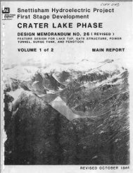
SYNOPSISThe Long Lake - Crater Lake
- Page 5 and 6:
LOCATION:SNETTISHAM PROJECT, ALASKA
- Page 7 and 8:
Maximum momentary head, ft(during l
- Page 9 and 10:
(3) Based on generation of 27.3 MW
- Page 11 and 12:
APPENDIX AGEOTECHNICAL DATAAlA2GEOM
- Page 13 and 14:
A. "AVERAGE" FAULT CONDITION.GEOMEC
- Page 15 and 16:
For the existing conditions the fol
- Page 17 and 18:
SUMMARY ."'OGHOLE Nv.N 93 61':' I S
- Page 19 and 20:
SUMMARY LOG N 93614 1 ~H~~T3 Of 3HO
- Page 21 and 22:
SUMMARY LOG95473H 0 LEN DH 99 9 160
- Page 23 and 24:
SUMMARY LOG N 95473 I SWFFT 4 OF 4H
- Page 25 and 26:
SUMMARY LOGHOLE NE9361186371Crater
- Page 27 and 28:
SUMMARY LOG N 93611 I SHEET 4 OF 4H
- Page 29 and 30:
SUMMARY LOGHOLE N DH 101 cont'd9411
- Page 31 and 32:
N 93.616 lSME£T 1 OF4SUMMARY LOGHO
- Page 33 and 34:
DEPTH OF HOLE9361686380DRILL OATES
- Page 35 and 36:
SUMMARY LOG I SHEF:T 1 OF' 4H 0 L E
- Page 37 and 38:
SUMMARY LOGHOLE NO.I N 9L271.~9 I S
- Page 39 and 40:
SWN\I~ARYLOGH 0 L E NO.DDH-10~I~N=-
- Page 41 and 42:
LOGH 0 L E NO. DDH-lO~ HE N;;--,,"9
- Page 43 and 44:
SUMMARY LOGHOLE NO.DDH-IO~PROJECT S
- Page 45 and 46:
SUM~AR,(LOG\ N ac.~l~ I SHEET 2 OF,
- Page 47 and 48:
SU,'t1:--,lARY LOG I N 0)':'1 ,c,.
- Page 49 and 50:
SU~AMARYLOGHOLE NO.N 95159. I SHF E
- Page 51 and 52:
SUMMARY LOG N 951S9. 1 SHct=:T 4 OF
- Page 53 and 54:
SU:\,1:--.4ARY LOGH 0 L E NO.DIJH-1
- Page 55 and 56:
LOGHOLE NO. DCii-107 I SUR,rACe: EL
- Page 57 and 58:
,S UMMARY .~OG N 93451 r SHEff 1 Qf
- Page 59 and 60:
SUMMARY LOGH 0 L-E NO. DDH-I09~NIiI
- Page 61 and 62:
_liUMMARY lOG N 93685 1 ~W~F'T 3 OF
- Page 63 and 64:
SUMMARY LOGH-O-L E NO.DDH-110N 9354
- Page 65 and 66:
$UMMARY I~~GK 93729.8HOLE N . DH-ll
- Page 67 and 68:
N 93729.8~UMM~RY Ib~G.. OL;- N . Dh
- Page 69 and 70:
HOLEI PROJEC_,- e"WLa,. COIoIP.~ ~F
- Page 71 and 72:
,~UMMARY IbOGN Q
- Page 73 and 74:
Il,UMMARV ,~~G N 93767.6I OLE N . D
- Page 75 and 76:
[ ~UMMARY LOG N 93767.6OLE NO. rlH
- Page 77 and 78:
~UMMARV I'cfGN q17fi7 fiOLE N DH-1l
- Page 79 and 80:
SUMMARY .L;PG N 93773. 3 SH~~T 1 OF
- Page 81 and 82:
SUMMARY ,,,,00N 93773. 3 SM~~T 30F
- Page 83 and 84:
~~UMMARY 1'o~GI PAO::C~ ("tee ",.N
- Page 85 and 86:
ISUMMARY LOGHOLE N . DH-1l4PROJECT
- Page 87 and 88:
93731.086934.0PROJ E C TORILL DATES
- Page 89 and 90:
SUMMARY LOG 93731.0HOLE N . 86934.0
- Page 91 and 92:
SUMMARY I~OGN 95300.4SHEET 1 Of 7 j
- Page 93 and 94:
! SUMMARY.",OG N 95300.4 SH£~T1 Of
- Page 95 and 96:
SUMMARY LOG- N QC;1nn. 4HOLE NO. DH
- Page 97 and 98:
SUMMARY I~OG N Q'i1nO.4 SH£~T 7 OF
- Page 99 and 100:
APPENDIX BlHYDRAULIC DESIGN OF RECO
- Page 101 and 102:
PARAGRAPHC. Hydraulic Losses in Mac
- Page 103 and 104:
APPENDIX B1HYDRAULIC DESIGN OF RECO
- Page 105 and 106:
Various plates which appear in both
- Page 107 and 108:
C. Power Tunnel. The power tunnel i
- Page 109 and 110:
The primary and secondary rock trap
- Page 111 and 112:
G. Gate Structure Transition.(1) Si
- Page 113 and 114:
quantity of water in the gate struc
- Page 115 and 116:
will be approximately 12.5 ft and o
- Page 117 and 118:
Figure 7 in appendix B2 contains a
- Page 119 and 120:
accompaning cross-sectional areas o
- Page 121 and 122:
(3) Losses in Steel Penstock - Fric
- Page 123 and 124:
the type of pipe to be used at Crat
- Page 125 and 126:
unlined tunnel was 0.187 ft. Simila
- Page 127 and 128:
1.04 HYDRAULIC TRANSIENTSA. Operati
- Page 129 and 130:
Representat i ves of HEOB and OCE r
- Page 131 and 132:
nominal diameter and 27.9 percent f
- Page 133 and 134:
I. Computer Models.(1) Computer Pro
- Page 135 and 136:
increase the Polar Moment of Inerti
- Page 137 and 138:
"WHAMO" was used for the run and re
- Page 139 and 140:
surge tank (reject condition) is 10
- Page 141 and 142:
a surge tank approximately 350 ft h
- Page 143 and 144:
1.05 LAKE TAPA. Genera 1. The 1 ake
- Page 145 and 146:
Trashrack ConditionZero clogging25%
- Page 147 and 148:
plug, approximate sta 10+50 and at
- Page 149 and 150:
the blast pressure recorded at cell
- Page 151 and 152:
REFERENCES1. Mattimoc, J. J., Tinne
- Page 153 and 154:
APPENDIX B2SUPPORTING TECHNICAL DAT
- Page 155 and 156:
eUN.(Fl.). ,~f···~"'. '"".f1~~_.
- Page 157 and 158:
'.1":' ..."'..: ..:.........iI\~~fr
- Page 159 and 160:
COMP .~ > ,;--C H K 0 • ~,-,,,,-\
- Page 161 and 162:
C OMP. '3N3""CHKD. ___SUBJECTU.S. A
- Page 163 and 164:
COMP. ;IN:rCHKD. __ _SUBJECTC.IGA T
- Page 165 and 166:
CaMP. In::;:CHKD. ___ _SUBJECTU.S.
- Page 167 and 168:
JI~COMPoCHKD. ___SUB~IECTC I( A Te(
- Page 169 and 170:
·COMP. :1Nd~, U.S. ARMY ENGINEER D
- Page 171 and 172:
'COMPo )N"TCHKD. __ _SUBJECTU.S. AR
- Page 173 and 174:
COMPoC H KD.:r~:ru.s. ARMY ENGINEER
- Page 175 and 176:
(C OMP. :r IV 3'CHKD. J .,..1SUBJEC
- Page 177 and 178:
C OMP. ::r NS"CHKD.J 101SUBJECT3LiU
- Page 179 and 180:
46 13231~ t l TIr!!f I..I' ,;I ' 'j
- Page 181 and 182:
COM P. JIv J u . S. ARM YEN GIN E E
- Page 183 and 184:
COMP.lf!::C H K D •.::.YuleIDo/L.
- Page 185 and 186:
COMPo 0N"S'""CHKD •• J WJ"JU.S.
- Page 187 and 188:
U.S. ARMY ENGINEER DISTRICT, ALASKA
- Page 189 and 190:
COIo4P.CHKD.U.S. ARMY ENGINEER DIST
- Page 191 and 192:
COMPoCHKD.,r., '........,.~S U!:!..
- Page 193 and 194:
COMPo ;fA/if "CHKO.-r- u.s. ARMY EN
- Page 195 and 196:
COMP.CHkO.U.S. ARMY ENGINEER DISTRI
- Page 197 and 198:
COMP.CHKO.SUBJECTU.S. ARMY ENGINEER
- Page 199 and 200:
~~=::ySUBJECTU.S. ARMY ENGINEER DIS
- Page 201 and 202:
NPA FORM 16Ba (Rev.) Previous editi
- Page 203 and 204: i•COMPo StJ\CHKD. JJSUBJECTZ/ 1?t
- Page 205 and 206: COMPo ,)N)CHKD. 9"~SlIBJECTHU.S. AR
- Page 207 and 208: NPA FORM 168a (Rev.) Previous editi
- Page 209 and 210: "':'\.CO~P.~CHKD.~SUBJECTU.S. ARMY
- Page 211 and 212: ~( \lAL..\)~S iC.E\\\M\1'\) (.cc-0s
- Page 213 and 214: -C OMP. \./ t..JCHJ(D._~_t~_"SUBJEC
- Page 215 and 216: ___ .___._~ ..-=..........__ ._+-__
- Page 217 and 218: ~UIII~::J•o•zo.,'"
- Page 219 and 220: 604·· FIUC • e893 FINI65COf41)
- Page 221 and 222: 1 CRATER lA
- Page 223 and 224: lZ112Z DISPLAY ALL FINISHla3124 HIS
- Page 225 and 226: S4· rRIC .01S0 FINI~5 COMO 10 C10e
- Page 227 and 228: .DISCHRI2CE. CO£.FFICIGNT vs VALVE
- Page 229 and 230: SA CPLUS .el C~1NUS .el rI~I65 CONO
- Page 231 and 232: 1'~,~~TER LAKE. Sl'fETTISHM. HYDRAU
- Page 233 and 234: ~!;:t:-~·.; ..'!;'~totoJ)l.14M PIa
- Page 235 and 236: )0.40.5~IT' I" THiI "'lIee C .....
- Page 237 and 238: sf· C· PLOTTIMG REQUESTS&a,1fLO.T
- Page 239 and 240: ········· .. ·· .... ·
- Page 241 and 242: .... D.~.~ T.altcTtOtt II TJl II'UI
- Page 243 and 244: 'IIEL~CT'ltC6 ()veH .,}{)(L~ue TA ~
- Page 245 and 246: \C'iCfilB1L L.A-1L-l:5'"GU3C-TelG "
- Page 247 and 248: APPENDIX B3HYDRAULIC DESIGN OF ALTE
- Page 249 and 250: The power tunne 1 entrance wi 11 be
- Page 251 and 252: B. Losses in the Power Tunnel.(1) U
- Page 253: 3.04 SURGE TANK.A. Operating Requir
- Page 257 and 258: (2) Condition A - Maximum surge for
- Page 259 and 260: I. Stability Routings.To de~onstrat
- Page 261 and 262: 3.05 PRESSURE AND SPEED REGULATION.
- Page 263 and 264: Maximum water hammer pressure gradi
- Page 265 and 266: APPENDIX B4HYDRAULIC DESIGN OF ALTE
- Page 267 and 268: 4.02 DESCRIPTION OF THE POWER CONDU
- Page 269 and 270: 4.04 AIR CHAMBER SURGE TANK.A. Oper
- Page 271 and 272: 12-ft diameter power tunnel with a
- Page 273 and 274: Asc = Critical (horizontal) area of
- Page 275 and 276: CRITICAL AIR VOLUMES BASED ON SVEE
- Page 277 and 278: Since the air volume required in th
- Page 279 and 280: The results of the rejection and de
- Page 281 and 282: from these gauges will be converted
- Page 283 and 284: Air 1 eakage through the rock is go
- Page 285 and 286: needed for normal power production
- Page 287 and 288: 4.06 PRESSURE AND SPEED REGULATIONA
- Page 289 and 290: 4.07 INTERNAL CONDUIT PRESSURESA. G
- Page 291 and 292: hammer values. Water ham~er and spe
- Page 293 and 294: 16. U.S. Dept. of Interior, "Design
- Page 295 and 296: 'I ,j:' 1 ! .~ .... ; : r :-:; I r
- Page 297 and 298: 1. Jistances ~f j,10,~nrl l~ tt h~t
- Page 299 and 300: TABLE IMAXIMUM PRESSURE ANDSPEED RI
- Page 301 and 302: 17()D').~~-----; !CSURMSUR(Chaudhry
- Page 303 and 304: 5 4 3 21 0occBB-----------Aa..::;VI
- Page 305 and 306:
5I 4 I 32DESIGN SURGE TANK DIA. = 1
- Page 307 and 308:
D5 I4 I 3 2 1 1THIS TANK IS LESS TH
- Page 309 and 310:
5 I4 I 3 2 11---_._---0CRATER LAKE#
- Page 311 and 312:
c---54 : 3 2 11D1. SEE PLATE B2 FOR
- Page 313 and 314:
5 I 4 3 2 11----0 1. SEE PLATE B2 F
- Page 315 and 316:
5 I4 [ 3 2 !1DEUtICRATER LAKE, SNET
- Page 317 and 318:
5 l41...j3 2,1r0--£tEV'"1U4S.113e.
- Page 319 and 320:
CORPS OF ENGINEERSU. S. ARMY1040 f-
- Page 321 and 322:
\ \ /A~1-- I.- -- QUIESCENT' 1 I514
- Page 323 and 324:
CORPS OF ENGINEERSU. S. ARMY~'" 00~
- Page 325 and 326:
5 4 I 3 I 2 1 II THS TANK IS STABLE
- Page 327 and 328:
-DC 9505 I 4 I 3 I 2 1I DESIGN TANK
- Page 329 and 330:
APPENDIX CPENSTOCK DESIGNC1C2ANALYS
- Page 331 and 332:
e cANALYSIS OF CONFINED PENSTOCKS.
- Page 333 and 334:
-Rcdr.op a vertical l:ine to the ab
- Page 335 and 336:
liner • Longitudinal members and.
- Page 337 and 338:
- ~",/APPENDIX C2STRESS ANALYSIS OF
- Page 339 and 340:
.' '", ,_" - _. ' •• :~"~';:',~
- Page 341 and 342:
'. ~~'. L1 zmuslbe'es//mCl-led.:" ~
- Page 343 and 344:
. ,c'R- II51-2 - 87"LlI -I- ~2 ,; O
- Page 345 and 346:
CONCRFTEDEFORMATION...--'Ir---Difre
- Page 347 and 348:
srra/n,- ....Bdt"sp/ac6'mel7tDC-r ,
- Page 349 and 350:
- . .
- Page 351:
7. E: ..':·"·tillTCES~ .Wa.ter Po


