Raman Spectroscopy of nanomaterials - institut de chimie et des ...
Raman Spectroscopy of nanomaterials - institut de chimie et des ...
Raman Spectroscopy of nanomaterials - institut de chimie et des ...

Create successful ePaper yourself
Turn your PDF publications into a flip-book with our unique Google optimized e-Paper software.
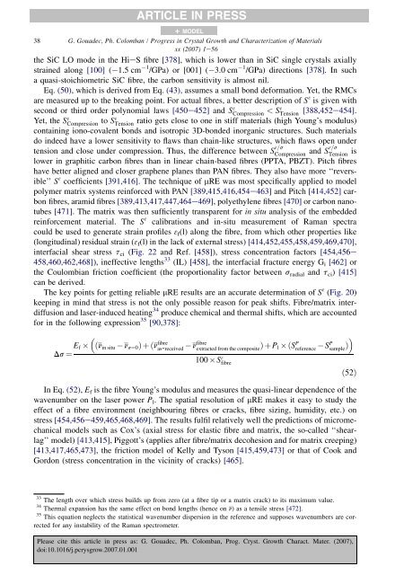
38 G. Goua<strong>de</strong>c, Ph. Colomban / Progress in Crystal Growth and Characterization <strong>of</strong> Materialsxx (2007) 1e56the SiC LO mo<strong>de</strong> in the HieS fibre [378], which is lower than in SiC single crystals axiallystrained along [100] ( 1.5 cm 1 /GPa) or [001] ( 3.0 cm 1 /GPa) directions [378]. In sucha quasi-stoichiom<strong>et</strong>ric SiC fibre, the carbon sensitivity is almost nil.Eq. (50), which is <strong>de</strong>rived from Eq. (43), assumes a small bond <strong>de</strong>formation. Y<strong>et</strong>, the RMCsare measured up to the breaking point. For actual fibres, a b<strong>et</strong>ter <strong>de</strong>scription <strong>of</strong> S 3 is given withsecond or third or<strong>de</strong>r polynomial laws [450e452] and S 3 Compression < S3 Tension [388,452e454].Y<strong>et</strong>, the S 3 Compression to S3 Tension ratio g<strong>et</strong>s close to one in stiff materials (high Young’s modulus)containing iono-covalent bonds and isotropic 3D-bon<strong>de</strong>d inorganic structures. Such materialsdo in<strong>de</strong>ed have a lower sensitivity to flaws than chain-like structures, which flaws open un<strong>de</strong>rtension and close un<strong>de</strong>r compression. Thus, the difference b<strong>et</strong>ween S 3=sCompressionand S3=sTension islower in graphitic carbon fibres than in linear chain-based fibres (PPTA, PBZT). Pitch fibreshave b<strong>et</strong>ter aligned and closer graphene planes than PAN fibres. They also have more ‘‘reversible’’S 3 coefficients [391,416]. The technique <strong>of</strong> mRE was most specifically applied to mo<strong>de</strong>lpolymer matrix systems reinforced with PAN [389,415,416,454e463] and Pitch [414,452] carbonfibres, aramid fibres [389,413,417,447,464e469], poly<strong>et</strong>hylene fibres [470] or carbon nanotubes[471]. The matrix was then sufficiently transparent for in situ analysis <strong>of</strong> the embed<strong>de</strong>dreinforcement material. The S 3 calibrations and in-situ measurement <strong>of</strong> <strong>Raman</strong> spectracould be used to generate strain pr<strong>of</strong>iles 3 f (l) along the fibre, from which other properties like(longitudinal) residual strain (3 f (l) in the lack <strong>of</strong> external stress) [414,452,455,458,459,469,470],interfacial shear stress t ci (Fig. 22 and Ref. [458]), stress concentration factors [454,456e458,460,462,468]), ineffective lengths 33 (IL) [458], the interfacial fracture energy G i [462] orthe Coulombian friction coefficient (the proportionality factor b<strong>et</strong>ween s radial and t ci ) [415]can be <strong>de</strong>rived.The key points for g<strong>et</strong>ting reliable mRE results are an accurate <strong>de</strong>termination <strong>of</strong> S 3 (Fig. 20)keeping in mind that stress is not the only possible reason for peak shifts. Fibre/matrix interdiffusionand laser-induced heating 34 produce chemical and thermal shifts, which are accountedfor in the following expression 35 [90,378]:E f ðn in situDs ¼ARTICLE IN PRESSn s¼0 Þþðn fibreas-received+ MODELn fibreextracted from the composite ÞþP l ðS P reference100 S 3 fibreS P sample Þ In Eq. (52), E f is the fibre Young’s modulus and measures the quasi-linear <strong>de</strong>pen<strong>de</strong>nce <strong>of</strong> thewavenumber on the laser power P l . The spatial resolution <strong>of</strong> mRE makes it easy to study theeffect <strong>of</strong> a fibre environment (neighbouring fibres or cracks, fibre sizing, humidity, <strong>et</strong>c.) onstress [454,456e459,465,468,469]. The results fulfil relatively well the predictions <strong>of</strong> micromechanicalmo<strong>de</strong>ls such as Cox’s (axial stress for elastic fibre and matrix, the so-called ‘‘shearlag’’mo<strong>de</strong>l) [413,415], Piggott’s (applies after fibre/matrix <strong>de</strong>cohesion and for matrix creeping)[413,417,465,473], the friction mo<strong>de</strong>l <strong>of</strong> Kelly and Tyson [415,459,473] or that <strong>of</strong> Cook andGordon (stress concentration in the vicinity <strong>of</strong> cracks) [465].ð52Þ33 The length over which stress builds up from zero (at a fibre tip or a matrix crack) to its maximum value.34 Thermal expansion has the same effect on bond lengths (hence on n) as a tensile stress [472].35 This equation neglects the statistical wavenumber dispersion in the reference and supposes wavenumbers are correctedfor any instability <strong>of</strong> the <strong>Raman</strong> spectrom<strong>et</strong>er.Please cite this article in press as: G. Goua<strong>de</strong>c, Ph. Colomban, Prog. Cryst. Growth Charact. Mater. (2007),doi:10.1016/j.pcrysgrow.2007.01.001