- Page 3:
COMMUNICATIONS,RADAR ANDELECTRONICW
- Page 7:
Content,6.3 Types of Communications
- Page 10 and 11:
xContents16.1.2 EMC Issues 26616.1.
- Page 12 and 13:
xiiContents20 Summary and Conclusio
- Page 14 and 15:
xivPrefaceI have provided some refe
- Page 16 and 17:
",iDiplexerdBddBiOEMOFDMEDownlinkDR
- Page 18 and 19:
xviiiGlos&aryNFDNSAOPOPTEMPOORE ATO
- Page 21:
Part OneBasic Theory
- Page 24 and 25:
4 CommunicatIOns, Radar and Electro
- Page 27 and 28:
[ ntroductlon 7......Figure 1.4 A t
- Page 29 and 30:
Introduction 9IIIFigure 1.6 A naval
- Page 31 and 32:
Introduction 11• In many cases, p
- Page 33 and 34:
Introduction 13Typical equipment th
- Page 35 and 36:
Introduction 15into a suitable digi
- Page 37 and 38:
-
- Page 39 and 40:
Introduction 19For the communicatio
- Page 41 and 42:
Introduction21Table 1.5Antenna cOlT
- Page 43 and 44:
Introduction23(a) Clear radio line
- Page 45 and 46:
--Introduction2SFor microwave frequ
- Page 47 and 48:
2Management of the Radio Spectrum2.
- Page 49 and 50:
Management of the Radio Spectrum29I
- Page 51 and 52:
Management of the Radio Spectrum 31
- Page 53 and 54:
Management of the Radio Spectrum33H
- Page 55 and 56:
Management of the Radio Spectrum 35
- Page 57 and 58:
Management of the Radio Spectrum 37
- Page 59 and 60:
Management of the Radio Spectrum39\
- Page 61 and 62:
Management of the RadIO Spectrum 41
- Page 63:
Management of the Radio Spectrum-13
- Page 66 and 67:
46CommUnICatIOns, Radar and Electro
- Page 68 and 69:
48 Communications, Radar and Electr
- Page 70 and 71:
!I.1II,soCommunications, Radar and
- Page 72 and 73:
52 CommunIcations, Radar and Electr
- Page 74 and 75:
54 COIllIllUIlICatiOnS, Radar and E
- Page 76 and 77:
56 Communications, Radar and Electr
- Page 78 and 79:
58 Communications, Radar and Electr
- Page 80 and 81:
..60(f)(f)o-lCommunications, Radar
- Page 82 and 83:
-----62Communications, Radar and El
- Page 85 and 86:
4Radio Links in the Presenceof Nois
- Page 87 and 88:
Radio Links in the Preence of Noise
- Page 89 and 90:
Radio Links in the Presence of Nois
- Page 91 and 92:
Radio Links in the Presence of Nois
- Page 93 and 94:
Radio Links in the Presence of Nois
- Page 95 and 96:
Radio Links in the Presence of Nois
- Page 97:
Radio Links in the Presence of Nois
- Page 100 and 101:
80 Communications, Radar and Electr
- Page 102 and 103:
82 Communications, Radar and Electr
- Page 104 and 105:
X-lFigure 5.4 Illustration of energ
- Page 106 and 107:
---86 CommunicatIOns, Radar and Ele
- Page 108 and 109:
88 Communications, Radar and Electr
- Page 110 and 111:
90 Communications, Radar and Electr
- Page 112 and 113:
92 Communications, Radar and Electr
- Page 114 and 115:
94 Communications, Radar and Electr
- Page 116 and 117:
96 Communications, Radar and Electr
- Page 118 and 119:
1'1,----__ 1·_ >FrequencyDetected
- Page 120 and 121:
100 Communications, Radar and Elect
- Page 122 and 123:
Radar and Radar Jamming103-- -- --
- Page 124 and 125:
Radar and Radar Jamming105...... ..
- Page 126 and 127:
108Communications, Radar and Electr
- Page 128 and 129:
Radar and Radar Jamming109Vertical
- Page 130 and 131:
Radar and Radar Jamming111Displayte
- Page 132 and 133:
Radar and Radar Jammmg113ill;;:0D-0
- Page 134 and 135:
Radar and Radar Jamming 115oPhase +
- Page 136 and 137:
Radar and Radar Jamming 117Correlat
- Page 138 and 139:
Radar and Radar Jamming119Displayte
- Page 140 and 141:
Radar and Radar Jamming 121shows th
- Page 142 and 143:
Radar and Radar Jamming 123Advancin
- Page 144 and 145:
Radar and Radar Jamming125Basebands
- Page 146 and 147:
Radar and Radar Jammmg 127aircraft,
- Page 148 and 149:
Radar and Radar Jammmg12')j r .)11'
- Page 150 and 151:
Radar and Radar Jamming131(a)(c)c:C
- Page 152:
Radar and Radar Jamming 1337.5 Rada
- Page 155 and 156:
136 Communications, Radar and Elect
- Page 157 and 158:
138 Communications, Radar and Elect
- Page 159 and 160:
140 Communications, Radar and Elect
- Page 161 and 162:
142 Communications, Radar and Elect
- Page 163 and 164:
144 Communications, Radar and Elect
- Page 166 and 167:
9Predicting HF Radio9.1 Propagation
- Page 168 and 169:
Predicting HF Radio149Predicted sun
- Page 170 and 171:
Predicting HF Radio 151Range (km)Fi
- Page 172 and 173:
Predicting HF Radio153lOW. CM' '-'
- Page 174 and 175:
0.. iS·{)q'"0..o·..U1U1jJ .\R(PS
- Page 176 and 177:
Predicting HF Radio 157Remember tha
- Page 178 and 179:
10VHF to SHF Radio Prediction10.1 P
- Page 180 and 181:
..........................VHF to SH
- Page 182 and 183:
VHF to SHF Radio Prediction 163Sub-
- Page 184 and 185:
VHF to SHF Radio Prediction16530000
- Page 186 and 187:
VHF to SHF Radio Prediction167Figur
- Page 188 and 189:
VHF to SHF Radio Prediction169Fresn
- Page 190 and 191:
........VHF to SHF Radio Prediction
- Page 192 and 193:
144__VHF to SHF Radio Prediction 17
- Page 194 and 195:
VHF to SHF Radio Prediction175Trans
- Page 196 and 197:
VHF to SHF Radio Prediction177oTwo-
- Page 198 and 199:
VHF to SHF Radio Prediction 179With
- Page 200 and 201:
VHF to SHF Radio Prediction 181with
- Page 202 and 203:
VHF to SHF Radio Prediction 183is d
- Page 204 and 205:
VHF to SHF Radio PredictIOn 185Tabl
- Page 206 and 207:
VHF to SHF Radio Prediction187Table
- Page 208 and 209:
VHF to SHF Radio Prediction189Table
- Page 210 and 211:
11Data Requirements for RadioPredic
- Page 212 and 213:
opofJ?:l(0..ac.3(0;::.en8'>;?:l0.o'
- Page 214 and 215:
Data Requirements for Radio Predict
- Page 216 and 217:
u&::::0(1)..0c:3(1)::;:;;3'..,:::0'
- Page 218 and 219:
t)poS':;0(1).n::.3(1);aV>8'...,:;0p
- Page 220 and 221:
o0.>;::,:l(!).g:r.-;::,:lOJ0..5"-0r
- Page 222 and 223:
==Data Requirements for Radio Predi
- Page 224 and 225:
Data Requlrement for RddJO Prcdlctl
- Page 226 and 227:
Data Requirements for Radio Predict
- Page 228 and 229:
Data Requirements for Radio Predict
- Page 230 and 231:
Data Requirements for RadIO Predict
- Page 232 and 233:
Data Requirements for Radio Predict
- Page 234 and 235:
,I,Data Requirements for Radio Pred
- Page 236 and 237:
Data Requirements for Radio Predict
- Page 238:
Data Requirements for Radio Predict
- Page 241 and 242:
222 Communications, Radar and Elect
- Page 243 and 244:
224 Communications, Radar and Elect
- Page 245 and 246:
226 Communications, Radar and Elect
- Page 248 and 249:
13Planning Radio Networksfor Covera
- Page 250 and 251:
Planning Radio Networks for Coverag
- Page 252 and 253:
...Planning Radio Networks for Cove
- Page 254 and 255:
Planning Radio Networks for Coverag
- Page 256 and 257:
(((II/III/llcd)0):l:l:l[fQ:;00)9-:o
- Page 258 and 259:
Planning Radio Networks for Coverag
- Page 260 and 261:
Planning Radio Networks for Coverag
- Page 262 and 263:
Planntng RadIOetv.ork, for Covcrage
- Page 264 and 265:
Planning Radio Networks for Coverag
- Page 266 and 267:
14Interference Analysis14.1 Introdu
- Page 268 and 269:
Intelference Analysis249Received po
- Page 270 and 271:
Interference Analysis2510 ,-- -5-10
- Page 272 and 273:
Interference Analysis253Table 14.1
- Page 274:
Interference Analyls14.4 Different
- Page 277 and 278: 258 Communications, Radar and Elect
- Page 279 and 280: 260 Communications, Radar and Elect
- Page 281 and 282: 262CommunicatIOns, Radar and Electr
- Page 283 and 284: 264 CommuDlcation" Radar and Electr
- Page 285 and 286: 266 CommUnIcatIOns. Radar and Elect
- Page 287 and 288: 2M,------------- ------------ ---I:
- Page 289 and 290: 270 Communications, Radar and Elect
- Page 291 and 292: 272 Communications, Radar and Elect
- Page 293 and 294: 274 Communications, Radar and Elect
- Page 296 and 297: 278 Communications, Radar and Elect
- Page 298 and 299: 280 Communication5, Radar and Elect
- Page 300 and 301: 282CommunicatlOns, Radar and Electr
- Page 302 and 303: 2X4._---------_._--Despite these cl
- Page 304 and 305: 286 CommunicatlOns, Radar and Elect
- Page 306 and 307: 288 Communications, Radar and Elect
- Page 308 and 309: 290 Communications, Radar and Elect
- Page 310 and 311: 292 CommUniCatIOns, Radar and Elect
- Page 312 and 313: 294 Communicat ions. Rauar anu Elec
- Page 314 and 315: 296 CommUniCatIOns, Radar and Elect
- Page 316 and 317: 298Communications, Radar and Electr
- Page 318 and 319: 300 Communications, Radar and Elect
- Page 320 and 321: 302 CommUnICatIOns, Radar and Elect
- Page 322 and 323: (llll l Hlt (!I" tilL' \CIl\L' .Jll
- Page 324 and 325: 306 Communications, Radar and Elect
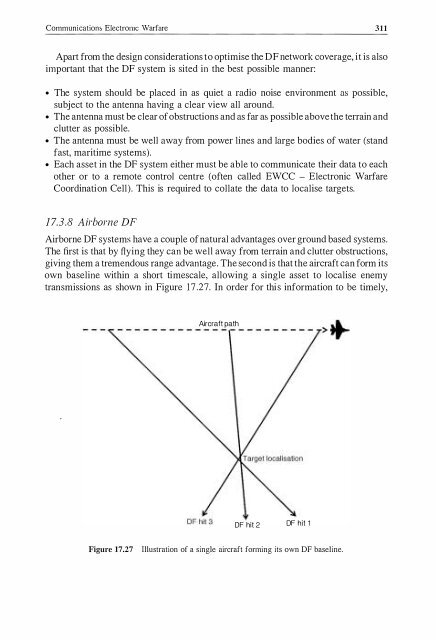
- Page 326 and 327: 308 Communications, Radar and Elect
- Page 330 and 331: 312 Communications, Radar and Elect
- Page 332 and 333: 314 Commumcation, Radar and Electro
- Page 334 and 335: 316 Communication, Radar and Electr
- Page 336 and 337: 318Communications, Radar and Electr
- Page 338 and 339: 320 Communications, Radar and Elect
- Page 340 and 341: 322Communications, Radar and Electr
- Page 342 and 343: 324 CommUI11Catlons, Radar and Elec
- Page 345 and 346: 18Non-CommunicationsElectronic Warf
- Page 347 and 348: Non-Communications Electronic Warfa
- Page 349 and 350: Non-Communication Electronic Warfar
- Page 351 and 352: ...Non-Communications Electronic Wa
- Page 353 and 354: )\;OIl-COllllllunlcatlOnplral radar
- Page 355 and 356: Non-CommunicatIons ElectronIc Warfa
- Page 357 and 358: Non-CommunIcations Electronic Warfa
- Page 359 and 360: Non-Communication,; Electrolllc War
- Page 361 and 362: Non-Communications Electronic Warfa
- Page 363 and 364: Non-CommunIcations Electronic Warfa
- Page 365 and 366: Non-CommunIcations ElectronIC Warfa
- Page 367 and 368: Non-Communications Electronic Warfa
- Page 369 and 370: Non-CommUnIcatIOns ElectronIc Warfa
- Page 371 and 372: 19Countering Radio-Controlled rEDs1
- Page 373 and 374: Coulltering RadlO-Colltrolled IEOsc
- Page 375 and 376: Countering Radio-Controlled IEDs 35
- Page 377 and 378: Countering Radio-Controlled rEDs359
- Page 379 and 380:
Countering Radio-Controlled IEDs 36
- Page 381:
Countering Radio-Controlled IEDs363
- Page 384 and 385:
COIllIllUlllcatlons. Radar and Elec
- Page 386 and 387:
368 Communications, Radar and Elect
- Page 388 and 389:
370 Communications, Radar and Elect
- Page 390 and 391:
372CllndllltJl'ily dnd !lemlJltl\'l
- Page 393 and 394:
Indexabsorption 53 , 160, 169-70act
- Page 395 and 396:
377cooperative 128cover 128deceptiv