- Page 2 and 3: San Luis Obispo CreekWaterway Manag
- Page 4 and 5: SECTION 4.0 HYDROLOGIC & HYDRAULIC
- Page 6 and 7: SECTION 8.0 DESIGN OF DRAINAGE PUMP
- Page 8 and 9: 11.12 Erosion Control Seeding......
- Page 10 and 11: DRAINAGE DESIGN MANUALFOR THECITY O
- Page 12 and 13: ôó1Ragged PointSan SimeonCambriaM
- Page 14 and 15: SECTION 2.0PROJECTS REQUIRING HYDRO
- Page 16 and 17: 3. or, is an individual development
- Page 18 and 19: • Geomorphic, Geotechnical and St
- Page 20 and 21: SECTION 3.0CORE REQUIREMENTS AND RE
- Page 22 and 23: elevations, and existing channel st
- Page 24 and 25: 1000 0 1000 Meters1 0 1 MilesCity L
- Page 26: N300 0 300 MetersLEGEND100-Year Flo
- Page 29 and 30: N300 0 300 MetersLEGEND100-Year Flo
- Page 31 and 32: N300 0 300 MetersLEGEND100-Year Flo
- Page 33 and 34: • All streets to be dedicated to
- Page 35 and 36: • A minimum setback of 15 m (50 f
- Page 37 and 38: 3.6.4 Preference for Vegetative and
- Page 39 and 40: compliance with the measures prescr
- Page 41 and 42: 4.1 Hydrologic Analysis4.1.1 Genera
- Page 43 and 44: Table 4-1Runoff CoefficientsHydrolo
- Page 45 and 46: Overland Flow TimeSLO Creek Phase I
- Page 47 and 48: Channel or Pipe Flow occurs where f
- Page 49 and 50: 45745766071176260955855860971166050
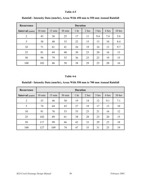
- Page 51: Table 4-3Rainfall - Intensity Data
- Page 55 and 56: Table 4-7Example Composite Runoff C
- Page 57 and 58: Table 4-9Example Rational Method Ru
- Page 59 and 60: developed. For minor waterways and
- Page 61 and 62: SECTION 5.0OPEN CHANNEL ANALYSIS AN
- Page 63 and 64: case, a Natural Channel may be modi
- Page 65 and 66: 5.2 Channel Design Flow Requirement
- Page 67 and 68: maintenance to maintain the design
- Page 69 and 70: The following guidelines should be
- Page 71 and 72: Channel PlanformDrainage Design Man
- Page 73 and 74: • Native vegetation shall be pres
- Page 75 and 76: Manning’s Roughness Values are pr
- Page 77 and 78: 6.1 GeneralSECTION 6.0ANALYSIS & DE
- Page 79 and 80: 6.3 Design ReferencesThe designer i
- Page 81 and 82: stream stabilization needs totaling
- Page 83 and 84: causes and modes of failure act tog
- Page 85 and 86: (permissive velocity) and/or bounda
- Page 87 and 88: Re-run the model after coding in th
- Page 89 and 90: Step 2 - Develop and Screen Alterna
- Page 91 and 92: Cost. The design must be cost effec
- Page 93 and 94: Step 3 - Develop Concept Plan and D
- Page 95 and 96: Legally it is up to the applicant t
- Page 97 and 98: e necessary, as well as other work
- Page 99 and 100: (0.6-0.9 m)(0.6-0.9 m)(152-203 mm)L
- Page 101 and 102: (1.2 m)(1.2 m)(12 mm to 51 mm)(1.5
- Page 103 and 104:
(0.9 m)(0.6 m x 0.6 m x 914 mm)(457
- Page 105 and 106:
(0.6 - 0.9 m)Vegetated GeogridDrain
- Page 107 and 108:
Planted Rip RapDrainage Design Manu
- Page 109 and 110:
A-JacksDrainage Design ManualCity &
- Page 111 and 112:
(1.5 m)(13 to 25 mm)(0.6 to 0.9 m)R
- Page 113 and 114:
(13 - 25 mm)(0.6 to 0.9 m)Planted G
- Page 115 and 116:
(2.4 m)(2.4 m)Flow DeflectorsDraina
- Page 117 and 118:
performance. This technique require
- Page 119 and 120:
Boulder ClustersDrainage Design Man
- Page 121 and 122:
of a bend, and filled around and on
- Page 123 and 124:
horizontal line are SI (metric) nam
- Page 125 and 126:
GRADING OF ROCK SLOPE PROTECTION PE
- Page 127 and 128:
A layer of Backing No. 1 or No. 2 i
- Page 129 and 130:
SECTION 7.0DESIGN OF CONDUITS, CULV
- Page 131 and 132:
7.2.3 Storm Drain Location and Alig
- Page 133 and 134:
In paved areas, pipe cover shall be
- Page 135 and 136:
• Drop inlets shall be spaced suc
- Page 137 and 138:
Marine Fisheries Service NMFS South
- Page 139 and 140:
For all intermediate channels, eith
- Page 141 and 142:
7.4.8 Easements for Closed Conduits
- Page 143 and 144:
SECTION 9.0STORMWATER MANAGEMENT FA
- Page 145 and 146:
Detention for the 10-year design st
- Page 147 and 148:
9.2.1 Provisions For SedimentationT
- Page 149 and 150:
9.5 Basin DesignDetention and reten
- Page 151 and 152:
mm (24 in). A corrugated metal pipe
- Page 153 and 154:
have side panels or other devices t
- Page 155 and 156:
SECTION 10.0EROSION CONTROL AND STO
- Page 157 and 158:
10.3.1 Gravel Construction Entrance
- Page 159 and 160:
Notes:1. PLACE BALES PERPENDICULAR
- Page 161 and 162:
• Filter fences (also known as si
- Page 163 and 164:
SEED MIX ONE(Application rate = 40
- Page 165 and 166:
• Description of soils, geology,
- Page 167 and 168:
• The facilities shown on this pl
- Page 169 and 170:
The following control measures are
- Page 171 and 172:
BMP 3 Dewatering OperationsI. Defin
- Page 173 and 174:
BMP 5 Illicit Connection/Illegal Di
- Page 175 and 176:
D. All vehicles/equipment that regu
- Page 177 and 178:
I. Properly dispose of or recycle u
- Page 179 and 180:
BMP 12 Solid Waste ManagementI. Def
- Page 181 and 182:
H. Temporary washout facilities sha
- Page 183 and 184:
SECTION 11.0RIPARIAN REVEGETATION P
- Page 185 and 186:
per second (6 feet per second). Whi
- Page 187 and 188:
TABLE 11-2: WOODY SHRUBS FOR SAN LU
- Page 189 and 190:
TABLE 11-4: GRASSES AND HERBSFOR SA
- Page 191 and 192:
TABLE 11-5: MARSH PLANTS FOR SAN LU
- Page 193 and 194:
11.4 Planting Site Considerations11
- Page 195 and 196:
Where vandalism is not a problem, t
- Page 197 and 198:
Table 11-6Recommended Species Compo
- Page 199 and 200:
Larger Crown TreesPlant in clusters
- Page 201 and 202:
plant materials (often one growing
- Page 203 and 204:
Exotic Treeto be RemovedNative Tree
- Page 205 and 206:
Step 4: Select plants suitable for
- Page 207 and 208:
• Exotic vegetation on the site s
- Page 209 and 210:
• Removal of Exotic VegetationThe
- Page 211 and 212:
Placement of weed control fabric or
- Page 213 and 214:
11.12 Erosion Control SeedingRevege
- Page 215 and 216:
y wind or water runoff; should be e
- Page 217 and 218:
Abrasion. Removal of streambank soi
- Page 219 and 220:
Confluence. A junction of streams o
- Page 221 and 222:
Flood. A general and temporary cond
- Page 223 and 224:
Left Bank. The left-hand bank of st
- Page 225 and 226:
Shear stress. The force per unit ar
- Page 227 and 228:
Velocity (of water in a stream). Th
- Page 229 and 230:
Association of Bay Area Governments
- Page 231 and 232:
Hoover, Robert F. 1970. The Vascula
- Page 233 and 234:
U.S. Army Corps of Engineers, April