PIC24FJ64GA004 Family Silicon Errata and Data Sheet ... - Microchip
PIC24FJ64GA004 Family Silicon Errata and Data Sheet ... - Microchip
PIC24FJ64GA004 Family Silicon Errata and Data Sheet ... - Microchip

Create successful ePaper yourself
Turn your PDF publications into a flip-book with our unique Google optimized e-Paper software.
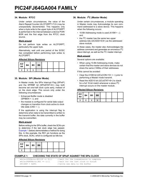
<strong>PIC24FJ64GA004</strong> FAMILY34. Module: RTCCUnder certain circumstances, the value of theAlarm Repeat Counter (ALCFGRPT) may beunexpectedly decremented. This happens onlywhen a byte write to the upper byte of ALCFGRPTis performed in the interval between a device POR/BOR <strong>and</strong> the first edge from the RTCC clocksource.Work aroundDo not perform byte writes on ALCFGRPT,particularly the upper byte.Alternatively, wait until one period of the SOSChas completed before performing byte writes toALCFGRPT.Affected <strong>Silicon</strong> RevisionsA3/A4B4 B5 B8X X X35. Module: SPI (Master Mode)In Master mode, the SPIx Interrupt Flag (SPIxIF)<strong>and</strong> the SPIRBF bit (SPIxSTAT) may bothbecome set one-half clock cycle early, instead ofon the clock edge. This occurs only under thefollowing circumstances:• Enhanced Buffer mode is disabled(SPIBEN = 0); <strong>and</strong>• the module is configured for serial data outputchanges on transition from clock active to clockIdle state (CKE = 1).If the application is using the interrupt flag todetermine when data to be transmitted is written tothe transmit buffer, the data currently in the buffermay be overwritten.Work aroundBefore writing to the SPIx buffer, check the SCKx pinto determine if the last clock edge has passed.Example 1 (below) demonstrates a method for doingthis. In this example, the RD1 pin functions as theSPIx clock, SCKx, which is configured as Idle low.Affected <strong>Silicon</strong> Revisions36. Module: I 2 C (Master Mode)Under certain circumstances, a module operatingin Master mode may Acknowledge its own comm<strong>and</strong>addressed to a slave device. This happenswhen the following occurs:• 10-Bit Addressing mode is used (A10M = 1);<strong>and</strong>• the I 2 C master has the same two upperaddress bits (I2CADD) as the addressedslave module.In these cases, the master also Acknowledges theaddress comm<strong>and</strong> <strong>and</strong> generates an erroneous I 2 Cslave interrupt, as well as the I 2 C master interrupt.Work aroundSeveral options are available:• When using 10-Bit Addressing mode, makecertain that the master <strong>and</strong> slave devices do notshare the same 2 MSbs of their addresses.If this cannot be avoided:• Clear the A10M bit (I2CxCON = 0) prior toperforming a Master mode transmit.• Read the ADD10 bit (I2CxSTAT) to checkfor a full 10-bit match whenever a slave I 2 Cinterrupt occurs on the master module.Affected <strong>Silicon</strong> RevisionsA3/A4B4 B5 B8X X X XA3/A4XB4 B5 B8EXAMPLE 1: CHECKING THE STATE OF SPIxIF AGAINST THE SPIx CLOCKwhile(IFS0bits.SPI1IF == 0){} //wait for the transmission to completewhile(PORTDbits.RD1 == 1){} //wait for the last clock to finishSPI1BUF = 0xFF;//write new data to the bufferDS80470G-page 14 2009-2013 <strong>Microchip</strong> Technology Inc.