PIC24FJ64GA004 Family Silicon Errata and Data Sheet ... - Microchip
PIC24FJ64GA004 Family Silicon Errata and Data Sheet ... - Microchip
PIC24FJ64GA004 Family Silicon Errata and Data Sheet ... - Microchip

Create successful ePaper yourself
Turn your PDF publications into a flip-book with our unique Google optimized e-Paper software.
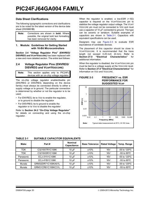
<strong>PIC24FJ64GA004</strong> FAMILY<strong>Data</strong> <strong>Sheet</strong> ClarificationsThe following typographic corrections <strong>and</strong> clarificationsare to be noted for the latest version of the device datasheet (DS39881D):Note:1. Module: Guidelines for Getting Startedwith 16-Bit MicrocontrollersSection 2.4 “Voltage Regulator Pins” (ENVREG/DISVREG <strong>and</strong> VCAP/VDDCORE) has been replaced witha new <strong>and</strong> more detailed section. The entire text follows:2.4 Voltage Regulator Pins (ENVREG/DISVREG <strong>and</strong> VCAP/VDDCORE)Note:Corrections are shown in bold. Wherepossible, the original bold text formattinghas been removed for clarity.This section applies only to PIC24FJdevices with an on-chip voltage regulator.The on-chip voltage regulator enable/disable pin(ENVREG or DISVREG, depending on the devicefamily) must always be connected directly to either asupply voltage or to ground. The particular connectionis determined by whether or not the regulator is to beused:• For ENVREG, tie to VDD to enable the regulator,or to ground to disable the regulator• For DISVREG, tie to ground to enable theregulator or to VDD to disable the regulatorRefer to Section 24.2 “On-Chip Voltage Regulator”for details on connecting <strong>and</strong> using the on-chipregulator.When the regulator is enabled, a low-ESR (< 5Ω)capacitor is required on the VCAP/VDDCORE pin tostabilize the voltage regulator output voltage. The VCAP/VDDCORE pin must not be connected to VDD <strong>and</strong> mustuse a capacitor of 10 µF connected to ground. The typecan be ceramic or tantalum. Suitable examples ofcapacitors are shown in Table 2-1. Capacitors withequivalent specifications can be used.Designers may use Figure 2-3 to evaluate ESRequivalence of c<strong>and</strong>idate devices.The placement of this capacitor should be close toVCAP/VDDCORE. It is recommended that the tracelength not exceed 0.25 inch (6 mm). Refer toSection 27.0 “Electrical Characteristics” foradditional information.When the regulator is disabled, the VCAP/VDDCORE pinmust be tied to a voltage supply at the VDDCORE level.Refer to Section 27.0 “Electrical Characteristics” forinformation on VDD <strong>and</strong> VDDCORE.FIGURE 2-3ESR ()1010.10.01FREQUENCY vs. ESRPERFORMANCE FORSUGGESTED VCAP0.0010.01 0.1 1 10 100 1000 10,000Frequency (MHz)Note:Typical data measurement at 25°C, 0V DC bias..TABLE 2-1SUITABLE CAPACITOR EQUIVALENTSMake Part #NominalCapacitanceBase Tolerance Rated Voltage Temp. RangeTDK C3216X7R1C106K 10 µF ±10% 16V -55 to 125ºCTDK C3216X5R1C106K 10 µF ±10% 16V -55 to 85ºCPanasonic ECJ-3YX1C106K 10 µF ±10% 16V -55 to 125ºCPanasonic ECJ-4YB1C106K 10 µF ±10% 16V -55 to 85ºCMurata GRM32DR71C106KA01L 10 µF ±10% 16V -55 to 125ºCMurata GRM31CR61C106KC31L 10 µF ±10% 16V -55 to 85ºCDS80470G-page 20 2009-2013 <strong>Microchip</strong> Technology Inc.