PIC24FJ64GA004 Family Silicon Errata and Data Sheet ... - Microchip
PIC24FJ64GA004 Family Silicon Errata and Data Sheet ... - Microchip
PIC24FJ64GA004 Family Silicon Errata and Data Sheet ... - Microchip

Create successful ePaper yourself
Turn your PDF publications into a flip-book with our unique Google optimized e-Paper software.
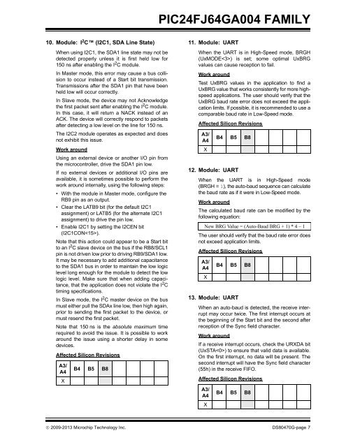
<strong>PIC24FJ64GA004</strong> FAMILY10. Module: I 2 C (I2C1, SDA Line State)When using I2C1, the SDA1 line state may not bedetected properly unless it is first held low for150 ns after enabling the I 2 C module.In Master mode, this error may cause a bus collisionto occur instead of a Start bit transmission.Transmissions after the SDA1 pin that have beenheld low will occur correctly.In Slave mode, the device may not Acknowledgethe first packet sent after enabling the I 2 C module.In this case, it will return a NACK instead of anACK. The device will correctly respond to packetsafter detecting a low level on the line for 150 ns.The I2C2 module operates as expected <strong>and</strong> doesnot exhibit this issue.Work aroundUsing an external device or another I/O pin fromthe microcontroller, drive the SDA1 pin low.If no external devices or additional I/O pins areavailable, it is sometimes possible to perform thework around internally, using the following steps:• With the module in Master mode, configure theRB9 pin as an output.• Clear the LATB9 bit (for the default I2C1assignment) or LATB5 (for the alternate I2C1assignment) to drive the pin low.• Enable I2C1 by setting the I2CEN bit(I2C1CON).Note that this action could appear to be a Start bitto an I 2 C slave device on the bus if the RB8/SCL1pin is not driven low prior to driving RB9/SDA1 low.It may be necessary to add additional capacitanceto the SDA1 bus in order to maintain the low logiclevel long enough for the module to detect the lowlogic level. Make sure that when adding capacitance,that the application does not violate the I 2 Ctiming specifications.In Slave mode, the I 2 C master device on the busmust either pull the SDAx line low, then high again,prior to sending the first packet to the device, ormust resend the first packet.Note that 150 ns is the absolute maximum timerequired to avoid the issue. It is possible to workaround the issue using a shorter delay in somedevices.Affected <strong>Silicon</strong> RevisionsA3/A4XB4 B5 B811. Module: UARTWhen the UART is in High-Speed mode, BRGH(UxMODE) is set; some optimal UxBRGvalues can cause reception to fail.Work aroundTest UxBRG values in the application to find aUxBRG value that works consistently for more highspeedapplications. The user should verify that theUxBRG baud rate error does not exceed the applicationlimits. If possible, it is recommended to use acomparable baud rate in Low-Speed mode.Affected <strong>Silicon</strong> RevisionsA3/A4X12. Module: UARTWhen the UART is in High-Speed mode(BRGH = 1), the auto-baud sequence can calculatethe baud rate as if it were in Low-Speed mode.Work aroundThe calculated baud rate can be modified by thefollowing equation:New BRG Value = (Auto-Baud BRG + 1) * 4 – 1The user should verify that the baud rate error doesnot exceed application limits.Affected <strong>Silicon</strong> RevisionsA3/A4XB4 B5 B8B4 B5 B813. Module: UARTWhen an auto-baud is detected, the receive interruptmay occur twice. The first interrupt occurs atthe beginning of the Start bit <strong>and</strong> the second afterreception of the Sync field character.Work aroundIf a receive interrupt occurs, check the URXDA bit(UxSTA) to ensure that valid data is available.On the first interrupt, no data will be present. Thesecond interrupt will have the Sync field character(55h) in the receive FIFO.Affected <strong>Silicon</strong> RevisionsA3/A4XB4 B5 B8 2009-2013 <strong>Microchip</strong> Technology Inc. DS80470G-page 7