dsPIC33FJ12MC201/202 Data Sheet - Microchip
dsPIC33FJ12MC201/202 Data Sheet - Microchip
dsPIC33FJ12MC201/202 Data Sheet - Microchip

Create successful ePaper yourself
Turn your PDF publications into a flip-book with our unique Google optimized e-Paper software.
<strong>dsPIC33FJ12MC201</strong>/<strong>202</strong><strong>Data</strong> <strong>Sheet</strong>High-Performance,16-bit Digital Signal Controllers© 2007-2011 <strong>Microchip</strong> Technology Inc. DS70265E
Note the following details of the code protection feature on <strong>Microchip</strong> devices:• <strong>Microchip</strong> products meet the specification contained in their particular <strong>Microchip</strong> <strong>Data</strong> <strong>Sheet</strong>.• <strong>Microchip</strong> believes that its family of products is one of the most secure families of its kind on the market today, when used in theintended manner and under normal conditions.• There are dishonest and possibly illegal methods used to breach the code protection feature. All of these methods, to ourknowledge, require using the <strong>Microchip</strong> products in a manner outside the operating specifications contained in <strong>Microchip</strong>’s <strong>Data</strong><strong>Sheet</strong>s. Most likely, the person doing so is engaged in theft of intellectual property.• <strong>Microchip</strong> is willing to work with the customer who is concerned about the integrity of their code.• Neither <strong>Microchip</strong> nor any other semiconductor manufacturer can guarantee the security of their code. Code protection does notmean that we are guaranteeing the product as “unbreakable.”Code protection is constantly evolving. We at <strong>Microchip</strong> are committed to continuously improving the code protection features of ourproducts. Attempts to break <strong>Microchip</strong>’s code protection feature may be a violation of the Digital Millennium Copyright Act. If such actsallow unauthorized access to your software or other copyrighted work, you may have a right to sue for relief under that Act.Information contained in this publication regarding deviceapplications and the like is provided only for your convenienceand may be superseded by updates. It is your responsibility toensure that your application meets with your specifications.MICROCHIP MAKES NO REPRESENTATIONS ORWARRANTIES OF ANY KIND WHETHER EXPRESS ORIMPLIED, WRITTEN OR ORAL, STATUTORY OROTHERWISE, RELATED TO THE INFORMATION,INCLUDING BUT NOT LIMITED TO ITS CONDITION,QUALITY, PERFORMANCE, MERCHANTABILITY ORFITNESS FOR PURPOSE. <strong>Microchip</strong> disclaims all liabilityarising from this information and its use. Use of <strong>Microchip</strong>devices in life support and/or safety applications is entirely atthe buyer’s risk, and the buyer agrees to defend, indemnify andhold harmless <strong>Microchip</strong> from any and all damages, claims,suits, or expenses resulting from such use. No licenses areconveyed, implicitly or otherwise, under any <strong>Microchip</strong>intellectual property rights.TrademarksThe <strong>Microchip</strong> name and logo, the <strong>Microchip</strong> logo, dsPIC,KEELOQ, KEELOQ logo, MPLAB, PIC, PICmicro, PICSTART,PIC 32 logo, rfPIC and UNI/O are registered trademarks of<strong>Microchip</strong> Technology Incorporated in the U.S.A. and othercountries.FilterLab, Hampshire, HI-TECH C, Linear Active Thermistor,MXDEV, MXLAB, SEEVAL and The Embedded ControlSolutions Company are registered trademarks of <strong>Microchip</strong>Technology Incorporated in the U.S.A.Analog-for-the-Digital Age, Application Maestro, chipKIT,chipKIT logo, CodeGuard, dsPICDEM, dsPICDEM.net,dsPICworks, dsSPEAK, ECAN, ECONOMONITOR,FanSense, HI-TIDE, In-Circuit Serial Programming, ICSP,Mindi, MiWi, MPASM, MPLAB Certified logo, MPLIB,MPLINK, mTouch, Omniscient Code Generation, PICC,PICC-18, PICDEM, PICDEM.net, PICkit, PICtail, REAL ICE,rfLAB, Select Mode, Total Endurance, TSHARC,UniWinDriver, WiperLock and ZENA are trademarks of<strong>Microchip</strong> Technology Incorporated in the U.S.A. and othercountries.SQTP is a service mark of <strong>Microchip</strong> Technology Incorporatedin the U.S.A.All other trademarks mentioned herein are property of theirrespective companies.© 2007-2011, <strong>Microchip</strong> Technology Incorporated, Printed inthe U.S.A., All Rights Reserved.Printed on recycled paper.ISBN: 978-1-61341-368-5<strong>Microchip</strong> received ISO/TS-16949:2009 certification for its worldwideheadquarters, design and wafer fabrication facilities in Chandler andTempe, Arizona; Gresham, Oregon and design centers in Californiaand India. The Company’s quality system processes and proceduresare for its PIC ® MCUs and dsPIC ® DSCs, KEELOQ ® code hoppingdevices, Serial EEPROMs, microperipherals, nonvolatile memory andanalog products. In addition, <strong>Microchip</strong>’s quality system for the designand manufacture of development systems is ISO 9001:2000 certified.DS70265E-page 2© 2007-2011 <strong>Microchip</strong> Technology Inc.
<strong>dsPIC33FJ12MC201</strong>/<strong>202</strong>High-Performance, 16-bit Digital Signal ControllersOperating Range:• Up to 40 MIPS operation (at 3.0-3.6V):- Industrial temperature range (-40°C to +85°C)- Extended temperature range (-40°C to +125°C)High-Performance DSC CPU:• Modified Harvard architecture• C compiler optimized instruction set• 16-bit-wide data path• 24-bit-wide instructions• Linear program memory addressing up to 4Minstruction words• Linear data memory addressing up to 64 Kbytes• 83 base instructions: mostly one word/one cycle• Two 40-bit accumulators with rounding andsaturation options• Flexible and powerful addressing modes:- Indirect- Modulo- Bit-Reversed• Software stack• 16 x 16 fractional/integer multiply operations• 32/16 and 16/16 divide operations• Single-cycle multiply and accumulate:- Accumulator write back for DSP operations- Dual data fetch• Up to ±16-bit shifts for up to 40-bit dataTimers/Capture/Compare/PWM:• Timer/Counters, up to three 16-bit timers- Can pair up to make one 32-bit timer- One timer runs as Real-Time Clock withexternal 32.768 kHz oscillator- Programmable prescaler• Input Capture (up to four channels):- Capture on up, down, or both edges- 16-bit capture input functions- 4-deep FIFO on each capture• Output Compare (up to two channels):- Single or Dual 16-bit Compare mode- 16-bit Glitchless PWM modeInterrupt Controller:• 5-cycle latency• Up to 26 available interrupt sources• Up to three external interrupts• Seven programmable priority levels• Four processor exceptionsDigital I/O:• Peripheral pin Select functionality• Up to 21 programmable digital I/O pins• Wake-up/Interrupt-on-Change for up to 21 pins• Output pins can drive from 3.0V to 3.6V• Up to 5V output with open drain configurations on5V tolerant pins• 4 mA sink on all I/O pinsOn-Chip Flash and SRAM:• Flash program memory (12 Kbytes)• <strong>Data</strong> SRAM (1024 bytes)• Boot and General Security for program FlashSystem Management:• Flexible clock options:- External, crystal, resonator, internal RC- Fully integrated Phase-Locked Loop (PLL)- Extremely low-jitter PLL• Power-up Timer• Oscillator Start-up Timer/Stabilizer• Watchdog Timer with its own RC oscillator• Fail-Safe Clock Monitor• Reset by multiple sourcesPower Management:• On-chip 2.5V voltage regulator• Switch between clock sources in real time• Idle, Sleep, and Doze modes with fast wake-up© 2007-2011 <strong>Microchip</strong> Technology Inc. DS70265E-page 3
<strong>dsPIC33FJ12MC201</strong>/<strong>202</strong>Motor Control Peripherals:• 6-channel 16-bit Motor Control PWM:- Three duty cycle generators- Independent or Complementary mode- Programmable dead time and output polarity- Edge-aligned or center-aligned- Manual output override control- One Fault input- Trigger for ADC conversions- PWM frequency for 16-bit resolution(@ 40 MIPS) = 1220 Hz for Edge-Alignedmode, 610 Hz for Center-Aligned mode- PWM frequency for 11-bit resolution(@ 40 MIPS) = 39.1 kHz for Edge-Alignedmode, 19.55 kHz for Center-Aligned mode• 2-channel 16-bit Motor Control PWM:- One duty cycle generator- Independent or Complementary mode- Programmable dead time and output polarity- Edge-aligned or center-aligned- Manual output override control- One Fault input- Trigger for ADC conversions- PWM frequency for 16-bit resolution(@ 40 MIPS) = 1220 Hz for Edge-Alignedmode, 610 Hz for Center-Aligned mode- PWM frequency for 11-bit resolution(@ 40 MIPS) = 39.1 kHz for Edge-Alignedmode, 19.55 kHz for Center-Aligned mode• Quadrature Encoder Interface module:- Phase A, Phase B, and index pulse input- 16-bit up/down position counter- Count direction status- Position Measurement (x2 and x4) mode- Programmable digital noise filters on inputs- Alternate 16-bit Timer/Counter mode- Interrupt on position counter rollover/underflowCMOS Flash Technology:• Low-power, high-speed Flash technology• Fully static design• 3.3V (±10%) operating voltage• Industrial and Extended temperature• Low power consumptionCommunication Modules:• 4-wire SPI:- Framing supports I/O interface to simplecodecs- Supports 8-bit and 16-bit data- Supports all serial clock formats andsampling modes• I 2 C:- Full Multi-Master Slave mode support- 7-bit and 10-bit addressing- Bus collision detection and arbitration- Integrated signal conditioning- Slave address masking• UART:- Interrupt on address bit detect- Interrupt on UART error- Wake-up on Start bit from Sleep mode- 4-character TX and RX FIFO buffers- LIN bus support- IrDA ® encoding and decoding in hardware- High-Speed Baud mode- Hardware Flow Control with CTS and RTSPackaging:• 20-pin PDIP/SOIC/SSOP• 28-pin SPDIP/SOIC/SSOP/QFNNote:See Table 1 for the exact peripheralfeatures per device.Analog-to-Digital Converters (ADCs):• 10-bit, 1.1 Msps or 12-bit, 500 Ksps conversion:- Two and four simultaneous samples (10-bit ADC)- Up to six input channels with auto-scanning- Conversion start can be manual orsynchronized with one of four trigger sources- Conversion possible in Sleep mode- ±2 LSb max integral nonlinearity- ±1 LSb max differential nonlinearityDS70265E-page 4© 2007-2011 <strong>Microchip</strong> Technology Inc.
<strong>dsPIC33FJ12MC201</strong>/<strong>202</strong><strong>dsPIC33FJ12MC201</strong>/<strong>202</strong> PRODUCTFAMILIESThe device names, pin counts, memory sizes, andperipheral availability of each device are listed inTable 1. The following pages show their pinoutdiagrams.TABLE 1:<strong>dsPIC33FJ12MC201</strong>/<strong>202</strong> CONTROLLER FAMILIESDevicePinsProgram Flash Memory(Kbyte)RAM (Kbyte)Remappable Pins16-bit TimerInput CaptureRemappable PeripheralsOutput CompareStandard PWMMotor Control PWMQuadrature EncoderInterfaceUARTExternal Interrupts (3)SPI10-Bit/12-Bit ADCI 2 CI/O PinsPackages<strong>dsPIC33FJ12MC201</strong> 20 12 1 10 3 (1) 4 2 4ch (2)dsPIC33FJ12MC<strong>202</strong> 28 12 1 16 3 (1) 4 2 6ch (2)Note 1: Only two out of three timers are remappable.2: Only PWM fault inputs are remappable.3: Only two out of three interrupts are remappable.2ch (2) 4 ch1 1 3 1 1ADC,2ch (2) 6 ch1 1 3 1 1ADC.1 15 PDIPSOICSSOP1 21 SPDIPSOICSSOPQFN© 2007-2011 <strong>Microchip</strong> Technology Inc. DS70265E-page 5
<strong>dsPIC33FJ12MC201</strong>/<strong>202</strong>Pin Diagrams20-PIN PDIP, SOIC, SSOP= Pins are up to 5V tolerantMCLRPGED2/AN0/VREF+/CN2/RA0PGEC2/AN1/VREF-/CN3/RA1PGED1/AN2/RP0 (1) /CN4/RB0PGEC1/AN3/RP1 (1) /CN5/RB1VSSOSC1/CLKI/CN30/RA2OSC2/CLKO/CN29/RA3PGED3/SOSCI/RP4 (1) /CN1/RB4PGEC3/SOSCO/T1CK/CN0/RA412345678910<strong>dsPIC33FJ12MC201</strong>20191817161514131211VDDVSSPWM1L1/RP15 (1) /CN11/RB15PWM1H1/RP14 (1) /CN12/RB14PWM1L2/RP13 (1) /CN13/RB13PWM1H2/RP12 (1) /CN14/RB12VCAPPWM2L1/SDA1/RP9 (1) /CN21/RB9PWM2H1/SCL1/RP8 (1) /CN22/RB8INT0/RP7 (1) /CN23/RB728-PIN SPDIP, SOIC, SSOP= Pins are up to 5V tolerantMCLRPGED2/AN0/VREF+/CN2/RA0PGEC2/AN1/VREF-/CN3/RA1PGED1/AN2/RP0 (1) /CN4/RB0PGEC1/AN3/RP1 (1) /CN5/RB1AN4/RP2 (1) /CN6/RB2AN5/RP3 (1) /CN7/RB3VSSOSC1/CLKI/CN30/RA2OSC2/CLKO/CN29/RA3PGED3/SOSCI/RP4 (1) /CN1/RB4PGEC3/SOSCO/T1CK/CN0/RA4VDDASDA1/RP5 (1) /CN27/RB51234567891011121314dsPIC33FJ12MC<strong>202</strong>2827262524232221201918171615AVDDAVSSPWM1L1/RP15 (1) /CN11/RB15PWM1H1/RP14 (1) /CN12/RB14PWM1L2/RP13 (1) /CN13/RB13PWM1H2/RP12 (1) /CN14/RB12TMS/PWM1L3/RP11 (1) /CN15/RB11TDI/PWM1H3/RP10 (1) /CN16/RB10VCAPVSSTDO/PWM2L1/SDA1/RP9 (1) /CN21/RB9TCK/PWM2H1/SCL1/RP8 (1) /CN22/RB8INT0/RP7 (1) /CN23/RB7ASCL1/RP6 (1) /CN24/RB6Note 1:The RPn pins can be used by any remappable peripheral. See Table 1 for the list of availableperipherals.DS70265E-page 6© 2007-2011 <strong>Microchip</strong> Technology Inc.
<strong>dsPIC33FJ12MC201</strong>/<strong>202</strong>Pin Diagrams (Continued)28-Pin QFN (2) 1= Pins are up to 5V tolerantPGED1/AN2/RP0 (1) /CN4/RB021PWM1L2/RP13 (1) /CN13/RB13PGEC1/AN3/RP1 (1) /CN5/RB1220PWM1H2/RP12 (1) /CN14/RB12AN4/RP2 (1) /CN6/RB2319TMS/PWM1L3/RP11 (1) /CN15/RB11AN5/RP3 (1) /CN7/RB34dsPIC33FJ12MC<strong>202</strong>18TDI/PWM1H3/RP10 (1) /CN16/RB10517VCAPOSC1/CLKI/CN30/RA2616VSSOSC2/CLKO/CN29/RA37158 9 10 11 12 13 14TDO/PWM2L1/SDA1/RP9 (1) /CN21/RB9PGED3/SOSCI/RP4 (1) /CN1/RB4PGEC3/SOSCO/T1CK/CN0/RA4VDDASDA1/RP5 (1) /CN27/RB5ASCL1/RP6 (1) /CN24/RB6INT0/RP7 (1) /CN23/RB7TCK/PWM2H1/SCL1/RP8 (1) /CN22/RB8PGEC2/AN1/VREF-/CN3/RA1PGED2/AN0/VREF+/CN2/RA0MCLRAVDDAVSSPWM1L1/RP15 (1) /CN11/RB15PWM1H1/ RP14 (1) /CN12/RB1428 27 26 25 24 23 22VSSNote 1: The RPn pins can be used by any remappable peripheral. See Table 1 for the list of availableperipherals.2: The metal plane at the bottom of the device is not connected to any pins and is recommended tobe connected to VSS externally.© 2007-2011 <strong>Microchip</strong> Technology Inc. DS70265E-page 7
<strong>dsPIC33FJ12MC201</strong>/<strong>202</strong>Table of Contents<strong>dsPIC33FJ12MC201</strong>/<strong>202</strong> Product Families ........................................................................................................................................... 51.0 Device Overview .......................................................................................................................................................................... 92.0 Guidelines for Getting Started with 16-bit Digital Signal Controllers .......................................................................................... 153.0 CPU............................................................................................................................................................................................ 194.0 Memory Organization ................................................................................................................................................................. 315.0 Flash Program Memory.............................................................................................................................................................. 576.0 Resets ....................................................................................................................................................................................... 637.0 Interrupt Controller ..................................................................................................................................................................... 718.0 Oscillator Configuration ............................................................................................................................................................ 1039.0 Power-Saving Features............................................................................................................................................................ 11310.0 I/O Ports ................................................................................................................................................................................... 11911.0 Timer1 ...................................................................................................................................................................................... 14112.0 Timer2/3 Feature ..................................................................................................................................................................... 14313.0 Input Capture............................................................................................................................................................................ 14914.0 Output Compare....................................................................................................................................................................... 15115.0 Motor Control PWM Module ..................................................................................................................................................... 15516.0 Quadrature Encoder Interface (QEI) Module ........................................................................................................................... 16917.0 Serial Peripheral Interface (SPI)............................................................................................................................................... 17318.0 Inter-Integrated Circuit (I 2 C).............................................................................................................................................. 17919.0 Universal Asynchronous Receiver Transmitter (UART) ........................................................................................................... 18720.0 10-bit/12-bit Analog-to-Digital Converter (ADC) ....................................................................................................................... 19321.0 Special Features ...................................................................................................................................................................... 20522.0 Instruction Set Summary .......................................................................................................................................................... 21123.0 Development Support............................................................................................................................................................... 21924.0 Electrical Characteristics .......................................................................................................................................................... 22325.0 Packaging Information.............................................................................................................................................................. 271Appendix A: Revision History............................................................................................................................................................. 287Index ................................................................................................................................................................................................. 297The <strong>Microchip</strong> Web Site ..................................................................................................................................................................... 301Customer Change Notification Service .............................................................................................................................................. 301Customer Support .............................................................................................................................................................................. 301Reader Response .............................................................................................................................................................................. 302Product Identification System............................................................................................................................................................. 303TO OUR VALUED CUSTOMERSIt is our intention to provide our valued customers with the best documentation possible to ensure successful use of your <strong>Microchip</strong>products. To this end, we will continue to improve our publications to better suit your needs. Our publications will be refined andenhanced as new volumes and updates are introduced.If you have any questions or comments regarding this publication, please contact the Marketing Communications Departmentvia E-mail at docerrors@microchip.com or fax the Reader Response Form in the back of this data sheet to (480) 792-4150.We welcome your feedback.Most Current <strong>Data</strong> <strong>Sheet</strong>To obtain the most up-to-date version of this data sheet, please register at our Worldwide Web site at:http://www.microchip.comYou can determine the version of a data sheet by examining its literature number found on the bottom outside corner of any page.The last character of the literature number is the version number, (e.g., DS30000A is version A of document DS30000).ErrataAn errata sheet, describing minor operational differences from the data sheet and recommended workarounds, may exist for currentdevices. As device/documentation issues become known to us, we will publish an errata sheet. The errata will specify the revisionof silicon and revision of document to which it applies.To determine if an errata sheet exists for a particular device, please check with one of the following:• <strong>Microchip</strong>’s Worldwide Web site; http://www.microchip.com• Your local <strong>Microchip</strong> sales office (see last page)When contacting a sales office, please specify which device, revision of silicon and data sheet (include literature number) you areusing.Customer Notification SystemRegister on our web site at www.microchip.com to receive the most current information on all of our products.DS70265E-page 8© 2007-2011 <strong>Microchip</strong> Technology Inc.
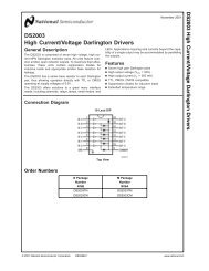
<strong>dsPIC33FJ12MC201</strong>/<strong>202</strong>1.0 DEVICE OVERVIEWNote 1: This data sheet summarizes the featuresof the <strong>dsPIC33FJ12MC201</strong>/<strong>202</strong> devices.It is not intended to be a comprehensivereference source. To complement theinformation in this data sheet, refer to the“dsPIC33F/PIC24H Family ReferenceManual”. Please see the <strong>Microchip</strong> website (www.microchip.com) for the latestdsPIC33F/PIC24H Family ReferenceManual sections.2: Some registers and associated bitsdescribed in this section may not beavailable on all devices. Refer toSection 4.0 “Memory Organization” inthis data sheet for device-specific registerand bit information.This document contains device specific information forthe <strong>dsPIC33FJ12MC201</strong>/<strong>202</strong> Digital Signal Controller(DSC) Devices. The dsPIC33F devices containextensive Digital Signal Processor (DSP) functionalitywith a high-performance, 16-bit microcontroller (MCU)architecture.Figure 1-1 shows a general block diagram of the coreand peripheral modules in the <strong>dsPIC33FJ12MC201</strong>/<strong>202</strong> family of devices. Table 1-1 lists the functions ofthe various pins shown in the pinout diagrams.© 2007-2011 <strong>Microchip</strong> Technology Inc. DS70265E-page 9
<strong>dsPIC33FJ12MC201</strong>/<strong>202</strong>FIGURE 1-1:PSV and Table<strong>Data</strong> AccessControl Block<strong>dsPIC33FJ12MC201</strong>/<strong>202</strong> BLOCK DIAGRAMY <strong>Data</strong> BusInterruptControllerX <strong>Data</strong> BusPORTA8161616162323Address Latch23PCU PCH PCLProgram CounterStack LoopControl ControlLogic Logic<strong>Data</strong> LatchX RAMAddressLatch16<strong>Data</strong> LatchY RAMAddressLatch16Address Generator Units16PORTBRemappablePinsProgram MemoryEA MUX<strong>Data</strong> Latch24ROM Latch16 16InstructionDecode andControlInstruction RegLiteral <strong>Data</strong>16Control Signalsto Various BlocksDSP EngineOSC2/CLKOOSC1/CLKITimingGenerationFRC/LPRCOscillatorsPrecisionBand GapReferenceVoltageRegulatorPower-upTimerOscillatorStart-up TimerPower-onResetWatchdogTimerBrown-outResetDivide Support16 x 16W Register Array16-bit ALU1616VCAPVDD, VSSMCLRTimers1-3UART1ADC1OC/PWM1-2PWM2 ChSPI1IC1,2,7,8CNxI2C1QEIPWM6 ChNote:Not all pins or features are implemented on all device pinout configurations. See “Pin Diagrams” for the specific pins and featurespresent on each device.DS70265E-page 10© 2007-2011 <strong>Microchip</strong> Technology Inc.
<strong>dsPIC33FJ12MC201</strong>/<strong>202</strong>TABLE 1-1:Pin NamePinTypePINOUT I/O DESCRIPTIONSBufferTypePPSAN0-AN5 I Analog No Analog input channels.CLKICLKOOSC1OSC2SOSCISOSCOCN0-CN7CN11-CN16CN21-CN24CN27CN29-CN30IC1-IC2IC7-IC8OCFAOC1-OC2INT0INT1INT2IOII/OIOST/CMOS—ST/CMOS—ST/CMOS—NoNoNoNoNoNoI ST NoNoNoNoNoIIIOIIISTSTST—STSTSTYesYesYesYesNoYesYesDescriptionExternal clock source input. Always associated with OSC1 pin function.Oscillator crystal output. Connects to crystal or resonator in Crystal Oscillatormode. Optionally functions as CLKO in RC and EC modes. Always associatedwith OSC2 pin function.Oscillator crystal input. ST buffer when configured in RC mode; CMOSotherwise.Oscillator crystal output. Connects to crystal or resonator in Crystal Oscillatormode. Optionally functions as CLKO in RC and EC modes.32.768 kHz low-power oscillator crystal input; CMOS otherwise.32.768 kHz low-power oscillator crystal output.Change notification inputs.Can be software programmed for internal weak pull-ups on all inputs.Capture inputs 1/2.Capture inputs 7/8.Compare Fault A input (for Compare Channels 1 and 2).Compare outputs 1 through 2.External interrupt 0.External interrupt 1.External interrupt 2.RA0-RA4 I/O ST No PORTA is a bidirectional I/O port.RB0-RB15 I/O ST No PORTB is a bidirectional I/O port.T1CKT2CKT3CKU1CTSU1RTSU1RXU1TXSCK1SDI1SDO1SS1SCL1SDA1ASCL1ASDA1TMSTCKTDITDOIIIIOIOI/OIOI/OI/OI/OI/OI/OIIIOSTSTSTST—ST—STST—STSTSTSTSTSTSTST—NoYesYesYesYesYesYesYesYesYesYesNoNoNoNoNoNoNoNoTimer1 external clock input.Timer2 external clock input.Timer3 external clock input.UART1 clear to send.UART1 ready to send.UART1 receive.UART1 transmit.Synchronous serial clock input/output for SPI1.SPI1 data in.SPI1 data out.SPI1 slave synchronization or frame pulse I/O.Synchronous serial clock input/output for I2C1.Synchronous serial data input/output for I2C1.Alternate synchronous serial clock input/output for I2C1.Alternate synchronous serial data input/output for I2C1.JTAG Test mode select pin.JTAG test clock input pin.JTAG test data input pin.JTAG test data output pin.Legend: CMOS = CMOS compatible input or output Analog = Analog input P = PowerST = Schmitt Trigger input with CMOS levels O = Output I = InputPPS = Peripheral Pin Select© 2007-2011 <strong>Microchip</strong> Technology Inc. DS70265E-page 11
<strong>dsPIC33FJ12MC201</strong>/<strong>202</strong>TABLE 1-1:Pin NamePinTypePINOUT I/O DESCRIPTIONS (CONTINUED)BufferTypePPSDescriptionINDXQEAQEBUPDNIIIOSTSTSTCMOSYesYesYesYesQuadrature Encoder Index Pulse input.Quadrature Encoder Phase A input in QEI mode.Auxiliary Timer External Clock/Gate input in Timer mode.Quadrature Encoder Phase A input in QEI mode.Auxiliary Timer External Clock/Gate input in Timer mode.Position Up/Down Counter Direction State.FLTA1PWM1L1PWM1H1PWM1L2PWM1H2PWM1L3PWM1H3IOOOOOOST——————YesNoNoNoNoNoNoPWM1 Fault A input.PWM1 Low output 1PWM1 High output 1PWM1 Low output 2PWM1 High output 2PWM1 Low output 3PWM1 High output 3FLTA2 I ST Yes PWM2 Fault A input.PWM2L1 O — No PWM2 Low output 1PWM2H1 O — No PWM2 High output 1PGED1PGEC1PGED2PGEC2PGED3PGEC3I/OII/OII/OISTSTSTSTSTSTNoNoNoNoNoNo<strong>Data</strong> I/O pin for programming/debugging communication channel 1.Clock input pin for programming/debugging communication channel 1.<strong>Data</strong> I/O pin for programming/debugging communication channel 2.Clock input pin for programming/debugging communication channel 2.<strong>Data</strong> I/O pin for programming/debugging communication channel 3.Clock input pin for programming/debugging communication channel 3.MCLR I/P ST No Master Clear (Reset) input. This pin is an active-low Reset to the device.AVDD P P No Positive supply for analog modules. This pin must be connected at all times.AVSS P P No Ground reference for analog modules.VDD P — No Positive supply for peripheral logic and I/O pins.VCAP P — No CPU logic filter capacitor connection.VSS P — No Ground reference for logic and I/O pins.VREF+ I Analog No Analog voltage reference (high) input.VREF- I Analog No Analog voltage reference (low) input.Legend: CMOS = CMOS compatible input or output Analog = Analog input P = PowerST = Schmitt Trigger input with CMOS levels O = Output I = InputPPS = Peripheral Pin SelectDS70265E-page 12© 2007-2011 <strong>Microchip</strong> Technology Inc.
<strong>dsPIC33FJ12MC201</strong>/<strong>202</strong>1.1 Referenced SourcesThis device data sheet is based on the followingindividual chapters of the “dsPIC33F/PIC24H FamilyReference Manual”. These documents should beconsidered as the general reference for the operationof a particular module or device feature.Note 1:To access the documents listed below,browse to the documentation section ofthe dsPIC33FJ12MC<strong>202</strong> product page ofthe <strong>Microchip</strong> web site(www.microchip.com) or select a familyreference manual section from thefollowing list.In addition to parameters, features, andother documentation, the resulting pageprovides links to the related familyreference manual sections.• Section 1. “Introduction” (DS70197)• Section 2. “CPU” (DS70204)• Section 3. “<strong>Data</strong> Memory” (DS70<strong>202</strong>)• Section 4. “Program Memory” (DS70<strong>202</strong>)• Section 5. “Flash Programming” (DS70191)• Section 6. “Interrupts” (DS70184)• Section 7. “Oscillator” (DS70186)• Section 8. “Reset” (DS70192)• Section 9. “Watchdog Timer and Power-Saving Modes” (DS70196)• Section 10. “I/O Ports” (DS70193)• Section 11. “Timers” (DS70205)• Section 12. “Input Capture” (DS70198)• Section 13. “Output Compare” (DS70209)• Section 14. “Motor Control PWM” (DS70187)• Section 15. “Quadrature Encoder Interface (QEI)” (DS70208)• Section 16. “Analog-to-Digital Converter (ADC)” (DS70183)• Section 17. “UART” (DS70188)• Section 18. “Serial Peripheral Interface (SPI)” (DS70206)• Section 19. “Inter-Integrated Circuit (I 2 C)” (DS70195)• Section 23. “CodeGuard Security” (DS70199)• Section 25. “Device Configuration” (DS70194)© 2007-2011 <strong>Microchip</strong> Technology Inc. DS70265E-page 13
<strong>dsPIC33FJ12MC201</strong>/<strong>202</strong>NOTES:DS70265E-page 14© 2007-2011 <strong>Microchip</strong> Technology Inc.
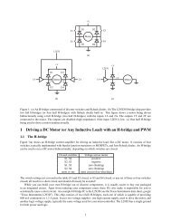
<strong>dsPIC33FJ12MC201</strong>/<strong>202</strong>2.0 GUIDELINES FOR GETTINGSTARTED WITH 16-BITDIGITAL SIGNALCONTROLLERSNote:This data sheet summarizes the featuresof the <strong>dsPIC33FJ12MC201</strong>/<strong>202</strong> family ofdevices. It is not intended to be acomprehensive reference source. Tocomplement the information in this datasheet, refer to the “dsPIC33F FamilyReference Manual”, which is availablefrom the <strong>Microchip</strong> web site(www.microchip.com).2.1 Basic Connection RequirementsGetting started with the <strong>dsPIC33FJ12MC201</strong>/<strong>202</strong>family of 16-bit Digital Signal Controllers (DSC)requires attention to a minimal set of device pinconnections before proceeding with development. Thefollowing is a list of pin names, which must always beconnected:• All VDD and VSS pins(see Section 2.2 “Decoupling Capacitors”)• All AVDD and AVSS pins (regardless if ADC moduleis not used)(see Section 2.2 “Decoupling Capacitors”)• VCAP(see Section 2.3 “CPU Logic Filter CapacitorConnection (VCAP)”)• MCLR pin(see Section 2.4 “Master Clear (MCLR) Pin”)• PGECx/PGEDx pins used for In-Circuit SerialProgramming (ICSP) and debugging purposes(see Section 2.5 “ICSP Pins”)• OSC1 and OSC2 pins when external oscillatorsource is used(see Section 2.6 “External Oscillator Pins”)Additionally, the following pins may be required:• VREF+/VREF- pins used when external voltagereference for ADC module is implementedNote: The AVDD and AVSS pins must beconnected independent of the ADCvoltage reference source.2.2 Decoupling CapacitorsThe use of decoupling capacitors on every pair ofpower supply pins, such as VDD, VSS, AVDD, andAVSS is required.Consider the following criteria when using decouplingcapacitors:• Value and type of capacitor: Recommendationof 0.1 µF (100 nF), 10-20V. This capacitor shouldbe a low-ESR and have resonance frequency inthe range of 20 MHz and higher. It isrecommended that ceramic capacitors be used.• Placement on the printed circuit board: Thedecoupling capacitors should be placed as closeto the pins as possible. It is recommended toplace the capacitors on the same side of theboard as the device. If space is constricted, thecapacitor can be placed on another layer on thePCB using a via; however, ensure that the tracelength from the pin to the capacitor is withinone-quarter inch (6 mm) in length.• Handling high frequency noise: If the board isexperiencing high frequency noise, upward oftens of MHz, add a second ceramic-type capacitorin parallel to the above described decouplingcapacitor. The value of the second capacitor canbe in the range of 0.01 µF to 0.001 µF. Place thissecond capacitor next to the primary decouplingcapacitor. In high-speed circuit designs, considerimplementing a decade pair of capacitances asclose to the power and ground pins as possible.For example, 0.1 µF in parallel with 0.001 µF.• Maximizing performance: On the board layoutfrom the power supply circuit, run the power andreturn traces to the decoupling capacitors first,and then to the device pins. This ensures that thedecoupling capacitors are first in the power chain.Equally important is to keep the trace lengthbetween the capacitor and the power pins to aminimum thereby reducing PCB track inductance.© 2007-2011 <strong>Microchip</strong> Technology Inc. DS70265E-page 15
<strong>dsPIC33FJ12MC201</strong>/<strong>202</strong>FIGURE 2-1:VDDRCR10.1 µFCeramic10 µFTantalumMCLRVSSVDD10 ΩAVDDRECOMMENDEDMINIMUM CONNECTIONVCAPdsPIC33FAVSS0.1 µFCeramicVDDVDDVSSVSS0.1 µFCeramicVDDVSS0.1 µFCeramic0.1 µFCeramic2.4 Master Clear (MCLR) PinThe MCLR pin provides for two specific devicefunctions:• Device Reset• Device programming and debuggingDuring device programming and debugging, theresistance and capacitance that can be added to thepin must be considered. Device programmers anddebuggers drive the MCLR pin. Consequently,specific voltage levels (VIH and VIL) and fast signaltransitions must not be adversely affected. Therefore,specific values of R and C will need to be adjustedbased on the application and PCB requirements.For example, as shown in Figure 2-2, it isrecommended that the capacitor C, be isolated fromthe MCLR pin during programming and debuggingoperations.Place the components shown in Figure 2-2 withinone-quarter inch (6 mm) from the MCLR pin.2.2.1 TANK CAPACITORSOn boards with power traces running longer than sixinches in length, it is suggested to use a tank capacitorfor integrated circuits including DSCs to supply a localpower source. The value of the tank capacitor shouldbe determined based on the trace resistance that connectsthe power supply source to the device, and themaximum current drawn by the device in the application.In other words, select the tank capacitor so that itmeets the acceptable voltage sag at the device. Typicalvalues range from 4.7 µF to 47 µF.FIGURE 2-2:VDDRJPCEXAMPLE OF MCLR PINCONNECTIONSR1MCLRdsPIC33F2.3 CPU Logic Filter CapacitorConnection (VCAP)A low-ESR (< 5 Ohms) capacitor is required on theVCAP pin, which is used to stabilize the voltageregulator output voltage. The VCAP pin must not beconnected to VDD, and must have a capacitor between4.7 µF and 10 µF, 16V connected to ground. The typecan be ceramic or tantalum. Refer to Section 24.0“Electrical Characteristics” for additionalinformation.The placement of this capacitor should be close to theVCAP. It is recommended that the trace length notexceed one-quarter inch (6 mm). Refer to Section 21.2“On-Chip Voltage Regulator” for details.Note 1: R ≤ 10 kΩ is recommended. A suggestedstarting value is 10 kΩ. Ensure that the MCLRpin VIH and VIL specifications are met.2: R1 ≤ 470Ω will limit any current flowing intoMCLR from the external capacitor C, in theevent of MCLR pin breakdown, due toElectrostatic Discharge (ESD) or ElectricalOverstress (EOS). Ensure that the MCLR pinVIH and VIL specifications are met.DS70265E-page 16© 2007-2011 <strong>Microchip</strong> Technology Inc.
<strong>dsPIC33FJ12MC201</strong>/<strong>202</strong>2.5 ICSP PinsThe PGECx and PGEDx pins are used for In-CircuitSerial Programming (ICSP) and debugging purposes.It is recommended to keep the trace lengthbetween the ICSP connector and the ICSP pins on thedevice as short as possible. If the ICSP connector isexpected to experience an ESD event, a series resistoris recommended, with the value in the range of a fewtens of Ohms, not to exceed 100 Ohms.Pull-up resistors, series diodes, and capacitors on thePGECx and PGEDx pins are not recommended as theywill interfere with the programmer/debugger communicationsto the device. If such discrete components arean application requirement, they should be removedfrom the circuit during programming and debugging.Alternately, refer to the AC/DC characteristics and timingrequirements information in the respective deviceFlash programming specification for information oncapacitive loading limits and pin input voltage high (VIH)and input low (VIL) requirements.Ensure that the “Communication Channel Select” (i.e.,PGECx/PGEDx pins) programmed into the devicematches the physical connections for the ICSP toMPLAB ® ICD 2, MPLAB ICD 3, or MPLAB REALICE.For more information on ICD 2, ICD 3, and REAL ICEconnection requirements, refer to the followingdocuments that are available on the <strong>Microchip</strong> website.• “MPLAB ® ICD 2 In-Circuit Debugger User’sGuide” DS51331• “Using MPLAB ® ICD 2” (poster) DS51265• “MPLAB ® ICD 2 Design Advisory” DS51566• “Using MPLAB ® ICD 3” (poster) DS51765• “MPLAB ® ICD 3 Design Advisory” DS51764• “MPLAB ® REAL ICE In-Circuit DebuggerUser’s Guide” DS51616• “Using MPLAB ® REAL ICE” (poster) DS517492.6 External Oscillator PinsMany DSCs have options for at least two oscillators: ahigh-frequency primary oscillator and a low-frequencysecondary oscillator (refer to Section 8.0 “OscillatorConfiguration” for details).The oscillator circuit should be placed on the sameside of the board as the device. Also, place theoscillator circuit close to the respective oscillator pins,not exceeding one-half inch (12 mm) distancebetween them. The load capacitors should be placednext to the oscillator itself, on the same side of theboard. Use a grounded copper pour around theoscillator circuit to isolate them from surroundingcircuits. The grounded copper pour should be routeddirectly to the MCU ground. Do not run any signaltraces or power traces inside the ground pour. Also, ifusing a two-sided board, avoid any traces on theother side of the board where the crystal is placed. Asuggested layout is shown in Figure 2-3.FIGURE 2-3:Main OscillatorGuard RingGuard TraceSecondaryOscillatorSUGGESTED PLACEMENTOF THE OSCILLATORCIRCUIT1314151617181920© 2007-2011 <strong>Microchip</strong> Technology Inc. DS70265E-page 17
<strong>dsPIC33FJ12MC201</strong>/<strong>202</strong>2.7 Oscillator Value Conditions onDevice Start-upIf the PLL of the target device is enabled andconfigured for the device start-up oscillator, themaximum oscillator source frequency must be limitedto 4 MHz < FIN < 8 MHz to comply with device PLLstart-up conditions. This means that if the externaloscillator frequency is outside this range, theapplication must start-up in the FRC mode first. Thedefault PLL settings after a POR with an oscillatorfrequency outside this range will violate the deviceoperating speed.Once the device powers up, the application firmwarecan initialize the PLL SFRs, CLKDIV, and PLLDBF to asuitable value, and then perform a clock switch to theOscillator + PLL clock source. Note that clock switchingmust be enabled in the device Configuration word.2.9 Unused I/OsUnused I/O pins should be configured as outputs anddriven to a logic-low state.Alternately, connect a 1k to 10k resistor between VSSand unused pins and drive the output to logic low.2.8 Configuration of Analog andDigital Pins During ICSPOperationsIf MPLAB ICD 2, MPLAB ICD 3, or MPLAB REAL ICEin-circuit emulator is selected as a debugger, itautomatically initializes all of the A/D input pins (ANx)as “digital” pins, by setting all bits in the AD1PCFGLregister.The bits in the register that correspond to the A/D pinsthat are initialized by MPLAB ICD 2, MPLAB ICD 3, orMPLAB REAL ICE in-circuit emulator, must not becleared by the user application firmware; otherwise,communication errors will result between the debuggerand the device.If your application needs to use certain A/D pins asanalog input pins during the debug session, the userapplication must clear the corresponding bits in theAD1PCFGL register during initialization of the ADCmodule.When MPLAB ICD 2, MPLAB ICD 3, or MPLAB REALICE in-circuit emulator is used as a programmer, theuser application firmware must correctly configure theAD1PCFGL register. Automatic initialization of thisregister is only done during debugger operation.Failure to correctly configure the register(s) will result inall A/D pins being recognized as analog input pins,resulting in the port value being read as a logic ‘0’,which may affect user application functionality.DS70265E-page 18© 2007-2011 <strong>Microchip</strong> Technology Inc.
<strong>dsPIC33FJ12MC201</strong>/<strong>202</strong>3.0 CPUNote 1: This data sheet summarizes the featuresof the <strong>dsPIC33FJ12MC201</strong>/<strong>202</strong> family ofdevices. It is not intended to be acomprehensive reference source. Tocomplement the information in this datasheet, refer to Section 2. “CPU”(DS70204) of the “dsPIC33F/PIC24HFamily Reference Manual”, which isavailable from the <strong>Microchip</strong> website(www.microchip.com).2: Some registers and associated bitsdescribed in this section may not beavailable on all devices. Refer toSection 4.0 “Memory Organization” inthis data sheet for device-specific registerand bit information.The <strong>dsPIC33FJ12MC201</strong>/<strong>202</strong> CPU module has a 16-bit (data) modified Harvard architecture with anenhanced instruction set, including significant supportfor DSP. The CPU has a 24-bit instruction word with avariable length opcode field. The Program Counter(PC) is 23 bits wide and addresses up to 4M x 24 bitsof user program memory space. The actual amount ofprogram memory implemented varies by device. Asingle-cycle instruction prefetch mechanism is used tohelp maintain throughput and provides predictableexecution. All instructions execute in a single cycle,with the exception of instructions that change theprogram flow, the double-word move (MOV.D)instruction and the table instructions. Overhead-freeprogram loop constructs are supported using the DOand REPEAT instructions, both of which areinterruptible at any point.The <strong>dsPIC33FJ12MC201</strong>/<strong>202</strong> devices have sixteen,16-bit working registers in the programmer’s model.Each of the working registers can serve as a data,address, or address offset register. The 16th workingregister (W15) operates as a software Stack Pointer(SP) for interrupts and calls.There are two classes of instruction in the<strong>dsPIC33FJ12MC201</strong>/<strong>202</strong> devices: MCU and DSP.These two instruction classes are seamlesslyintegrated into a single CPU. The instruction setincludes many addressing modes and is designed foroptimum C compiler efficiency. For most instructions,<strong>dsPIC33FJ12MC201</strong>/<strong>202</strong> devices are capable of executinga data (or program data) memory read, a workingregister (data) read, a data memory write, and aprogram (instruction) memory read per instructioncycle. As a result, three parameter instructions can besupported, allowing A + B = C operations to beexecuted in a single cycle.A block diagram of the CPU is shown in Figure 3-1, andthe programmer’s model for the <strong>dsPIC33FJ12MC201</strong>/<strong>202</strong> is shown in Figure 3-2.3.1 <strong>Data</strong> Addressing OverviewThe data space can be addressed as 32K words or64 Kbytes and is split into two blocks, referred to as Xand Y data memory. Each memory block has its ownindependent Address Generation Unit (AGU). TheMCU class of instructions operates solely through theX memory AGU, which accesses the entire memorymap as one linear data space. Certain DSP instructionsoperate through the X and Y AGUs to support dualoperand reads, which splits the data address spaceinto two parts. The X and Y data space boundary isdevice-specific.Overhead-free circular buffers (Modulo Addressingmode) are supported in both X and Y address spaces.The Modulo Addressing removes the softwareboundary checking overhead for DSP algorithms.Furthermore, the X AGU circular addressing can beused with any of the MCU class of instructions. The XAGU also supports Bit-Reversed Addressing to greatlysimplify input or output data reordering for radix-2 FFTalgorithms.The upper 32 Kbytes of the data space memory mapcan optionally be mapped into program space at any16K program word boundary defined by the 8-bitProgram Space Visibility Page (PSVPAG) register. Theprogram-to-data-space mapping feature lets anyinstruction access program space as if it were dataspace.3.2 DSP Engine OverviewThe DSP engine features a high-speed 17-bit by 17-bitmultiplier, a 40-bit ALU, two 40-bit saturatingaccumulators, and a 40-bit bidirectional barrel shifter.The barrel shifter is capable of shifting a 40-bit value upto 16 bits right or left, in a single cycle. The DSP instructionsoperate seamlessly with all other instructions andhave been designed for optimal real-time performance.The MAC instruction and other associated instructionscan concurrently fetch two data operands from memory,while multiplying two W registers and accumulatingand optionally saturating the result in the same cycle.This instruction functionality requires that the RAM dataspace be split for these instructions and linear for allothers. <strong>Data</strong> space partitioning is achieved in a transparentand flexible manner through dedicating certainworking registers to each address space.3.3 Special MCU FeaturesThe <strong>dsPIC33FJ12MC201</strong>/<strong>202</strong> features a 17-bit by 17-bit single-cycle multiplier that is shared by both theMCU ALU and DSP engine. The multiplier can performsigned, unsigned and mixed-sign multiplication. Usinga 17-bit by 17-bit multiplier for 16-bit by 16-bitmultiplication not only allows you to perform mixed-signmultiplication, it also achieves accurate results forspecial operations, such as (-1.0) x (-1.0).© 2007-2011 <strong>Microchip</strong> Technology Inc. DS70265E-page 19
<strong>dsPIC33FJ12MC201</strong>/<strong>202</strong>The <strong>dsPIC33FJ12MC201</strong>/<strong>202</strong> supports 16/16 and 32/16 divide operations, both fractional and integer. Alldivide instructions are iterative operations. They mustbe executed within a REPEAT loop, resulting in a totalexecution time of 19 instruction cycles. The divideoperation can be interrupted during any of those19 cycles without loss of data.A 40-bit barrel shifter is used to perform up to a 16-bitleft or right shift in a single cycle. The barrel shifter canbe used by both MCU and DSP instructions.FIGURE 3-1:<strong>dsPIC33FJ12MC201</strong>/<strong>202</strong> CPU CORE BLOCK DIAGRAMPSV and Table<strong>Data</strong> AccessControl BlockY <strong>Data</strong> BusInterruptControllerX <strong>Data</strong> Bus8161616162323PCU PCH PCLProgram CounterStack LoopControl ControlLogic Logic<strong>Data</strong> LatchX RAMAddressLatch<strong>Data</strong> LatchY RAMAddressLatch16231616Address LatchAddress Generator UnitsProgram MemoryEA MUX<strong>Data</strong> Latch24ROM Latch16 16InstructionDecode andControlInstruction RegLiteral <strong>Data</strong>Control Signalsto Various Blocks16DSP EngineDivide Support16 x 16W Register Array1616-bit ALU16To Peripheral ModulesDS70265E-page 20© 2007-2011 <strong>Microchip</strong> Technology Inc.
<strong>dsPIC33FJ12MC201</strong>/<strong>202</strong>FIGURE 3-2:<strong>dsPIC33FJ12MC201</strong>/<strong>202</strong> PROGRAMMER’S MODELD15D0W0/WREGW1W2PUSH.S ShadowDO ShadowDSP OperandRegistersDSP AddressRegistersW3W4W5W6W7W8W9W10W11W12/DSP OffsetW13/DSP Write BackW14/Frame PointerW15/Stack PointerWorking RegistersLegendSPLIMStack Pointer Limit RegisterAD39AD31AD15AD0DSPAccumulatorsACCAACCBPC22PC00Program Counter7 0TBLPAG<strong>Data</strong> Table Page Address7 0PSVPAGProgram Space Visibility Page Address15 0RCOUNTREPEAT Loop Counter15 0DCOUNTDO Loop Counter22 0DOSTARTDO Loop Start Address22DOENDDO Loop End Address15 0CORCONCore Configuration RegisterOA OB SA SBOAB SABDA DC IPL2 IPL1 IPL0 RA NOVZCSTATUS RegisterSRHSRL© 2007-2011 <strong>Microchip</strong> Technology Inc. DS70265E-page 21
<strong>dsPIC33FJ12MC201</strong>/<strong>202</strong>3.4 CPU Control RegistersREGISTER 3-1:SR: CPU STATUS REGISTERR-0 R-0 R/C-0 R/C-0 R-0 R/C-0 R -0 R/W-0OA OB SA (1) SB (1) OAB SAB DA DCbit 15 bit 8R/W-0 (2) R/W-0 (3) R/W-0 (3) R-0 R/W-0 R/W-0 R/W-0 R/W-0IPL (2) RA N OV Z Cbit 7 bit 0Legend:C = Clear only bit R = Readable bit U = Unimplemented bit, read as ‘0’S = Set only bit W = Writable bit -n = Value at POR‘1’ = Bit is set ‘0’ = Bit is cleared x = Bit is unknownbit 15OA: Accumulator A Overflow Status bit1 = Accumulator A overflowed0 = Accumulator A has not overflowedbit 14 OB: Accumulator B Overflow Status bit1 = Accumulator B overflowed0 = Accumulator B has not overflowedbit 13 SA: Accumulator A Saturation ‘Sticky’ Status bit (1)1 = Accumulator A is saturated or has been saturated at some time0 = Accumulator A is not saturatedbit 12 SB: Accumulator B Saturation ‘Sticky’ Status bit (1)bit 11bit 10bit 9bit 81 = Accumulator B is saturated or has been saturated at some time0 = Accumulator B is not saturatedOAB: OA || OB Combined Accumulator Overflow Status bit1 = Accumulators A or B have overflowed0 = Neither Accumulators A or B have overflowedSAB: SA || SB Combined Accumulator ‘Sticky’ Status bit1 = Accumulators A or B are saturated or have been saturated at some time in the past0 = Neither Accumulator A or B are saturatedThis bit may be read or cleared (not set). Clearing this bit will clear SA and SB.DA: DO Loop Active bit1 = DO loop in progress0 = DO loop not in progressDC: MCU ALU Half Carry/Borrow bit1 = A carry-out from the 4th low-order bit (for byte-sized data) or 8th low-order bit (for word-sized data)of the result occurred0 = No carry-out from the 4th low-order bit (for byte-sized data) or 8th low-order bit (for word-sizeddata) of the result occurredNote 1: This bit can be read or cleared (not set).2: The IPL bits are concatenated with the IPL bit (CORCON) to form the CPU Interrupt PriorityLevel. The value in parentheses indicates the IPL if IPL = 1. User interrupts are disabled whenIPL = 1.3: The IPL Status bits are read-only when NSTDIS = 1 (INTCON1).DS70265E-page 22© 2007-2011 <strong>Microchip</strong> Technology Inc.
<strong>dsPIC33FJ12MC201</strong>/<strong>202</strong>REGISTER 3-1:SR: CPU STATUS REGISTER (CONTINUED)bit 7-5 IPL: CPU Interrupt Priority Level Status bits (2)bit 4bit 3bit 2bit 1bit 0111 = CPU Interrupt Priority Level is 7 (15), user interrupts disabled110 = CPU Interrupt Priority Level is 6 (14)101 = CPU Interrupt Priority Level is 5 (13)100 = CPU Interrupt Priority Level is 4 (12)011 = CPU Interrupt Priority Level is 3 (11)010 = CPU Interrupt Priority Level is 2 (10)001 = CPU Interrupt Priority Level is 1 (9)000 = CPU Interrupt Priority Level is 0 (8)RA: REPEAT Loop Active bit1 = REPEAT loop in progress0 = REPEAT loop not in progressN: MCU ALU Negative bit1 = Result was negative0 = Result was non-negative (zero or positive)OV: MCU ALU Overflow bitThis bit is used for signed arithmetic (2’s complement). It indicates an overflow of a magnitude thatcauses the sign bit to change state.1 = Overflow occurred for signed arithmetic (in this arithmetic operation)0 = No overflow occurredZ: MCU ALU Zero bit1 = An operation that affects the Z bit has set it at some time in the past0 = The most recent operation that affects the Z bit has cleared it (i.e., a non-zero result)C: MCU ALU Carry/Borrow bit1 = A carry-out from the Most Significant bit of the result occurred0 = No carry-out from the Most Significant bit of the result occurredNote 1: This bit can be read or cleared (not set).2: The IPL bits are concatenated with the IPL bit (CORCON) to form the CPU Interrupt PriorityLevel. The value in parentheses indicates the IPL if IPL = 1. User interrupts are disabled whenIPL = 1.3: The IPL Status bits are read-only when NSTDIS = 1 (INTCON1).© 2007-2011 <strong>Microchip</strong> Technology Inc. DS70265E-page 23
<strong>dsPIC33FJ12MC201</strong>/<strong>202</strong>REGISTER 3-2:CORCON: CORE CONTROL REGISTERU-0 U-0 U-0 R/W-0 R/W-0 R-0 R-0 R-0— — — US EDT (1) DLbit 15 bit 8R/W-0 R/W-0 R/W-1 R/W-0 R/C-0 R/W-0 R/W-0 R/W-0SATA SATB SATDW ACCSAT IPL3 (2) PSV RND IFbit 7 bit 0Legend:C = Clear only bitR = Readable bit W = Writable bit -n = Value at POR ‘1’ = Bit is set0’ = Bit is cleared ‘x = Bit is unknown U = Unimplemented bit, read as ‘0’bit 15-13 Unimplemented: Read as ‘0’bit 12 US: DSP Multiply Unsigned/Signed Control bit1 = DSP engine multiplies are unsigned0 = DSP engine multiplies are signedbit 11 EDT: Early DO Loop Termination Control bit (1)1 = Terminate executing DO loop at end of current loop iteration0 = No effectbit 10-8 DL: DO Loop Nesting Level Status bits111 = 7 DO loops active•••001 = 1 DO loop active000 = 0 DO loops activebit 7SATA: ACCA Saturation Enable bit1 = Accumulator A saturation enabled0 = Accumulator A saturation disabledbit 6SATB: ACCB Saturation Enable bit1 = Accumulator B saturation enabled0 = Accumulator B saturation disabledbit 5SATDW: <strong>Data</strong> Space Write from DSP Engine Saturation Enable bit1 = <strong>Data</strong> space write saturation enabled0 = <strong>Data</strong> space write saturation disabledbit 4ACCSAT: Accumulator Saturation Mode Select bit1 = 9.31 saturation (super saturation)0 = 1.31 saturation (normal saturation)bit 3 IPL3: CPU Interrupt Priority Level Status bit 3 (2)bit 2bit 1bit 01 = CPU interrupt priority level is greater than 70 = CPU interrupt priority level is 7 or lessPSV: Program Space Visibility in <strong>Data</strong> Space Enable bit1 = Program space visible in data space0 = Program space not visible in data spaceRND: Rounding Mode Select bit1 = Biased (conventional) rounding enabled0 = Unbiased (convergent) rounding enabledIF: Integer or Fractional Multiplier Mode Select bit1 = Integer mode enabled for DSP multiply ops0 = Fractional mode enabled for DSP multiply opsNote 1: This bit will always read as ‘0’.2: The IPL3 bit is concatenated with the IPL bits (SR) to form the CPU interrupt priority level.DS70265E-page 24© 2007-2011 <strong>Microchip</strong> Technology Inc.
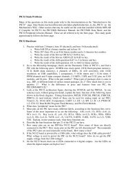
<strong>dsPIC33FJ12MC201</strong>/<strong>202</strong>3.5 Arithmetic Logic Unit (ALU)The <strong>dsPIC33FJ12MC201</strong>/<strong>202</strong> ALU is 16 bits wide andis capable of addition, subtraction, bit shifts, and logicoperations. Unless otherwise mentioned, arithmeticoperations are 2’s complement in nature. Dependingon the operation, the ALU can affect the values of theCarry (C), Zero (Z), Negative (N), Overflow (OV), andDigit Carry (DC) Status bits in the SR register. The Cand DC Status bits operate as Borrow and Digit Borrowbits, respectively, for subtraction operations.The ALU can perform 8-bit or 16-bit operations,depending on the mode of the instruction that is used.<strong>Data</strong> for the ALU operation can come from the Wregister array or data memory, depending on theaddressing mode of the instruction. Likewise, outputdata from the ALU can be written to the W register arrayor a data memory location.Refer to the “16-bit MCU and DSC Programmer’s ReferenceManual” (DS70157) for information on the SRbits affected by each instruction.The <strong>dsPIC33FJ12MC201</strong>/<strong>202</strong> CPU incorporates hardwaresupport for both multiplication and division. Thisincludes a dedicated hardware multiplier and supporthardware for 16-bit-divisor division.3.5.1 MULTIPLIERUsing the high-speed 17-bit x 17-bit multiplier of theDSP engine, the ALU supports unsigned, signed ormixed-sign operation in several MCU multiplicationmodes:• 16-bit x 16-bit signed• 16-bit x 16-bit unsigned• 16-bit signed x 5-bit (literal) unsigned• 16-bit unsigned x 16-bit unsigned• 16-bit unsigned x 5-bit (literal) unsigned• 16-bit unsigned x 16-bit signed• 8-bit unsigned x 8-bit unsigned3.5.2 DIVIDERThe divide block supports 32-bit/16-bit and 16-bit/16-bitsigned and unsigned integer divide operations with thefollowing data sizes:1. 32-bit signed/16-bit signed divide2. 32-bit unsigned/16-bit unsigned divide3. 16-bit signed/16-bit signed divide4. 16-bit unsigned/16-bit unsigned divideThe quotient for all divide instructions ends up in W0and the remainder in W1. 16-bit signed and unsignedDIV instructions can specify any W register for boththe 16-bit divisor (Wn) and any W register (aligned)pair (W(m + 1):Wm) for the 32-bit dividend. The dividealgorithm takes one cycle per bit of divisor, so both32-bit/16-bit and 16-bit/16-bit instructions take thesame number of cycles to execute.3.6 DSP EngineThe DSP engine consists of a high-speed 17-bit x17-bit multiplier, a barrel shifter and a 40-bit adder/subtracter (with two target accumulators, round andsaturation logic).The <strong>dsPIC33FJ12MC201</strong>/<strong>202</strong> is a single-cycle instructionflow architecture; therefore, concurrent operationof the DSP engine with MCU instruction flow is not possible.However, some MCU ALU and DSP engineresources can be used concurrently by the sameinstruction (e.g., ED, EDAC).The DSP engine can also perform inherent accumulator-to-accumulatoroperations that require no additionaldata. These instructions are ADD, SUB, and NEG.The DSP engine has options selected through bits inthe CPU Core Control register (CORCON), as listedbelow:• Fractional or integer DSP multiply (IF)• Signed or unsigned DSP multiply (US)• Conventional or convergent rounding (RND)• Automatic saturation on/off for ACCA (SATA)• Automatic saturation on/off for ACCB (SATB)• Automatic saturation on/off for writes to datamemory (SATDW)• Accumulator Saturation mode selection (ACC-SAT)A block diagram of the DSP engine is shown inFigure 3-3.TABLE 3-1:InstructionDSP INSTRUCTIONSSUMMARYAlgebraicOperationACC WriteBackCLR A = 0 YesED A = (x – y) 2 NoEDAC A = A + (x – y) 2 NoMAC A = A + (x * y) YesMAC A = A + x 2 NoMOVSAC No change in A YesMPY A = x * y NoMPY A = x 2 NoMPY.N A = – x * y NoMSC A = A – x * y Yes© 2007-2011 <strong>Microchip</strong> Technology Inc. DS70265E-page 25
<strong>dsPIC33FJ12MC201</strong>/<strong>202</strong>FIGURE 3-3:DSP ENGINE BLOCK DIAGRAM40Carry/Borrow Out40-bit Accumulator A40-bit Accumulator BSaturate40RoundLogicSaturate16Carry/Borrow InAdderNegate40 4040BarrelShifter1640Sign-ExtendX <strong>Data</strong> BusY <strong>Data</strong> Bus333232Zero Backfill1617-bitMultiplier/Scaler16 16To/From W ArrayDS70265E-page 26© 2007-2011 <strong>Microchip</strong> Technology Inc.
<strong>dsPIC33FJ12MC201</strong>/<strong>202</strong>3.6.1 MULTIPLIERThe 17-bit x 17-bit multiplier is capable of signed orunsigned operation and can multiplex its output using ascaler to support either 1.31 fractional (Q31) or 32-bitinteger results. Unsigned operands are zero-extendedinto the 17th bit of the multiplier input value. Signedoperands are sign-extended into the 17th bit of themultiplier input value. The output of the 17-bit x 17-bitmultiplier/scaler is a 33-bit value that is sign-extendedto 40 bits. Integer data is inherently represented as asigned 2’s complement value, where the Most Significantbit (MSb) is defined as a sign bit. The range of anN-bit 2’s complement integer is -2 N-1 to 2 N-1 – 1.• For a 16-bit integer, the data range is -32768(0x8000) to 32767 (0x7FFF) including 0.• For a 32-bit integer, the data range is-2,147,483,648 (0x8000 0000) to 2,147,483,647(0x7FFF FFFF).When the multiplier is configured for fractionalmultiplication, the data is represented as a 2’scomplement fraction, where the MSb is defined as asign bit and the radix point is implied to lie just after thesign bit (QX format). The range of an N-bit 2’scomplement fraction with this implied radix point is -1.0to (1 – 2 1-N ). For a 16-bit fraction, the Q15 data rangeis -1.0 (0x8000) to 0.999969482 (0x7FFF) including 0and has a precision of 3.01518x10 -5 . In Fractionalmode, the 16 x 16 multiply operation generates a 1.31product that has a precision of 4.65661 x 10 -10 .The same multiplier is used to support the MCUmultiply instructions, which include integer 16-bitsigned, unsigned and mixed sign multiply operations.The MUL instruction can be directed to use byte- orword-sized operands. Byte operands will direct a 16-bitresult, and word operands will direct a 32-bit result tothe specified register(s) in the W array.3.6.2 DATA ACCUMULATORS ANDADDER/SUBTRACTERThe data accumulator consists of a 40-bit adder/subtracter with automatic sign extension logic. It canselect one of two accumulators (A or B) as its preaccumulationsource and post-accumulationdestination. For the ADD and LAC instructions, the datato be accumulated or loaded can be optionally scaledusing the barrel shifter prior to accumulation.3.6.2.1 Adder/Subtracter, Overflow andSaturationThe adder/subtracter is a 40-bit adder with an optionalzero input into one side, and either true or complementdata into the other input.• In the case of addition, the Carry/Borrow input isactive-high and the other input is true data (notcomplemented).• In the case of subtraction, the Carry/Borrow inputis active-low and the other input is complemented.The adder/subtracter generates Overflow Status bits,SA/SB and OA/OB, which are latched and reflected inthe STATUS register:• Overflow from bit 39: this is a catastrophicoverflow in which the sign of the accumulator isdestroyed.• Overflow into guard bits 32 through 39: this is arecoverable overflow. This bit is set whenever allthe guard bits are not identical to each other.The adder has an additional saturation block thatcontrols accumulator data saturation, if selected. Ituses the result of the adder, the Overflow Status bitsdescribed previously and the SAT(CORCON) and ACCSAT (CORCON) modecontrol bits to determine when and to what value, tosaturate.Six STATUS register bits support saturation andoverflow:• OA: ACCA overflowed into guard bits• OB: ACCB overflowed into guard bits• SA: ACCA saturated (bit 31 overflow andsaturation)orACCA overflowed into guard bits andsaturated (bit 39 overflow and saturation)• SB: ACCB saturated (bit 31 overflow andsaturation)orACCB overflowed into guard bits andsaturated (bit 39 overflow and saturation)• OAB: Logical OR of OA and OB• SAB: Logical OR of SA and SBThe OA and OB bits are modified each time datapasses through the adder/subtracter. When set, theyindicate that the most recent operation has overflowedinto the accumulator guard bits (bits 32 through 39).The OA and OB bits can also optionally generate anarithmetic warning trap when OA and OB are set andthe corresponding Overflow Trap Flag Enable bits(OVATE, OVBTE) in the INTCON1 register are set(refer to Section 7.0 “Interrupt Controller”). Thisallows the user application to take immediate action; forexample, to correct system gain.© 2007-2011 <strong>Microchip</strong> Technology Inc. DS70265E-page 27
<strong>dsPIC33FJ12MC201</strong>/<strong>202</strong>The SA and SB bits are modified each time datapasses through the adder/subtracter, but can only becleared by the user application. When set, they indicatethat the accumulator has overflowed its maximumrange (bit 31 for 32-bit saturation or bit 39 for 40-bitsaturation) and will be saturated (if saturation isenabled). When saturation is not enabled, SA and SBdefault to bit 39 overflow, and therefore, indicate that acatastrophic overflow has occurred. If the COVTE bit inthe INTCON1 register is set, the SA and SB bits willgenerate an arithmetic warning trap when saturation isdisabled.The Overflow and Saturation Status bits can optionallybe viewed in the STATUS Register (SR) as the logicalOR of OA and OB (in bit OAB) and the logical OR of SAand SB (in bit SAB). Programmers can check one bit inthe STATUS register to determine whether eitheraccumulator has overflowed, or one bit to determinewhether either accumulator has saturated. This isuseful for complex number arithmetic, which typicallyuses both accumulators.The device supports three Saturation and Overflowmodes:• Bit 39 Overflow and Saturation:When bit 39 overflow and saturation occurs, thesaturation logic loads the maximally positive 9.31value (0x7FFFFFFFFF) or maximally negative 9.31value (0x8000000000) into the target accumulator.The SA or SB bit is set and remains set untilcleared by the user application. This condition isreferred to as ‘super saturation’ and provides protectionagainst erroneous data or unexpected algorithmproblems (such as gain calculations).• Bit 31 Overflow and Saturation:When bit 31 overflow and saturation occurs, thesaturation logic then loads the maximally positive1.31 value (0x007FFFFFFF) or maximally negative1.31 value (0x0080000000) into the targetaccumulator. The SA or SB bit is set and remainsset until cleared by the user application. Whenthis Saturation mode is in effect, the guard bits arenot used, so the OA, OB or OAB bits are neverset.• Bit 39 Catastrophic Overflow:The bit 39 Overflow Status bit from the adder isused to set the SA or SB bit, which remains setuntil cleared by the user application. No saturationoperation is performed, and the accumulator isallowed to overflow, destroying its sign. If theCOVTE bit in the INTCON1 register is set, acatastrophic overflow can initiate a trap exception.3.6.3 ACCUMULATOR ‘WRITE BACK’The MAC class of instructions (with the exception ofMPY, MPY.N, ED, and EDAC) can optionally write arounded version of the high word (bits 31 through 16)of the accumulator which is not targeted by the instructioninto data space memory. The write is performedacross the X bus into combined X and Y addressspace. The following addressing modes are supported:• W13, Register Direct:The rounded contents of the non-targetaccumulator are written into W13 as a1.15 fraction.• [W13] + = 2, Register Indirect with Post-Increment:The rounded contents of the non-target accumulatorare written into the address pointed to byW13 as a 1.15 fraction. W13 is then incrementedby 2 (for a word write).DS70265E-page 28© 2007-2011 <strong>Microchip</strong> Technology Inc.
<strong>dsPIC33FJ12MC201</strong>/<strong>202</strong>3.6.3.1 Round LogicThe round logic is a combinational block that performsa conventional (biased) or convergent (unbiased)round function during an accumulator write (store). TheRound mode is determined by the state of the RND bitin the CORCON register. It generates a 16-bit, 1.15data value that is passed to the data space writesaturation logic. If rounding is not indicated by theinstruction, a truncated 1.15 data value is stored andthe least significant word (lsw) is simply discarded.Conventional rounding will zero-extend bit 15 of theaccumulator and will add it to the ACCxH word (bits 16through 31 of the accumulator).• If the ACCxL word (bits 0 through 15 of the accumulator)is between 0x8000 and 0xFFFF (0x8000included), ACCxH is incremented.• If ACCxL is between 0x0000 and 0x7FFF, ACCxHis left unchanged.A consequence of this algorithm is that over a successionof random rounding operations, the value tends tobe biased slightly positive.Convergent (or unbiased) rounding operates in thesame manner as conventional rounding, except whenACCxL equals 0x8000. In this case, the LeastSignificant bit (LSb), bit 16 of the accumulator, ofACCxH is examined:• If it is ‘1’, ACCxH is incremented.• If it is ‘0’, ACCxH is not modified.Assuming that bit 16 is effectively random in nature,this scheme removes any rounding bias that mayaccumulate.The SAC and SAC.R instructions store either atruncated (SAC), or rounded (SAC.R) version of thecontents of the target accumulator to data memory viathe X bus, subject to data saturation (seeSection 3.6.3.2 “<strong>Data</strong> Space Write Saturation”). Forthe MAC class of instructions, the accumulator writebackoperation functions in the same manner,addressing combined MCU (X and Y) data spacethough the X bus. For this class of instructions, the datais always subject to rounding.3.6.3.2 <strong>Data</strong> Space Write SaturationIn addition to adder/subtracter saturation, writes to dataspace can also be saturated, but without affecting thecontents of the source accumulator. The data spacewrite saturation logic block accepts a 16-bit, 1.15fractional value from the round logic block as its input,together with overflow status from the original source(accumulator) and the 16-bit round adder. These inputsare combined and used to select the appropriate 1.15fractional value as output to write to data spacememory.If the SATDW bit in the CORCON register is set, data(after rounding or truncation) is tested for overflow andadjusted accordingly:• For input data greater than 0x007FFF, datawritten to memory is forced to the maximumpositive 1.15 value, 0x7FFF.• For input data less than 0xFF8000, data written tomemory is forced to the maximum negative 1.15value, 0x8000.The MSb of the source (bit 39) is used to determine thesign of the operand being tested.If the SATDW bit in the CORCON register is not set, theinput data is always passed through unmodified underall conditions.3.6.4 BARREL SHIFTERThe barrel shifter can perform up to 16-bit arithmetic orlogic right shifts, or up to 16-bit left shifts, in a singlecycle. The source can be either of the two DSPaccumulators or the X bus (to support multi-bit shifts ofregister or memory data).The shifter requires a signed binary value to determineboth the magnitude (number of bits) and direction of theshift operation. A positive value shifts the operand right.A negative value shifts the operand left. A value of ‘0’does not modify the operand.The barrel shifter is 40 bits wide, thereby obtaining a40-bit result for DSP shift operations and a 16-bit resultfor MCU shift operations. <strong>Data</strong> from the X bus ispresented to the barrel shifter between bit positions 16and 31 for right shifts, and between bit positions 0 and16 for left shifts.© 2007-2011 <strong>Microchip</strong> Technology Inc. DS70265E-page 29
<strong>dsPIC33FJ12MC201</strong>/<strong>202</strong>NOTES:DS70265E-page 30© 2007-2011 <strong>Microchip</strong> Technology Inc.
<strong>dsPIC33FJ12MC201</strong>/<strong>202</strong>4.0 MEMORY ORGANIZATIONNote:This data sheet summarizes the featuresof the <strong>dsPIC33FJ12MC201</strong>/<strong>202</strong> family ofdevices. It is not intended to be acomprehensive reference source. Tocomplement the information in this datasheet, refer to Section 4. “ProgramMemory” (DS70<strong>202</strong>) of the “dsPIC33F/PIC24H Family Reference Manual”, whichis available from the <strong>Microchip</strong> website(www.microchip.com).The <strong>dsPIC33FJ12MC201</strong>/<strong>202</strong> architecture featuresseparate program and data memory spaces andbuses. This architecture also allows the direct accessof program memory from the data space during codeexecution.4.1 Program Address SpaceThe program address memory space of the<strong>dsPIC33FJ12MC201</strong>/<strong>202</strong> devices is 4M instructions.The space is addressable by a 24-bit value derivedeither from the 23-bit Program Counter (PC) duringprogram execution, or from table operation or dataspace remapping as described in Section 4.6“Interfacing Program and <strong>Data</strong> Memory Spaces”.User application access to the program memory spaceis restricted to the lower half of the address range(0x000000 to 0x7FFFFF). The exception is the use ofTBLRD/TBLWT operations, which use TBLPAG topermit access to the Configuration bits and Device IDsections of the configuration memory space.The memory map for the <strong>dsPIC33FJ12MC201</strong>/<strong>202</strong>family of devices is shown in Figure 4-1.FIGURE 4-1:PROGRAM MEMORY MAP FOR <strong>dsPIC33FJ12MC201</strong>/<strong>202</strong> DEVICESConfiguration Memory Space User Memory Space<strong>dsPIC33FJ12MC201</strong>/<strong>202</strong>GOTO InstructionReset AddressInterrupt Vector TableReservedAlternate Vector TableUser ProgramFlash Memory(4K instructions)Unimplemented(Read ‘0’s)ReservedDevice ConfigurationRegistersReserved0x0000000x0000020x0000040x0000FE0x0001000x0001040x0001FE0x0002000x001FFE0x0020000x7FFFFE0x8000000xF7FFFE0xF800000xF800170xF80018DEVID (2)0xFEFFFE0xFF00000xFFFFFE© 2007-2011 <strong>Microchip</strong> Technology Inc. DS70265E-page 31
<strong>dsPIC33FJ12MC201</strong>/<strong>202</strong>4.1.1 PROGRAM MEMORYORGANIZATIONThe program memory space is organized in wordaddressableblocks. Although it is treated as 24 bitswide, it is more appropriate to think of each address ofthe program memory as a lower and upper word, withthe upper byte of the upper word being unimplemented.The lower word always has an even address, while theupper word has an odd address (Figure 4-2).Program memory addresses are always word-alignedon the lower word, and addresses are incremented ordecremented by two during code execution. Thisarrangement provides compatibility with data memoryspace addressing and makes data in the programmemory space accessible.4.1.2 INTERRUPT AND TRAP VECTORSAll <strong>dsPIC33FJ12MC201</strong>/<strong>202</strong> devices reserve theaddresses between 0x00000 and 0x000200 for hardcodedprogram execution vectors. A hardware Resetvector is provided to redirect code execution from thedefault value of the PC on device Reset to the actualstart of code. A GOTO instruction is programmed by theuser application at 0x000000, with the actual addressfor the start of code at 0x000002.<strong>dsPIC33FJ12MC201</strong>/<strong>202</strong> devices also have twointerrupt vector tables, located from 0x000004 to0x0000FF and 0x000100 to 0x0001FF. These vectortables allow each of the device interrupt sources to behandled by separate Interrupt Service Routines (ISRs).A more detailed discussion of the interrupt vectortables is provided in Section 7.1 “Interrupt VectorTable”.FIGURE 4-2:PROGRAM MEMORY ORGANIZATIONmswAddressmost significant word (msw)least significant word (lsw)PC Address(lsw Address)0x0000010x0000030x0000050x000007000000000000000000000000000000002316800x0000000x0000020x0000040x000006Program Memory‘Phantom’ Byte(read as ‘0’)Instruction WidthDS70265E-page 32© 2007-2011 <strong>Microchip</strong> Technology Inc.
<strong>dsPIC33FJ12MC201</strong>/<strong>202</strong>4.2 <strong>Data</strong> Address SpaceThe <strong>dsPIC33FJ12MC201</strong>/<strong>202</strong> CPU has a separate 16-bit-wide data memory space. The data space isaccessed using separate Address Generation Units(AGUs) for read and write operations. The datamemory maps is shown in Figure 4-3.All Effective Addresses (EAs) in the data memory spaceare 16 bits wide and point to bytes within the data space.This arrangement gives a data space address range of64 Kbytes or 32K words. The lower half of the datamemory space (that is, when EA = 0) is used forimplemented memory addresses, while the upper half(EA = 1) is reserved for the Program SpaceVisibility area (see Section 4.6.3 “Reading <strong>Data</strong> fromProgram Memory Using Program Space Visibility”).<strong>Microchip</strong> <strong>dsPIC33FJ12MC201</strong>/<strong>202</strong> devices implementup to 1 Kbyte of data memory. Should an EA pointto a location outside of this area, an all-zero word orbyte will be returned.4.2.1 DATA SPACE WIDTHThe data memory space is organized in byteaddressable, 16-bit wide blocks. <strong>Data</strong> is aligned in datamemory and registers as 16-bit words, but all dataspace EAs resolve to bytes. The Least SignificantBytes (LSBs) of each word have even addresses, whilethe Most Significant Bytes (MSBs) have oddaddresses.4.2.2 DATA MEMORY ORGANIZATIONAND ALIGNMENTTo maintain backward compatibility with PIC ® MCUdevices and improve data space memory usageefficiency, the <strong>dsPIC33FJ12MC201</strong>/<strong>202</strong> instruction setsupports both word and byte operations. As aconsequence of byte accessibility, all effective addresscalculations are internally scaled to step through wordalignedmemory. For example, the core recognizes thatPost-Modified Register Indirect Addressing mode[Ws++] will result in a value of Ws + 1 for byteoperations and Ws + 2 for word operations.<strong>Data</strong> byte reads will read the complete word thatcontains the byte, using the LSB of any EA todetermine which byte to select. The selected byte isplaced onto the LSB of the data path. That is, datamemory and registers are organized as two parallelbyte-wide entities with shared (word) address decodingbut separate write lines. <strong>Data</strong> byte writes only write tothe corresponding side of the array or register thatmatches the byte address.All word accesses must be aligned to an even address.Misaligned word data fetches are not supported, socare must be taken when mixing byte and wordoperations, or translating from 8-bit MCU code. If amisaligned read or write is attempted, an address errortrap is generated. If the error occurred on a read, theinstruction in progress is completed. If the erroroccurred on a write, the instruction is executed but thewrite does not occur. In either case, a trap is then executed,allowing the system and/or user application toexamine the machine state prior to execution of theaddress Fault.All byte loads into any W register are loaded into theLSB. The MSB is not modified.A sign-extend instruction (SE) is provided to allow userapplications to translate 8-bit signed data to 16-bitsigned values. Alternately, for 16-bit unsigned data,user applications can clear the MSB of any W registerby executing a zero-extend (ZE) instruction on theappropriate address.4.2.3 SFR SPACEThe first 2 Kbytes of the Near <strong>Data</strong> Space, from 0x0000to 0x07FF, is primarily occupied by Special FunctionRegisters (SFRs). These are used by the<strong>dsPIC33FJ12MC201</strong>/<strong>202</strong> core and peripheral modulesfor controlling the operation of the device.SFRs are distributed among the modules that theycontrol, and are generally grouped together by module.Much of the SFR space contains unused addresses;these are read as ‘0’.Note:The actual set of peripheral features andinterrupts varies by the device. Refer tothe corresponding device tables and pinoutdiagrams for device-specificinformation.4.2.4 NEAR DATA SPACEThe 8-Kbyte area between 0x0000 and 0x1FFF isreferred to as the near data space. Locations in thisspace are directly addressable via a 13-bit absoluteaddress field within all memory direct instructions.Additionally, the whole data space is addressable usingMOV class of instructions, which support Memory DirectAddressing mode with a 16-bit address field, or byusing Indirect Addressing mode with a working registeras an address pointer.© 2007-2011 <strong>Microchip</strong> Technology Inc. DS70265E-page 33
<strong>dsPIC33FJ12MC201</strong>/<strong>202</strong>FIGURE 4-3:DATA MEMORY MAP FOR <strong>dsPIC33FJ12MC201</strong>/<strong>202</strong> DEVICES WITH 1 KB RAMMSBAddress16 bitsLSBAddress2 KbyteSFR Space1 KbyteSRAM Space0x00010x07FF0x08010x09FF0x0A010x0BFF0x0C01MSbLSbSFR SpaceX <strong>Data</strong> RAM (X)Y <strong>Data</strong> RAM (Y)0x00000x07FE0x08000x09FE0x0A000x0BFE0x0C008 KbyteNear <strong>Data</strong>Space0x1FFF0x20010x1FFE0x20000x80010x8000OptionallyMappedinto ProgramMemoryX <strong>Data</strong>Unimplemented (X)0xFFFF0xFFFEDS70265E-page 34© 2007-2011 <strong>Microchip</strong> Technology Inc.
<strong>dsPIC33FJ12MC201</strong>/<strong>202</strong>4.2.5 X AND Y DATA SPACESThe core has two data spaces, X and Y. These dataspaces can be considered either separate (for someDSP instructions), or as one unified linear addressrange (for MCU instructions). The data spaces areaccessed using two Address Generation Units (AGUs)and separate data paths. This feature allows certaininstructions to concurrently fetch two words from RAM,thereby enabling efficient execution of DSP algorithmssuch as Finite Impulse Response (FIR) filtering andfast Fourier transform (FFT).The X data space is used by all instructions andsupports all addressing modes. X data space hasseparate read and write data buses. The X read databus is the read data path for all instructions that viewdata space as combined X and Y address space. It isalso the X data prefetch path for the dual operand DSPinstructions (MAC class).The Y data space is used in concert with the X dataspace by the MAC class of instructions (CLR, ED,EDAC, MAC, MOVSAC, MPY, MPY.N, and MSC) to providetwo concurrent data read paths.Both the X and Y data spaces support ModuloAddressing mode for all instructions, subject toaddressing mode restrictions. Bit-Reversed Addressingmode is only supported for writes to X data space.All data memory writes, including in DSP instructions,view data space as combined X and Y address space.The boundary between the X and Y data spaces isdevice-dependent and is not user-programmable.All effective addresses are 16 bits wide and point tobytes within the data space. Therefore, the data spaceaddress range is 64 Kbytes, or 32K words, although theimplemented memory locations vary by device.© 2007-2011 <strong>Microchip</strong> Technology Inc. DS70265E-page 35
DS70265E-page 36 © 2007-2011 <strong>Microchip</strong> Technology Inc.TABLE 4-1:SFR NameSFRAddrCPU CORE REGISTERS MAPBit 15 Bit 14 Bit 13 Bit 12 Bit 11 Bit 10 Bit 9 Bit 8 Bit 7 Bit 6 Bit 5 Bit 4 Bit 3 Bit 2 Bit 1 Bit 0WREG0 0000 Working Register 0 0000WREG1 0002 Working Register 1 0000WREG2 0004 Working Register 2 0000WREG3 0006 Working Register 3 0000WREG4 0008 Working Register 4 0000WREG5 000A Working Register 5 0000WREG6 000C Working Register 6 0000WREG7 000E Working Register 7 0000WREG8 0010 Working Register 8 0000WREG9 0012 Working Register 9 0000WREG10 0014 Working Register 10 0000WREG11 0016 Working Register 11 0000WREG12 0018 Working Register 12 0000WREG13 001A Working Register 13 0000WREG14 001C Working Register 14 0000WREG15 001E Working Register 15 0800SPLIM 0020 Stack Pointer Limit Register xxxxACCAL 0022 Accumulator A Low Word Register 0000ACCAH 0024 Accumulator A High Word Register 0000ACCAU 0026 Accumulator A Upper Word Register 0000ACCBL 0028 Accumulator B Low Word Register 0000ACCBH 002A Accumulator B High Word Register 0000ACCBU 002C Accumulator B Upper Word Register 0000PCL 002E Program Counter Low Word Register 0000PCH 0030 — — — — — — — — Program Counter High Byte Register 0000TBLPAG 0032 — — — — — — — — Table Page Address Pointer Register 0000PSVPAG 0034 — — — — — — — — Program Memory Visibility Page Address Pointer Register 0000RCOUNT 0036 Repeat Loop Counter Register xxxxDCOUNT 0038 DCOUNT xxxxDOSTARTL 003A DOSTARTL 0 xxxxDOSTARTH 003C — — — — — — — — — — DOSTARTH 00xxDOENDL 003E DOENDL 0 xxxxDOENDH 0040 — — — — — — — — — — DOENDH 00xxSR 0042 OA OB SA SB OAB SAB DA DC IPL2 IPL1 IPL0 RA N OV Z C 0000CORCON 0044 — — — US EDT DL SATA SATB SATDW ACCSAT IPL3 PSV RND IF 0020MODCON 0046 XMODEN YMODEN — — BWM YWM XWM 0000Legend: x = unknown value on Reset, — = unimplemented, read as ‘0’. Reset values are shown in hexadecimal.AllResets<strong>dsPIC33FJ12MC201</strong>/<strong>202</strong>
© 2007-2011 <strong>Microchip</strong> Technology Inc. DS70265E-page 37TABLE 4-1:SFR NameSFRAddrCPU CORE REGISTERS MAP (CONTINUED)Bit 15 Bit 14 Bit 13 Bit 12 Bit 11 Bit 10 Bit 9 Bit 8 Bit 7 Bit 6 Bit 5 Bit 4 Bit 3 Bit 2 Bit 1 Bit 0XMODSRT 0048 XS 0 xxxxXMODEND 004A XE 1 xxxxYMODSRT 004C YS 0 xxxxYMODEND 004E YE 1 xxxxXBREV 0050 BREN XB xxxxDISICNT 0052 — — Disable Interrupts Counter Register xxxxLegend:TABLE 4-2:SFRNameSFRAddrx = unknown value on Reset, — = unimplemented, read as ‘0’. Reset values are shown in hexadecimal.CHANGE NOTIFICATION REGISTER MAP FOR dsPIC33FJ12MC<strong>202</strong>Bit 15 Bit 14 Bit 13 Bit 12 Bit 11 Bit 10 Bit 9 Bit 8 Bit 7 Bit 6 Bit 5 Bit 4 Bit 3 Bit 2 Bit 1 Bit 0CNEN1 0060 CN15IE CN14IE CN13IE CN12IE CN11IE — — — CN7IE CN6IE CN5IE CN4IE CN3IE CN2IE CN1IE CN0IE 0000CNEN2 0062 — CN30IE CN29IE — CN27IE — — CN24IE CN23IE CN22IE CN21IE — — — — CN16IE 0000CNPU1 0068 CN15PUE CN14PUE CN13PUE CN12PUE CN11PUE — — — CN7PUE CN6PUE CN5PUE CN4PUE CN3PUE CN2PUE CN1PUE CN0PUE 0000CNPU2 006A — CN30PUE CN29PUE — CN27PUE — — CN24PUE CN23PUE CN22PUE CN21PUE — — — — CN16PUE 0000Legend: x = unknown value on Reset, — = unimplemented, read as ‘0’. Reset values are shown in hexadecimal.TABLE 4-3:SFRNameSFRAddrCHANGE NOTIFICATION REGISTER MAP FOR <strong>dsPIC33FJ12MC201</strong>Bit 15 Bit 14 Bit 13 Bit 12 Bit 11 Bit 10 Bit 9 Bit 8 Bit 7 Bit 6 Bit 5 Bit 4 Bit 3 Bit 2 Bit 1 Bit 0CNEN1 0060 — CN14IE CN13IE CN12IE CN11IE — — — — — CN5IE CN4IE CN3IE CN2IE CN1IE CN0IE 0000CNEN2 00C2 — CN30IE CN29IE — — — — — CN23IE CN22IE CN21IE — — — — — 0000CNPU1 0068 — CN14PUE CN13PUE CN12PUE CN11PUE — — — — — CN5PUE CN4PUE CN3PUE CN2PUE CN1PUE CN0PUE 0000CNPU2 006A — CN30PUE CN29PUE — — — — — CN23PUE CN22PUE CN21PUE — — — — — 0000Legend:x = unknown value on Reset, — = unimplemented, read as ‘0’. Reset values are shown in hexadecimal.AllResetsAllResetsAllResets<strong>dsPIC33FJ12MC201</strong>/<strong>202</strong>
DS70265E-page 38 © 2007-2011 <strong>Microchip</strong> Technology Inc.TABLE 4-4:SFRNameSFRAddrINTERRUPT CONTROLLER REGISTER MAPBit 15 Bit 14 Bit 13 Bit 12 Bit 11 Bit 10 Bit 9 Bit 8 Bit 7 Bit 6 Bit 5 Bit 4 Bit 3 Bit 2 Bit 1 Bit 0INTCON1 0080 NSTDIS OVAERR OVBERR COVAERR COVBERR OVATE OVBTE COVTE SFTACERR DIV0ERR — MATHERR ADDRERR STKERR OSCFAIL — 0000INTCON2 0082 ALTIVT DISI — — — — — — — — — — — INT2EP INT1EP INT0EP 0000IFS0 0084 — — AD1IF U1TXIF U1RXIF SPI1IF SPI1EIF T3IF T2IF OC2IF IC2IF — T1IF OC1IF IC1IF INT0IF 0000IFS1 0086 — — INT2IF — — — — — IC8IF IC7IF — INT1IF CNIF — MI2C1IF SI2C1IF 0000IFS3 008A FLTA1IF — — — — QEIIF PWM1IF — — — — — — — — — 0000IFS4 008C — — — — — FLTA2IF PWM2IF — — — — — — — U1EIF — 0000IEC0 0094 — — AD1IE U1TXIE U1RXIE SPI1IE SPI1EIE T3IE T2IE OC2IE IC2IE — T1IE OC1IE IC1IE INT0IE 0000IEC1 0096 — — INT2IE — — — — — IC8IE IC7IE — INT1IE CNIE — MI2C1IE SI2C1IE 0000IEC3 009A FLTA1IE — — — — QEIIE PWM1IE — — — — — — — — — 0000IEC4 009C — — — — — FLTA2IE PWM2IE — — — — — — — U1EIE — 0000IPC0 00A4 — T1IP — OC1IP — IC1IP — INT0IP 4444IPC1 00A6 — T2IP — OC2IP — IC2IP — — — — 4440IPC2 00A8 — U1RXIP — SPI1IP — SPI1EIP — T3IP 4444IPC3 00AA — — — — — — — — — AD1IP — U1TXIP 0044IPC4 00AC — CNIP — — — — — MI2C1IP — SI2C1IP 4044IPC5 00AE — IC8IP — IC7IP — — — — — INT1IP 4404IPC7 00B2 — — — — — — — — — INT2IP — — — — 0040IPC14 00C0 — — — — — QEIIP — PWM1IP — — — — 0440IPC15 00C2 — FLTA1IP — — — — — — — — — — — — 4000IPC16 00C4 — — — — — — — — — U1EIP — — — — 0040IPC18 00C8 — — — — — FLTA2IP — PWM2IP — — — — 0440INTTREG 00E0 — — — — ILR — VECNUM 0000Legend: x = unknown value on Reset, — = unimplemented, read as ‘0’. Reset values are shown in hexadecimal.AllResets<strong>dsPIC33FJ12MC201</strong>/<strong>202</strong>
© 2007-2011 <strong>Microchip</strong> Technology Inc. DS70265E-page 39TABLE 4-5:SFRNameSFRAddrTIMER REGISTER MAPBit 15 Bit 14 Bit 13 Bit 12 Bit 11 Bit 10 Bit 9 Bit 8 Bit 7 Bit 6 Bit 5 Bit 4 Bit 3 Bit 2 Bit 1 Bit 0TMR1 0100 Timer1 Register 0000PR1 0102 Period Register 1 FFFFT1CON 0104 TON — TSIDL — — — — — — TGATE TCKPS — TSYNC TCS — 0000TMR2 0106 Timer2 Register 0000TMR3HLD 0108 Timer3 Holding Register (for 32-bit timer operations only) xxxxTMR3 010A Timer3 Register 0000PR2 010C Period Register 2 FFFFPR3 010E Period Register 3 FFFFT2CON 0110 TON — TSIDL — — — — — — TGATE TCKPS T32 — TCS — 0000T3CON 0112 TON — TSIDL — — — — — — TGATE TCKPS — — TCS — 0000Legend:TABLE 4-6:SFR Namex = unknown value on Reset, — = unimplemented, read as ‘0’. Reset values are shown in hexadecimal.SFRAddrINPUT CAPTURE REGISTER MAPBit 15 Bit 14 Bit 13 Bit 12 Bit 11 Bit 10 Bit 9 Bit 8 Bit 7 Bit 6 Bit 5 Bit 4 Bit 3 Bit 2 Bit 1 Bit 0IC1BUF 0140 Input 1 Capture Register xxxxIC1CON 0142 — — ICSIDL — — — — — ICTMR ICI ICOV ICBNE ICM 0000IC2BUF 0144 Input 2 Capture Register xxxxIC2CON 0146 — — ICSIDL — — — — — ICTMR ICI ICOV ICBNE ICM 0000IC7BUF 0158 Input 7 Capture Register xxxxIC7CON 015A — — ICSIDL — — — — — ICTMR ICI ICOV ICBNE ICM 0000IC8BUF 015C Input 8Capture Register xxxxIC8CON 015E — — ICSIDL — — — — — ICTMR ICI ICOV ICBNE ICM 0000Legend:TABLE 4-7:SFR Namex = unknown value on Reset, — = unimplemented, read as ‘0’. Reset values are shown in hexadecimal.SFRAddrOUTPUT COMPARE REGISTER MAPBit 15 Bit 14 Bit 13 Bit 12 Bit 11 Bit 10 Bit 9 Bit 8 Bit 7 Bit 6 Bit 5 Bit 4 Bit 3 Bit 2 Bit 1 Bit 0OC1RS 0180 Output Compare 1 Secondary Register xxxxOC1R 0182 Output Compare 1 Register xxxxOC1CON 0184 — — OCSIDL — — — — — — — — OCFLT OCTSEL OCM 0000OC2RS 0186 Output Compare 2 Secondary Register xxxxOC2R 0188 Output Compare 2 Register xxxxOC2CON 018A — — OCSIDL — — — — — — — — OCFLT OCTSEL OCM 0000Legend:x = unknown value on Reset, — = unimplemented, read as ‘0’. Reset values are shown in hexadecimal.AllResetsAllResetsAllResets<strong>dsPIC33FJ12MC201</strong>/<strong>202</strong>
DS70265E-page 40 © 2007-2011 <strong>Microchip</strong> Technology Inc.TABLE 4-8: 6-OUTPUT PWM1 REGISTER MAP FOR dsPIC33FJ12MC<strong>202</strong>SFR Name Addr. Bit 15 Bit 14 Bit 13 Bit 12 Bit 11 Bit 10 Bit 9 Bit 8 Bit 7 Bit 6 Bit 5 Bit 4 Bit 3 Bit 2 Bit 1 Bit 0 Reset StateP1TCON 01C0 PTEN — PTSIDL — — — — — PTOPS PTCKPS PTMOD 0000 0000 0000 0000P1TMR 01C2 PTDIR PWM Timer Count Value Register 0000 0000 0000 0000P1TPER 01C4 — PWM Time Base Period Register 0000 0000 0000 0000P1SECMP 01C6 SEVTDIR PWM Special Event Compare Register 0000 0000 0000 0000PWM1CON1 01C8 — — — — — PMOD3 PMOD2 PMOD1 — PEN3H PEN2H PEN1H — PEN3L PEN2L PEN1L 0000 0000 1111 1111PWM1CON2 01CA — — — — SEVOPS — — — — — IUE OSYNC UDIS 0000 0000 0000 0000P1DTCON1 01CC DTBPS DTB DTAPS DTA 0000 0000 0000 0000P1DTCON2 01CE — — — — — — — — — — DTS3A DTS3I DTS2A DTS2I DTS1A DTS1I 0000 0000 0000 0000P1FLTACON 01D0 — — FAOV3H FAOV3L FAOV2H FAOV2L FAOV1H FAOV1L FLTAM — — — — FAEN3 FAEN2 FAEN1 0000 0000 0000 0000P1OVDCON 01D4 — — POVD3H POVD3L POVD2H POVD2L POVD1H POVD1L — — POUT3H POUT3L POUT2H POUT2L POUT1H POUT1L 1111 1111 0000 0000P1DC1 01D6 PWM Duty Cycle 1 Register 0000 0000 0000 0000P1DC2 01D8 PWM Duty Cycle 2 Register 0000 0000 0000 0000P1DC3 01DA PWM Duty Cycle 3 Register 0000 0000 0000 0000Legend: u = uninitialized bit, — = unimplemented, read as ‘0’TABLE 4-9: 4-OUTPUT PWM1 REGISTER MAP FOR <strong>dsPIC33FJ12MC201</strong>SFR Name Addr. Bit 15 Bit 14 Bit 13 Bit 12 Bit 11 Bit 10 Bit 9 Bit 8 Bit 7 Bit 6 Bit 5 Bit 4 Bit 3 Bit 2 Bit 1 Bit 0 Reset StateP1TCON 01C0 PTEN — PTSIDL — — — — — PTOPS PTCKPS PTMOD 0000 0000 0000 0000P1TMR 01C2 PTDIR PWM Timer Count Value Register 0000 0000 0000 0000P1TPER 01C4 — PWM Time Base Period Register 0000 0000 0000 0000P1SECMP 01C6 SEVTDIR PWM Special Event Compare Register 0000 0000 0000 0000PWM1CON1 01C8 — — — — — — PMOD2 PMOD1 — — PEN2H PEN1H — — PEN2L PEN1L 0000 0000 1111 1111PWM1CON2 01CA — — — — SEVOPS — — — — — IUE OSYNC UDIS 0000 0000 0000 0000P1DTCON1 01CC DTBPS DTB DTAPS DTA 0000 0000 0000 0000P1DTCON2 01CE — — — — — — — — — — — — DTS2A DTS2I DTS1A DTS1I 0000 0000 0000 0000P1FLTACON 01D0 — — — — FAOV2H FAOV2L FAOV1H FAOV1L FLTAM — — — — — FAEN2 FAEN1 0000 0000 0000 0000P1OVDCON 01D4 — — — — POVD2H POVD2L POVD1H POVD1L — — — — POUT2H POUT2L POUT1H POUT1L 1111 1111 0000 0000P1DC1 01D6 PWM Duty Cycle 1 Register 0000 0000 0000 0000P1DC2 01D8 PWM Duty Cycle 2 Register 0000 0000 0000 0000Legend: u = uninitialized bit, — = unimplemented, read as ‘0’<strong>dsPIC33FJ12MC201</strong>/<strong>202</strong>
© 2007-2011 <strong>Microchip</strong> Technology Inc. DS70265E-page 41TABLE 4-10:2-OUTPUT PWM2 REGISTER MAPSFR Name Addr. Bit 15 Bit 14 Bit 13 Bit 12 Bit 11 Bit 10 Bit 9 Bit 8 Bit 7 Bit 6 Bit 5 Bit 4 Bit 3 Bit 2 Bit 1 Bit 0 Reset StateP2TCON 05C0 PTEN — PTSIDL — — — — — PTOPS PTCKPS PTMOD 0000 0000 0000 0000P2TMR 05C2 PTDIR PWM Timer Count Value Register 0000 0000 0000 0000P2TPER 05C4 — PWM Time Base Period Register 0000 0000 0000 0000P2SECMP 05C6 SEVTDIR PWM Special Event Compare Register 0000 0000 0000 0000PWM2CON1 05C8 — — — — — — — PMOD1 — — — PEN1H — — — PEN1L 0000 0000 1111 1111PWM2CON2 05CA — — — — SEVOPS — — — — — IUE OSYNC UDIS 0000 0000 0000 0000P2DTCON1 05CC DTBPS DTB DTAPS DTA 0000 0000 0000 0000P2DTCON2 05CE — — — — — — — — — — — — — — DTS1A DTS1I 0000 0000 0000 0000P2FLTACON 05D0 — — — — — — FAOV1H FAOV1L FLTAM — — — — — — FAEN1 0000 0000 0000 0000P2OVDCON 05D4 — — — — — — POVD1H POVD1L — — — — — — POUT1H POUT1L 1111 1111 0000 0000P2DC1 05D6 PWM Duty Cycle 1 Register 0000 0000 0000 0000Legend: u = uninitialized bit, — = unimplemented, read as ‘0’TABLE 4-11:QEI1 REGISTER MAPSFRNameAddr. Bit 15 Bit 14 Bit 13 Bit 12 Bit 11 Bit 10 Bit 9 Bit 8 Bit 7 Bit 6 Bit 5 Bit 4 Bit 3 Bit 2 Bit 1 Bit 0 Reset StateQEI1CON 01E0 CNTERR — QEISIDL INDX UPDN QEIM SWPAB PCDOUT TQGATE TQCKPS POSRES TQCS UPDN_SRC 0000 0000 0000 0000DFLT1CON 01E2 — — — — — IMV CEID QEOUT QECK — — — — 0000 0000 0000 0000POS1CNT 01E4 Position Counter 0000 0000 0000 0000MAX1CNT 01E6 Maximum Count 1111 1111 1111 1111Legend: u = uninitialized bit, — = unimplemented, read as ‘0’TABLE 4-12:SFR NameSFRAddrI2C1 REGISTER MAPBit 15 Bit 14 Bit 13 Bit 12 Bit 11 Bit 10 Bit 9 Bit 8 Bit 7 Bit 6 Bit 5 Bit 4 Bit 3 Bit 2 Bit 1 Bit 0I2C1RCV 0200 — — — — — — — — Receive Register 0000I2C1TRN 0<strong>202</strong> — — — — — — — — Transmit Register 00FFI2C1BRG 0204 — — — — — — — Baud Rate Generator Register 0000I2C1CON 0206 I2CEN — I2CSIDL SCLREL IPMIEN A10M DISSLW SMEN GCEN STREN ACKDT ACKEN RCEN PEN RSEN SEN 1000I2C1STAT 0208 ACKSTAT TRSTAT — — — BCL GCSTAT ADD10 IWCOL I2COV D_A P S R_W RBF TBF 0000I2C1ADD 020A — — — — — — Address Register 0000I2C1MSK 020C — — — — — — Address Mask Register 0000Legend: x = unknown value on Reset, — = unimplemented, read as ‘0’. Reset values are shown in hexadecimal.AllResets<strong>dsPIC33FJ12MC201</strong>/<strong>202</strong>
DS70265E-page 42 © 2007-2011 <strong>Microchip</strong> Technology Inc.TABLE 4-13:SFR NameSFRAddrUART1 REGISTER MAPBit 15 Bit 14 Bit 13 Bit 12 Bit 11 Bit 10 Bit 9 Bit 8 Bit 7 Bit 6 Bit 5 Bit 4 Bit 3 Bit 2 Bit 1 Bit 0U1MODE 0220 UARTEN — USIDL IREN RTSMD — UEN1 UEN0 WAKE LPBACK ABAUD URXINV BRGH PDSEL STSEL 0000U1STA 0222 UTXISEL1 UTXINV UTXISEL0 — UTXBRK UTXEN UTXBF TRMT URXISEL ADDEN RIDLE PERR FERR OERR URXDA 0110U1TXREG 0224 — — — — — — — UART Transmit Register xxxxU1RXREG 0226 — — — — — — — UART Receive Register 0000U1BRG 0228 Baud Rate Generator Prescaler 0000Legend:TABLE 4-14:SFRNamex = unknown value on Reset, — = unimplemented, read as ‘0’. Reset values are shown in hexadecimal.SFRAddrSPI1 REGISTER MAPBit 15 Bit 14 Bit 13 Bit 12 Bit 11 Bit 10 Bit 9 Bit 8 Bit 7 Bit 6 Bit 5 Bit 4 Bit 3 Bit 2 Bit 1 Bit 0SPI1STAT 0240 SPIEN — SPISIDL — — — — — — SPIROV — — — — SPITBF SPIRBF 0000SPI1CON1 0242 — — — DISSCK DISSDO MODE16 SMP CKE SSEN CKP MSTEN SPRE PPRE 0000SPI1CON2 0244 FRMEN SPIFSD FRMPOL — — — — — — — — — — — FRMDLY — 0000SPI1BUF 0248 SPI1 Transmit and Receive Buffer Register 0000Legend:x = unknown value on Reset, — = unimplemented, read as ‘0’. Reset values are shown in hexadecimal.AllResetsAllResets<strong>dsPIC33FJ12MC201</strong>/<strong>202</strong>
© 2007-2011 <strong>Microchip</strong> Technology Inc. DS70265E-page 43TABLE 4-15:ADC1 REGISTER MAP FOR dsPIC33FJ12MC<strong>202</strong>File Name Addr Bit 15 Bit 14 Bit 13 Bit 12 Bit 11 Bit 10 Bit 9 Bit 8 Bit 7 Bit 6 Bit 5 Bit 4 Bit 3 Bit 2 Bit 1 Bit 0ADC1BUF0 0300 ADC <strong>Data</strong> Buffer 0 xxxxADC1BUF1 0302 ADC <strong>Data</strong> Buffer 1 xxxxADC1BUF2 0304 ADC <strong>Data</strong> Buffer 2 xxxxADC1BUF3 0306 ADC <strong>Data</strong> Buffer 3 xxxxADC1BUF4 0308 ADC <strong>Data</strong> Buffer 4 xxxxADC1BUF5 030A ADC <strong>Data</strong> Buffer 5 xxxxADC1BUF6 030C ADC <strong>Data</strong> Buffer 6 xxxxADC1BUF7 030E ADC <strong>Data</strong> Buffer 7 xxxxADC1BUF8 0310 ADC <strong>Data</strong> Buffer 8 xxxxADC1BUF9 0312 ADC <strong>Data</strong> Buffer 9 xxxxADC1BUFA 0314 ADC <strong>Data</strong> Buffer 10 xxxxADC1BUFB 0316 ADC <strong>Data</strong> Buffer 11 xxxxADC1BUFC 0318 ADC <strong>Data</strong> Buffer 12 xxxxADC1BUFD 031A ADC <strong>Data</strong> Buffer 13 xxxxADC1BUFE 031C ADC <strong>Data</strong> Buffer 14 xxxxADC1BUFF 031E ADC <strong>Data</strong> Buffer 15 xxxxAD1CON1 0320 ADON — ADSIDL — — AD12B FORM SSRC — SIMSAM ASAM SAMP DONE 0000AD1CON2 0322 VCFG — — CSCNA CHPS BUFS — SMPI BUFM ALTS 0000AD1CON3 0324 ADRC — — SAMC ADCS 0000AD1CHS123 0326 — — — — — CH123NB CH123SB — — — — — CH123NA CH123SA 0000AD1CHS0 0328 CH0NB — — CH0SB CH0NA — — CH0SA 0000AD1PCFGL 032C — — — — — — — — — — PCFG5 PCFG4 PCFG3 PCFG2 PCFG1 PCFG0 0000AD1CSSL 0330 — — — — — — — — — — CSS5 CSS4 CSS3 CSS2 CSS1 CSS0 0000Legend: x = unknown value on Reset, — = unimplemented, read as ‘0’. Reset values are shown in hexadecimal.AllResets<strong>dsPIC33FJ12MC201</strong>/<strong>202</strong>
DS70265E-page 44 © 2007-2011 <strong>Microchip</strong> Technology Inc.TABLE 4-16:ADC1 REGISTER MAP FOR <strong>dsPIC33FJ12MC201</strong>File Name Addr Bit 15 Bit 14 Bit 13 Bit 12 Bit 11 Bit 10 Bit 9 Bit 8 Bit 7 Bit 6 Bit 5 Bit 4 Bit 3 Bit 2 Bit 1 Bit 0ADC1BUF0 0300 ADC <strong>Data</strong> Buffer 0 xxxxADC1BUF1 0302 ADC <strong>Data</strong> Buffer 1 xxxxADC1BUF2 0304 ADC <strong>Data</strong> Buffer 2 xxxxADC1BUF3 0306 ADC <strong>Data</strong> Buffer 3 xxxxADC1BUF4 0308 ADC <strong>Data</strong> Buffer 4 xxxxADC1BUF5 030A ADC <strong>Data</strong> Buffer 5 xxxxADC1BUF6 030C ADC <strong>Data</strong> Buffer 6 xxxxADC1BUF7 030E ADC <strong>Data</strong> Buffer 7 xxxxADC1BUF8 0310 ADC <strong>Data</strong> Buffer 8 xxxxADC1BUF9 0312 ADC <strong>Data</strong> Buffer 9 xxxxADC1BUFA 0314 ADC <strong>Data</strong> Buffer 10 xxxxADC1BUFB 0316 ADC <strong>Data</strong> Buffer 11 xxxxADC1BUFC 0318 ADC <strong>Data</strong> Buffer 12 xxxxADC1BUFD 031A ADC <strong>Data</strong> Buffer 13 xxxxADC1BUFE 031C ADC <strong>Data</strong> Buffer 14 xxxxADC1BUFF 031E ADC <strong>Data</strong> Buffer 15 xxxxAD1CON1 0320 ADON — ADSIDL — — AD12B FORM SSRC — SIMSAM ASAM SAMP DONE 0000AD1CON2 0322 VCFG — — CSCNA CHPS BUFS — SMPI BUFM ALTS 0000AD1CON3 0324 ADRC — — SAMC ADCS 0000AD1CHS123 0326 — — — — — CH123NB CH123SB — — — — — CH123NA CH123SA 0000AD1CHS0 0328 CH0NB — — CH0SB CH0NA — — CH0SA 0000AD1PCFGL 032C — — — — — — — — — — — — PCFG3 PCFG2 PCFG1 PCFG0 0000AD1CSSL 0330 — — — — — — — — — — — — CSS3 CSS2 CSS1 CSS0 0000Legend: x = unknown value on Reset, — = unimplemented, read as ‘0’. Reset values are shown in hexadecimal.AllResets<strong>dsPIC33FJ12MC201</strong>/<strong>202</strong>
© 2007-2011 <strong>Microchip</strong> Technology Inc. DS70265E-page 45TABLE 4-17:FileNamePERIPHERAL PIN SELECT INPUT REGISTER MAPAddr Bit 15 Bit 14 Bit 13 Bit 12 Bit 11 Bit 10 Bit 9 Bit 8 Bit 7 Bit 6 Bit 5 Bit 4 Bit 3 Bit 2 Bit 1 Bit 0RPINR0 0680 — — — INT1R — — — — — — — — 1F00RPINR1 0682 — — — — — — — — — — — INT2R 001FRPINR3 0686 — — — T3CKR — — — T2CKR 1F1FRPINR7 068E — — — IC2R — — — IC1R 1F1FRPINR10 0694 — — — IC8R — — — IC7R 1F1FRPINR11 0696 — — — — — — — — — — — OCFAR 001FRPINR12 0698 — — — — — — — — — — — FLTA1R 001FRPINR13 069A — — — — — — — — — — — FLTA2R 001FRPINR14 069C — — — QEB1R — — — QEA1R 1F1FRPINR15 069E — — — — — — — — — — — INDX1R 001FRPINR18 06A4 — — — U1CTSR — — — U1RXR 1F1FRPINR20 06A8 — — — SCK1R — — — SDI1R 1F1FRPINR21 06AA — — — — — — — — — — — SS1R 001FLegend: x = unknown value on Reset, — = unimplemented, read as ‘0’. Reset values are shown in hexadecimal.TABLE 4-18:FileNamePERIPHERAL PIN SELECT OUTPUT REGISTER MAP FOR dsPIC33FJ12MC<strong>202</strong>Addr Bit 15 Bit 14 Bit 13 Bit 12 Bit 11 Bit 10 Bit 9 Bit 8 Bit 7 Bit 6 Bit 5 Bit 4 Bit 3 Bit 2 Bit 1 Bit 0RPOR0 06C0 — — — RP1R — — — RP0R 0000RPOR1 06C2 — — — RP3R — — — RP2R 0000RPOR2 06C4 — — — RP5R — — — RP4R 0000RPOR3 06C6 — — — RP7R — — — RP6R 0000RPOR4 06C8 — — — RP9R — — — RP8R 0000RPOR5 06CA — — — RP11R — — — RP10R 0000RPOR6 06CC — — — RP13R — — — RP12R 0000RPOR7 06CE — — — RP15R — — — RP14R 0000Legend: x = unknown value on Reset, — = unimplemented, read as ‘0’. Reset values are shown in hexadecimal.AllResetsAllResets<strong>dsPIC33FJ12MC201</strong>/<strong>202</strong>
DS70265E-page 46 © 2007-2011 <strong>Microchip</strong> Technology Inc.TABLE 4-19:FileNamePERIPHERAL PIN SELECT OUTPUT REGISTER MAP FOR <strong>dsPIC33FJ12MC201</strong>Addr Bit 15 Bit 14 Bit 13 Bit 12 Bit 11 Bit 10 Bit 9 Bit 8 Bit 7 Bit 6 Bit 5 Bit 4 Bit 3 Bit 2 Bit 1 Bit 0 All ResetsRPOR0 06C0 — — — RP1R — — — RP0R 0000RPOR2 06C4 — — — — — — — — — — — RP4R 0000RPOR3 06C6 — — — RP7R — — — — — — — — 0000RPOR4 06C8 — — — RP9R — — — RP8R 0000RPOR6 06CC — — — RP13R — — — RP12R 0000RPOR7 06CE — — — RP15R — — — RP14R 0000Legend: x = unknown value on Reset, — = unimplemented, read as ‘0’. Reset values are shown in hexadecimal.TABLE 4-20:FileNamePORTA REGISTER MAPAddr Bit 15 Bit 14 Bit 13 Bit 12 Bit 11 Bit 10 Bit 9 Bit 8 Bit 7 Bit 6 Bit 5 Bit 4 Bit 3 Bit 2 Bit 1 Bit 0 All ResetsTRISA 02C0 — — — — — — — — — — — TRISA4 TRISA3 TRISA2 TRISA1 TRISA0 001FPORTA 02C2 — — — — — — — — — — — RA4 RA3 RA2 RA1 RA0 xxxxLATA 02C4 — — — — — — — — — — — LATA4 LATA3 LATA2 LATA1 LATA0 xxxxODCA 02C6 — — — — — — — — — — — ODCA4 ODCA3 ODCA2 ODCA1 ODCA0 0000Legend: x = unknown value on Reset, — = unimplemented, read as ‘0’. Reset values are shown in hexadecimal.TABLE 4-21:FileNamePORTB REGISTER MAP FOR dsPIC33FJ12MC<strong>202</strong>Addr Bit 15 Bit 14 Bit 13 Bit 12 Bit 11 Bit 10 Bit 9 Bit 8 Bit 7 Bit 6 Bit 5 Bit 4 Bit 3 Bit 2 Bit 1 Bit 0 All ResetsTRISB 02C8 TRISB15 TRISB14 TRISB13 TRISB12 TRISB11 TRISB10 TRISB9 TRISB8 TRISB7 TRISB6 TRISB5 TRISB4 TRISB3 TRISB2 TRISB1 TRISB0 FFFFPORTB 02CA RB15 RB14 RB13 RB12 RB11 RB10 RB9 RB8 RB7 RB6 RB5 RB4 RB3 RB2 RB1 RB0 xxxxLATB 02CC LATB15 LATB14 LATB13 LATB12 LATB11 LATB10 LATB9 LATB8 LATB7 LATB6 LATB5 LATB4 LATB3 LATB2 LATB1 LATB0 xxxxODCB 02CE ODCB15 ODCB14 ODCB13 ODCB12 ODCB11 ODCB10 ODCB9 ODCB8 ODCB7 ODCB6 ODCB5 ODCB4 ODCB3 ODCB2 ODCB1 ODCB0 0000Legend: x = unknown value on Reset, — = unimplemented, read as ‘0’. Reset values are shown in hexadecimal.TABLE 4-22:PORTB REGISTER MAP FOR <strong>dsPIC33FJ12MC201</strong>File Name Addr Bit 15 Bit 14 Bit 13 Bit 12 Bit 11 Bit 10 Bit 9 Bit 8 Bit 7 Bit 6 Bit 5 Bit 4 Bit 3 Bit 2 Bit 1 Bit 0 All ResetsTRISB 02C8 TRISB15 TRISB14 TRISB13 TRISB12 — — TRISB9 TRISB8 TRISB7 — — TRISB4 — — TRISB1 TRISB0 F393PORTB 02CA RB15 RB14 RB13 RB12 — — RB9 RB8 RB7 — — RB4 — — RB1 RB0 xxxxLATB 02CC LATB15 LATB14 LATB13 LATB12 — — LATB9 LATB8 LATB7 — — LATB4 — — LATB1 LATB0 xxxxODCB 02CE ODCB15 ODCB14 ODCB13 ODCB12 — — ODCB9 ODCB8 ODCB7 — — ODCB4 — — ODCB1 ODCB0 0000Legend: x = unknown value on Reset, — = unimplemented, read as ‘0’. Reset values are shown in hexadecimal<strong>dsPIC33FJ12MC201</strong>/<strong>202</strong>
© 2007-2011 <strong>Microchip</strong> Technology Inc. DS70265E-page 47TABLE 4-23:SYSTEM CONTROL REGISTER MAPFile Name Addr Bit 15 Bit 14 Bit 13 Bit 12 Bit 11 Bit 10 Bit 9 Bit 8 Bit 7 Bit 6 Bit 5 Bit 4 Bit 3 Bit 2 Bit 1 Bit 0RCON 0740 TRAPR IOPUWR — — — — CM VREGS EXTR SWR SWDTEN WDTO SLEEP IDLE BOR POR xxxx (1)OSCCON 0742 — COSC — NOSC CLKLOCK IOLOCK LOCK — CF — LPOSCEN OSWEN 0300 (2)CLKDIV 0744 ROI DOZE DOZEN FRCDIV PLLPOST — PLLPRE 3040PLLFBD 0746 — — — — — — — PLLDIV 0030OSCTUN 0748 — — — — — — — — — — TUN 0000Legend: x = unknown value on Reset, — = unimplemented, read as ‘0’. Reset values are shown in hexadecimal.Note 1: RCON register Reset values dependent on type of Reset.2: OSCCON register Reset values dependent on the FOSC Configuration bits and by type of Reset.TABLE 4-24:NVM REGISTER MAPFile Name Addr Bit 15 Bit 14 Bit 13 Bit 12 Bit 11 Bit 10 Bit 9 Bit 8 Bit 7 Bit 6 Bit 5 Bit 4 Bit 3 Bit 2 Bit 1 Bit 0NVMCON 0760 WR WREN WRERR — — — — — — ERASE — — NVMOP 0000 (1)NVMKEY 0766 — — — — — — — — NVMKEY 0000Legend: x = unknown value on Reset, — = unimplemented, read as ‘0’. Reset values are shown in hexadecimal.Note 1: Reset value shown is for POR only. Value on other Reset states is dependent on the state of memory write or erase operations at the time of Reset.TABLE 4-25:PMD REGISTER MAPFile Name Addr Bit 15 Bit 14 Bit 13 Bit 12 Bit 11 Bit 10 Bit 9 Bit 8 Bit 7 Bit 6 Bit 5 Bit 4 Bit 3 Bit 2 Bit 1 Bit 0PMD1 0770 — — T3MD T2MD T1MD QEIMD PWM1MD — I2C1MD — U1MD — SPI1MD — — AD1MD 0000PMD2 0772 IC8MD IC7MD — — — — IC2MD IC1MD — — — — — — OC2MD OC1MD 0000PMD3 0774 — — — — — — — — — — — PWM2MD — — — — 0000Legend: x = unknown value on Reset, — = unimplemented, read as ‘0’. Reset values are shown in hexadecimal.AllResetsAllResetsAllResets<strong>dsPIC33FJ12MC201</strong>/<strong>202</strong>
<strong>dsPIC33FJ12MC201</strong>/<strong>202</strong>4.2.6 SOFTWARE STACKIn addition to its use as a working register, the W15register in the <strong>dsPIC33FJ12MC201</strong>/<strong>202</strong> devices is alsoused as a software Stack Pointer. The Stack Pointeralways points to the first available free word and growsfrom lower to higher addresses. It pre-decrements forstack pops and post-increments for stack pushes, asshown in Figure 4-4. For a PC push during any CALLinstruction, the MSb of the PC is zero-extended beforethe push, ensuring that the MSb is always clear.Note:The Stack Pointer Limit register (SPLIM) associatedwith the Stack Pointer sets an upper address boundaryfor the stack. SPLIM is uninitialized at Reset. As is thecase for the Stack Pointer, SPLIM is forced to ‘0’because all stack operations must be word aligned.Whenever an EA is generated using W15 as a sourceor destination pointer, the resulting address iscompared with the value in SPLIM. If the contents ofthe Stack Pointer (W15) and the SPLIM register areequal and a push operation is performed, a stack errortrap will not occur. However, the stack error trap willoccur on a subsequent push operation. For example, tocause a stack error trap when the stack grows beyondaddress 0x0C00 in RAM, initialize the SPLIM with thevalue 0x0BFE.Similarly, a Stack Pointer underflow (stack error) trap isgenerated when the Stack Pointer address is found tobe less than 0x0800. This prevents the stack frominterfering with the SFR space.A write to the SPLIM register should not be immediatelyfollowed by an indirect read operation using W15.FIGURE 4-4:0x0000Stack Grows TowardHigher AddressA PC push during exception processingconcatenates the SRL register to the MSbof the PC prior to the push.15PC000000000 PCCALL STACK FRAME0W15 (before CALL)W15 (after CALL)POP : [--W15]PUSH : [W15++]4.2.7 DATA RAM PROTECTION FEATUREThe dsPIC33F product family supports <strong>Data</strong> RAMprotection features that enable segments of RAM to beprotected when used in conjunction with Boot andSecure Code Segment Security. BSRAM (Secure RAMsegment for BS) is accessible only from the BootSegment Flash code, when enabled. SSRAM (SecureRAM segment for RAM) is accessible only from theSecure Segment Flash code, when enabled. SeeTable 4-1 for an overview of the BSRAM and SSRAMSFRs.4.3 Instruction Addressing ModesThe addressing modes shown in Table 4-26 form thebasis of the addressing modes that are optimized tosupport the specific features of individual instructions.The addressing modes provided in the MAC class ofinstructions differ from those provided in otherinstruction types.4.3.1 FILE REGISTER INSTRUCTIONSMost file register instructions use a 13-bit address field(f) to directly address data present in the first 8192bytes of data memory (near data space). Most fileregister instructions employ a working register, W0,which is denoted as WREG in these instructions. Thedestination is typically either the same file register orWREG (with the exception of the MUL instruction),which writes the result to a register or register pair. TheMOV instruction allows additional flexibility and canaccess the entire data space.4.3.2 MCU INSTRUCTIONSThe three-operand MCU instructions are of the form:Operand 3 = Operand 1 Operand 2where Operand 1 is always a working register (that is,the addressing mode can only be register direct), whichis referred to as Wb. Operand 2 can be a W register,fetched from data memory, or a 5-bit literal. The resultlocation can be either a W register or a data memorylocation. The following addressing modes aresupported by MCU instructions:• Register Direct• Register Indirect• Register Indirect Post-Modified• Register Indirect Pre-Modified• 5-bit or 10-bit LiteralNote: Not all instructions support all theaddressing modes given above.Individual instructions can supportdifferent subsets of these addressingmodes.DS70265E-page 48© 2007-2011 <strong>Microchip</strong> Technology Inc.
<strong>dsPIC33FJ12MC201</strong>/<strong>202</strong>TABLE 4-26:FUNDAMENTAL ADDRESSING MODES SUPPORTEDAddressing ModeFile Register DirectRegister DirectRegister IndirectRegister Indirect Post-ModifiedRegister Indirect Pre-ModifiedRegister Indirect with Register Offset(Register Indexed)Register Indirect with Literal OffsetDescriptionThe address of the file register is specified explicitly.The contents of a register are accessed directly.The contents of Wn forms the Effective Address (EA).The contents of Wn forms the EA. Wn is post-modified (incrementedor decremented) by a constant value.Wn is pre-modified (incremented or decremented) by a signed constant valueto form the EA.The sum of Wn and Wb forms the EA.The sum of Wn and a literal forms the EA.4.3.3 MOVE AND ACCUMULATORINSTRUCTIONSMove instructions and the DSP accumulator class ofinstructions provide a greater degree of addressingflexibility than other instructions. In addition to theaddressing modes supported by most MCUinstructions, move and accumulator instructions alsosupport Register Indirect with Register OffsetAddressing mode, also referred to as Register Indexedmode.Note:For the MOV instructions, the addressingmode specified in the instruction can differfor the source and destination EA.However, the 4-bit Wb (Register Offset)field is shared by both source anddestination (but typically only used byone).In summary, the following addressing modes aresupported by move and accumulator instructions:• Register Direct• Register Indirect• Register Indirect Post-modified• Register Indirect Pre-modified• Register Indirect with Register Offset (Indexed)• Register Indirect with Literal Offset• 8-bit Literal• 16-bit LiteralNote: Not all instructions support all theaddressing modes given above. Individualinstructions may support different subsetsof these addressing modes.4.3.4 MAC INSTRUCTIONSThe dual source operand DSP instructions (CLR, ED,EDAC, MAC, MPY, MPY.N, MOVSAC, and MSC), alsoreferred to as MAC instructions, use a simplified set ofaddressing modes to allow the user application toeffectively manipulate the data pointers through registerindirect tables.The two-source operand prefetch registers must bemembers of the set {W8, W9, W10, W11}. For datareads, W8 and W9 are always directed to the X RAGU,and W10 and W11 are always directed to the Y AGU.The effective addresses generated (before and aftermodification) must, therefore, be valid addresses withinX data space for W8 and W9 and Y data space for W10and W11.Note:Register Indirect with Register OffsetAddressing mode is available only for W9(in X space) and W11 (in Y space).In summary, the following addressing modes aresupported by the MAC class of instructions:• Register Indirect• Register Indirect Post-Modified by 2• Register Indirect Post-Modified by 4• Register Indirect Post-Modified by 6• Register Indirect with Register Offset (Indexed)4.3.5 OTHER INSTRUCTIONSIn addition to the addressing modes outlined previously,some instructions use literal constants of various sizes.For example, BRA (branch) instructions use 16-bit signedliterals to specify the branch destination directly, whereasthe DISI instruction uses a 14-bit unsigned literal field. Insome instructions, such as ADD Acc, the source of anoperand or result is implied by the opcode itself. Certainoperations, such as NOP, do not have any operands.© 2007-2011 <strong>Microchip</strong> Technology Inc. DS70265E-page 49
<strong>dsPIC33FJ12MC201</strong>/<strong>202</strong>4.4 Modulo AddressingModulo Addressing mode is a method of providing anautomated means to support circular data buffers usinghardware. The objective is to remove the need forsoftware to perform data address boundary checkswhen executing tightly looped code, as is typical inmany DSP algorithms.Modulo Addressing can operate in either data or programspace (since the data pointer mechanism is essentiallythe same for both). One circular buffer can be supportedin each of the X (which also provides the pointers intoprogram space) and Y data spaces. Modulo Addressingcan operate on any W register pointer. However, it is notadvisable to use W14 or W15 for Modulo Addressingsince these two registers are used as the Stack FramePointer and Stack Pointer, respectively.In general, any particular circular buffer can be configuredto operate in only one direction as there arecertain restrictions on the buffer start address (for incrementingbuffers), or end address (for decrementingbuffers), based upon the direction of the circular buffer.The only exception to the usage restrictions is forbuffers that have a power-of-two length. As thesebuffers satisfy the start and end address criteria, theycan operate in a bidirectional mode (that is, addressboundary checks are performed on both the lower andupper address boundaries).4.4.1 START AND END ADDRESSThe Modulo Addressing scheme requires that astarting and ending address be specified and loadedinto the 16-bit Modulo Buffer Address registers:XMODSRT, XMODEND, YMODSRT, and YMODEND(see Table 4-1).Note:Y space Modulo Addressing EA calculationsassume word-sized data (LSb ofevery EA is always clear).The length of a circular buffer is not directly specified. Itis determined by the difference between thecorresponding start and end addresses. The maximumpossible length of the circular buffer is 32K words(64 Kbytes).4.4.2 W ADDRESS REGISTERSELECTIONThe Modulo and Bit-Reversed Addressing Controlregister, MODCON, contains enable flags as wellas a W register field to specify the W Address registers.The XWM and YWM fields select the registers that willoperate with Modulo Addressing:• If XWM = 15, X RAGU and X WAGU ModuloAddressing is disabled.• If YWM = 15, Y AGU Modulo Addressing isdisabled.FIGURE 4-5:ByteAddress0x1100MODULO ADDRESSING OPERATION EXAMPLEMOV #0x1100, W0MOV W0, XMODSRT ;set modulo start addressMOV #0x1163, W0MOV W0, MODEND ;set modulo end addressMOV #0x8001, W0MOV W0, MODCON ;enable W1, X AGU for moduloMOV #0x0000, W0 ;W0 holds buffer fill valueMOV #0x1110, W1 ;point W1 to buffer0x1163DO AGAIN, #0x31 ;fill the 50 buffer locationsMOV W0, [W1++] ;fill the next locationAGAIN: INC W0, W0 ;increment the fill valueStart Addr = 0x1100End Addr = 0x1163Length = 0x0032 wordsDS70265E-page 50© 2007-2011 <strong>Microchip</strong> Technology Inc.
<strong>dsPIC33FJ12MC201</strong>/<strong>202</strong>4.4.3 MODULO ADDRESSINGAPPLICABILITYModulo Addressing can be applied to the EffectiveAddress (EA) calculation associated with any Wregister. Address boundaries check for addressesequal to:• The upper boundary addresses for incrementingbuffers• The lower boundary addresses for decrementingbuffersIt is important to realize that the address boundariescheck for addresses less than or greater than the upper(for incrementing buffers) and lower (for decrementingbuffers) boundary addresses (not just equal to).Address changes can, therefore, jump beyondboundaries and still be adjusted correctly.Note:The modulo corrected effective address iswritten back to the register only when Pre-Modify or Post-Modify Addressing mode isused to compute the effective address.When an address offset (such as [W7 +W2]) is used, Modulo Address correctionis performed, but the contents of theregister remain unchanged.4.5 Bit-Reversed AddressingBit-Reversed Addressing mode is intended to simplifydata reordering for radix-2 FFT algorithms. It issupported by the X AGU for data writes only.The modifier, which can be a constant value or registercontents, is regarded as having its bit order reversed. Theaddress source and destination are kept in normal order.Thus, the only operand requiring reversal is the modifier.4.5.1 BIT-REVERSED ADDRESSINGIMPLEMENTATIONBit-Reversed Addressing mode is enabled in any ofthese situations:• BWM bits (W register selection) in the MODCONregister are any value other than ‘15’ (the stackcannot be accessed using Bit-ReversedAddressing)• The BREN bit is set in the XBREV register• The addressing mode used is Register Indirectwith Pre-Increment or Post-IncrementIf the length of a bit-reversed buffer is M = 2 N bytes,the last ‘N’ bits of the data buffer start address mustbe zeros.XB is the Bit-Reversed Address modifier, or‘pivot point,’ which is typically a constant. In the case ofan FFT computation, its value is equal to half of the FFTdata buffer size.Note:When enabled, Bit-Reversed Addressing is executedonly for Register Indirect with Pre-Increment or Post-Increment Addressing, and word-sized data writes. Itwill not function for any other addressing mode or forbyte-sized data, and normal addresses are generatedinstead. When Bit-Reversed Addressing is active, theW Address Pointer is always added to the addressmodifier (XB), and the offset associated with theRegister Indirect Addressing mode is ignored. Inaddition, as word-sized data is a requirement, the LSbof the EA is ignored (and always clear).Note:All bit-reversed EA calculations assumeword-sized data (LSb of every EA isalways clear). The XB value is scaledaccordingly to generate compatible (byte)addresses.Modulo Addressing and Bit-ReversedAddressing should not be enabledtogether. If an application attempts to doso, Bit-Reversed Addressing will assumepriority, when active, for the X WAGU, andX WAGU, Modulo Addressing will bedisabled. However, Modulo Addressing willcontinue to function in the X RAGU.If Bit-Reversed Addressing has already been enabledby setting the BREN (XBREV) bit, a write to theXBREV register should not be immediately followed byan indirect read operation using the W register that hasbeen designated as the bit-reversed pointer.© 2007-2011 <strong>Microchip</strong> Technology Inc. DS70265E-page 51
<strong>dsPIC33FJ12MC201</strong>/<strong>202</strong>FIGURE 4-6:BIT-REVERSED ADDRESS EXAMPLEb15 b14 b13 b12 b11 b10 b9 b8b7 b6 b5 b4Sequential Addressb3 b2 b1 0Bit Locations Swapped Left-to-RightAround Center of Binary Valueb15 b14 b13 b12 b11 b10b9 b8b7 b6 b5 b1b2 b3 b4 0Bit-Reversed AddressPivot PointXB = 0x0008 for a 16-Word, Bit-Reversed BufferTABLE 4-27:BIT-REVERSED ADDRESS SEQUENCE (16-ENTRY)Normal AddressBit-Reversed AddressA3 A2 A1 A0 Decimal A3 A2 A1 A0 Decimal0 0 0 0 0 0 0 0 0 00 0 0 1 1 1 0 0 0 80 0 1 0 2 0 1 0 0 40 0 1 1 3 1 1 0 0 120 1 0 0 4 0 0 1 0 20 1 0 1 5 1 0 1 0 100 1 1 0 6 0 1 1 0 60 1 1 1 7 1 1 1 0 141 0 0 0 8 0 0 0 1 11 0 0 1 9 1 0 0 1 91 0 1 0 10 0 1 0 1 51 0 1 1 11 1 1 0 1 131 1 0 0 12 0 0 1 1 31 1 0 1 13 1 0 1 1 111 1 1 0 14 0 1 1 1 71 1 1 1 15 1 1 1 1 15DS70265E-page 52© 2007-2011 <strong>Microchip</strong> Technology Inc.
<strong>dsPIC33FJ12MC201</strong>/<strong>202</strong>4.6 Interfacing Program and <strong>Data</strong>Memory SpacesThe <strong>dsPIC33FJ12MC201</strong>/<strong>202</strong> architecture uses a 24-bit-wide program space and a 16-bit-wide data space.The architecture is also a modified Harvard scheme,meaning that data can also be present in the programspace. To use this data successfully, it must beaccessed in a way that preserves the alignment ofinformation in both spaces.Aside from normal execution, the <strong>dsPIC33FJ12MC201</strong>/<strong>202</strong> architecture provides two methods by whichprogram space can be accessed during operation:• Using table instructions to access individualbytes, or words, anywhere in the program space• Remapping a portion of the program space intothe data space (Program Space Visibility)Table instructions allow an application to read or writeto small areas of the program memory. This capabilitymakes the method ideal for accessing data tables thatneed to be updated periodically. It also allows accessto all bytes of the program word. The remappingmethod allows an application to access a large block ofdata on a read-only basis, which is ideal for lookupsfrom a large table of static data. The application canonly access the lsw of the program word.4.6.1 ADDRESSING PROGRAM SPACESince the address ranges for the data and programspaces are 16 and 24 bits, respectively, a method isneeded to create a 23-bit or 24-bit program addressfrom 16-bit data registers. The solution depends on theinterface method to be used.For table operations, the 8-bit Table Page register(TBLPAG) is used to define a 32K word region withinthe program space. This is concatenated with a 16-bitEA to arrive at a full 24-bit program space address. Inthis format, the MSb of TBLPAG is used to determine ifthe operation occurs in the user memory (TBLPAG= 0) or the configuration memory (TBLPAG = 1).For remapping operations, the 8-bit Program SpaceVisibility register (PSVPAG) is used to define a16K word page in the program space. When the MSbof the EA is ‘1’, PSVPAG is concatenated with the lower15 bits of the EA to form a 23-bit program spaceaddress. Unlike table operations, this limits remappingoperations strictly to the user memory area.Table 4-28 and Figure 4-7 show how the program EA iscreated for table operations and remapping accessesfrom the data EA.TABLE 4-28:Access TypeInstruction Access(Code Execution)TBLRD/TBLWT(Byte/Word Read/Write)Program Space Visibility(Block Remap/Read)Note 1:PROGRAM SPACE ADDRESS CONSTRUCTIONAccessSpaceProgram Space Address User 0 PC 00xx xxxx xxxx xxxx xxxx xxx0User TBLPAG <strong>Data</strong> EA0xxx xxxx xxxx xxxx xxxx xxxxConfiguration TBLPAG <strong>Data</strong> EA1xxx xxxx xxxx xxxx xxxx xxxxUser 0 PSVPAG <strong>Data</strong> EA (1)0 xxxx xxxx xxx xxxx xxxx xxxx<strong>Data</strong> EA is always ‘1’ in this case, but is not used in calculating the program space address. Bit 15 ofthe address is PSVPAG.© 2007-2011 <strong>Microchip</strong> Technology Inc. DS70265E-page 53
<strong>dsPIC33FJ12MC201</strong>/<strong>202</strong>FIGURE 4-7:DATA ACCESS FROM PROGRAM SPACE ADDRESS GENERATIONProgram Counter (1)0Program Counter023 bitsEA1/0Table Operations (2)1/0TBLPAG8 bits16 bits24 bitsSelect1EA0Program Space Visibility (1)(Remapping)0PSVPAG8 bits15 bits23 bitsUser/ConfigurationSpace SelectByte SelectNote 1: The Least Significant bit of program space addresses is always fixed as ‘0’ tomaintain word alignment of data in the program and data spaces.2: Table operations are not required to be word aligned. Table read operations are permittedin the configuration memory space.DS70265E-page 54© 2007-2011 <strong>Microchip</strong> Technology Inc.
<strong>dsPIC33FJ12MC201</strong>/<strong>202</strong>4.6.2 DATA ACCESS FROM PROGRAMMEMORY USING TABLEINSTRUCTIONSThe TBLRDL and TBLWTL instructions offer a directmethod of reading or writing the lower word of anyaddress within the program space without goingthrough data space. The TBLRDH and TBLWTHinstructions are the only method to read or write theupper 8 bits of a program space word as data.The PC is incremented by two for each successive24-bit program word. This allows program memoryaddresses to directly map to data space addresses.Program memory can thus be regarded as two 16-bitwideword address spaces, residing side by side, eachwith the same address range. TBLRDL and TBLWTLaccess the space that contains the least significantdata word. TBLRDH and TBLWTH access the space thatcontains the upper data byte.Two table instructions are provided to move byte orword-sized (16-bit) data to and from program space.Both function as either byte or word operations.• TBLRDL (Table Read Low):- In Word mode, this instruction maps thelower word of the program space location(P) to a data address (D).- In Byte mode, either the upper or lower byteof the lower program word is mapped to thelower byte of a data address. The upper byteis selected when Byte Select is ‘1’; the lowerbyte is selected when it is ‘0’.• TBLRDH (Table Read High):- In Word mode, this instruction maps the entireupper word of a program address (P)to a data address. Note that D, the‘phantom byte’, will always be ‘0’.- In Byte mode, this instruction maps the upperor lower byte of the program word to Dof the data address, in the TBLRDL instruction.The data is always ‘0’ when the upper‘phantom’ byte is selected (Byte Select = 1).In a similar fashion, two table instructions, TBLWTHand TBLWTL, are used to write individual bytes orwords to a program space address. The details oftheir operation are explained in Section 5.0 “FlashProgram Memory”.For all table operations, the area of program memoryspace to be accessed is determined by the Table Pageregister (TBLPAG). TBLPAG covers the entire programmemory space of the device, including user andconfiguration spaces. When TBLPAG = 0, the tablepage is located in the user memory space. WhenTBLPAG = 1, the page is located in configurationspace.FIGURE 4-8:TBLPAG02ACCESSING PROGRAM MEMORY WITH TABLE INSTRUCTIONSProgram Space23 15 00x00000023 16800000000000000000x020000000000000x030000000000000‘Phantom’ ByteTBLRDH.B (Wn = 0)TBLRDL.B (Wn = 1)TBLRDL.B (Wn = 0)TBLRDL.W0x800000The address for the table operation is determined by the data EAwithin the page defined by the TBLPAG register.Only read operations are shown; write operations are also valid inthe user memory area.© 2007-2011 <strong>Microchip</strong> Technology Inc. DS70265E-page 55
<strong>dsPIC33FJ12MC201</strong>/<strong>202</strong>4.6.3 READING DATA FROM PROGRAMMEMORY USING PROGRAM SPACEVISIBILITYThe upper 32 Kbytes of data space may optionally bemapped into any 16K word page of the program space.This option provides transparent access to storedconstant data from the data space without the need touse special instructions (such as TBLRDL andTBLRDH).Program space access through the data space occursif the MSb of the data space EA is ‘1’ and programspace visibility is enabled by setting the PSV bit in theCore Control register (CORCON). The location ofthe program memory space to be mapped into the dataspace is determined by the Program Space VisibilityPage register (PSVPAG). This 8-bit register definesany one of 256 possible pages of 16K words inprogram space. In effect, PSVPAG functions as theupper 8 bits of the program memory address, with the15 bits of the EA functioning as the lower bits. Byincrementing the PC by 2 for each program memoryword, the lower 15 bits of data space addresses directlymap to the lower 15 bits in the corresponding programspace addresses.<strong>Data</strong> reads to this area add a cycle to the instructionbeing executed, since two program memory fetchesare required.Although each data space address 0x8000 and highermaps directly into a corresponding program memoryaddress (see Figure 4-9), only the lower 16 bits of the24-bit program word are used to contain the data. Theupper 8 bits of any program space location used asdata should be programmed with ‘1111 1111’ or‘0000 0000’ to force a NOP. This prevents possibleissues should the area of code ever be accidentallyexecuted.Note:PSV access is temporarily disabled duringtable reads/writes.For operations that use PSV and are executed outsidea REPEAT loop, the MOV and MOV.D instructionsrequire one instruction cycle in addition to the specifiedexecution time. All other instructions require twoinstruction cycles in addition to the specified executiontime.For operations that use PSV, and are executed insidea REPEAT loop, these instances require two instructioncycles in addition to the specified execution time of theinstruction:• Execution in the first iteration• Execution in the last iteration• Execution prior to exiting the loop due to aninterrupt• Execution upon re-entering the loop after aninterrupt is servicedAny other iteration of the REPEAT loop will allow theinstruction using PSV to access data, to execute in asingle cycle.FIGURE 4-9:PROGRAM SPACE VISIBILITY OPERATIONWhen CORCON = 1 and EA = 1:PSVPAG02Program Space23 15 00x0000000x0100000x018000<strong>Data</strong> Space0x0000<strong>Data</strong> EAThe data in the pagedesignated byPSVPAG is mappedinto the upper half ofthe data memoryspace...0x80000x800000PSV Area0xFFFF...while the lower 15 bitsof the EA specify anexact address withinthe PSV area. Thiscorresponds exactly tothe same lower 15 bitsof the actual programspace address.DS70265E-page 56© 2007-2011 <strong>Microchip</strong> Technology Inc.
<strong>dsPIC33FJ12MC201</strong>/<strong>202</strong>5.0 FLASH PROGRAM MEMORYNote 1: This data sheet summarizes the featuresof the <strong>dsPIC33FJ12MC201</strong>/<strong>202</strong> family ofdevices. It is not intended to be acomprehensive reference source. Tocomplement the information in this datasheet, refer to Section 5. “Flash Programming”(DS70191) of the“dsPIC33F/PIC24H Family ReferenceManual”, which is available from the<strong>Microchip</strong> website (www.microchip.com).2: Some registers and associated bitsdescribed in this section may not beavailable on all devices. Refer toSection 4.0 “Memory Organization” inthis data sheet for device-specific registerand bit information.The <strong>dsPIC33FJ12MC201</strong>/<strong>202</strong> devices contain internalFlash program memory for storing and executingapplication code. The memory is readable, writable,and erasable during normal operation over the entireVDD range.Flash memory can be programmed in two ways:• In-Circuit Serial Programming (ICSP)programming capability• Run-Time Self-Programming (RTSP)ICSP allows a <strong>dsPIC33FJ12MC201</strong>/<strong>202</strong> device to beserially programmed while in the end application circuit.This is done with two lines for programming clock andprogramming data (one of the alternate programmingpin pairs: PGECx/PGEDx), and three other lines forpower (VDD), ground (VSS) and Master Clear (MCLR).This allows users to manufacture boards withunprogrammed devices, and then program the digitalsignal controller just before shipping the product. Thisalso allows the most recent firmware or a customfirmware to be programmed.RTSP is accomplished using TBLRD (table read) andTBLWT (table write) instructions. With RTSP, the userapplication can write program memory data either inblocks or ‘rows’ of 64 instructions (192 bytes) or a singleprogram memory word, and erase program memoryin blocks or ‘pages’ of 512 instructions (1536bytes).5.1 Table Instructions and FlashProgrammingRegardless of the method used, all programming ofFlash memory is done with the table-read and tablewriteinstructions. These allow direct read and writeaccess to the program memory space from the datamemory while the device is in normal operating mode.The 24-bit target address in the program memory isformed using bits of the TBLPAG register and theEffective Address (EA) from a W register specified inthe table instruction, as shown in Figure 5-1.The TBLRDL and the TBLWTL instructions are used toread or write to bits of program memory.TBLRDL and TBLWTL can access program memory inboth Word and Byte modes.The TBLRDH and TBLWTH instructions are used to reador write to bits of program memory. TBLRDHand TBLWTH can also access program memory in Wordor Byte mode.FIGURE 5-1:ADDRESSING FOR TABLE REGISTERS24 bitsUsingProgram Counter0Program Counter0Working Reg EAUsingTable Instruction1/0TBLPAG Reg8 bits16 bitsUser/ConfigurationSpace Select24-bit EAByteSelect© 2007-2011 <strong>Microchip</strong> Technology Inc. DS70265E-page 57
<strong>dsPIC33FJ12MC201</strong>/<strong>202</strong>5.2 RTSP OperationThe <strong>dsPIC33FJ12MC201</strong>/<strong>202</strong> Flash program memoryarray is organized into rows of 64 instructions or 192bytes. RTSP allows the user application to erase apage of memory, which consists of eight rows (512instructions); and to program one row or one word.Table 24-12 shows typical erase and programmingtimes. The 8-row erase pages and single row writerows are edge-aligned from the beginning of programmemory, on boundaries of 1536 bytes and 192 bytes,respectively.The program memory implements holding buffers thatcan contain 64 instructions of programming data. Priorto the actual programming operation, the write datamust be loaded into the buffers sequentially. Theinstruction words loaded must always be from a groupof 64 boundary.The basic sequence for RTSP programming is to set upa Table Pointer, then do a series of TBLWT instructionsto load the buffers. Programming is performed bysetting the control bits in the NVMCON register. A totalof 64 TBLWTL and TBLWTH instructions are requiredto load the instructions.All of the table write operations are single-word writes(two instruction cycles) because only the buffers arewritten. A programming cycle is required forprogramming each row.5.3 Programming OperationsA complete programming sequence is necessary forprogramming or erasing the internal Flash in RTSPmode. The processor stalls (waits) until the operation isfinished.The programming time depends on the FRC accuracy(see Table 24-18) and the value of the FRC OscillatorTuning register (see Register 8-4). Use the followingformula to calculate the minimum and maximum valuesfor the Row Write Time, Page Erase Time, and WordWrite Cycle Time parameters (see Table 24-12).For example, if the device is operating at +125°C, theFRC accuracy will be ±5%. If the TUN bits (seeRegister 8-4) are set to ‘b111111, the minimum rowwrite time is equal to Equation 5-2.EQUATION 5-2:T RWMINIMUM ROW WRITETIME11064 Cycles=7.37 ----------------------------------------------------------------------------------------------- =MHz × ( 1 + 0.05) × ( 1 – 0.00375)1.435msThe maximum row write time is equal to Equation 5-3.EQUATION 5-3:T RWMAXIMUM ROW WRITETIME11064 Cycles=7.37 ----------------------------------------------------------------------------------------------- =MHz × ( 1 – 0.05) × ( 1 – 0.00375)1.586msSetting the WR bit (NVMCON) starts theoperation, and the WR bit is automatically clearedwhen the operation is finished.5.4 Control RegistersTwo SFRs are used to read and write the programFlash memory: NVMCON and NVMKEY.The NVMCON register (Register 5-1) controls whichblocks are to be erased, which memory type is to beprogrammed, and the start of the programming cycle.NVMKEY is a write-only register that is used for writeprotection. To start a programming or erase sequence,the user application must consecutively write 0x55 and0xAA to the NVMKEY register. Refer to Section 5.3“Programming Operations” for further details.EQUATION 5-1:PROGRAMMING TIME---------------------------------------------------------------------------------------------------------------------------T7.37 MHz × ( FRC Accuracy)% × ( FRC Tuning)%DS70265E-page 58© 2007-2011 <strong>Microchip</strong> Technology Inc.
<strong>dsPIC33FJ12MC201</strong>/<strong>202</strong>REGISTER 5-1:NVMCON: FLASH MEMORY CONTROL REGISTERR/SO-0 (1) R/W-0 (1) R/W-0 (1) U-0 U-0 U-0 U-0 U-0WR WREN WRERR — — — — —bit 15 bit 8U-0 R/W-0 (1) U-0 U-0 R/W-0 (1) R/W-0 (1) R/W-0 (1) R/W-0 (1)— ERASE — — NVMOP (2)bit 7 bit 0Legend:SO = Settable only bitR = Readable bit W = Writable bit U = Unimplemented bit, read as ‘0’-n = Value at POR ‘1’ = Bit is set ‘0’ = Bit is cleared x = Bit is unknownbit 15bit 14WR: Write Control bit1 = Initiates a Flash memory program or erase operation. The operation is self-timed and the bit iscleared by hardware once operation is complete0 = Program or erase operation is complete and inactiveWREN: Write Enable bit1 = Enable Flash program/erase operations0 = Inhibit Flash program/erase operationsbit 13 WRERR: Write Sequence Error Flag bit1 = An improper program or erase sequence attempt or termination has occurred (bit is setautomatically on any set attempt of the WR bit)0 = The program or erase operation completed normallybit 12-7 Unimplemented: Read as ‘0’bit 6ERASE: Erase/Program Enable bit1 = Perform the erase operation specified by NVMOP on the next WR command0 = Perform the program operation specified by NVMOP on the next WR commandbit 5-4 Unimplemented: Read as ‘0’bit 3-0 NVMOP: NVM Operation Select bits (2)If ERASE = 1:1111 = Memory bulk erase operation1101 = Erase General Segment1100 = Erase Secure Segment0011 = No operation0010 = Memory page erase operation0001 = No operation0000 = Erase a single Configuration register byteIf ERASE = 0:1111 = No operation1101 = No operation1100 = No operation0011 = Memory word program operation0010 = No operation0001 = Memory row program operation0000 = Program a single Configuration register byteNote 1: These bits can only be reset on POR.2: All other combinations of NVMOP are unimplemented.© 2007-2011 <strong>Microchip</strong> Technology Inc. DS70265E-page 59
<strong>dsPIC33FJ12MC201</strong>/<strong>202</strong>REGISTER 5-2: NVMKEY: NONVOLATILE MEMORY KEY REGISTERU-0 U-0 U-0 U-0 U-0 U-0 U-0 U-0— — — — — — — —bit 15 bit 8W-0 W-0 W-0 W-0 W-0 W-0 W-0 W-0NVMKEYbit 7 bit 0Legend:SO = Settable only bitR = Readable bit W = Writable bit U = Unimplemented bit, read as ‘0’-n = Value at POR ‘1’ = Bit is set ‘0’ = Bit is cleared x = Bit is unknownbit 15-8 Unimplemented: Read as ‘0’bit 7-0 NVMKEY: Key Register (write-only) bitsDS70265E-page 60© 2007-2011 <strong>Microchip</strong> Technology Inc.
<strong>dsPIC33FJ12MC201</strong>/<strong>202</strong>5.4.1 PROGRAMMING ALGORITHM FORFLASH PROGRAM MEMORYProgrammers can program one row of program Flashmemory at a time. To do this, it is necessary to erasethe 8-row erase page that contains the desired row.The general process is:1. Read eight rows of program memory(512 instructions) and store in data RAM.2. Update the program data in RAM with thedesired new data.3. Erase the block (see Example 5-1):a) Set the NVMOP bits (NVMCON) to‘0010’ to configure for block erase. Set theERASE (NVMCON) and WREN(NVMCON) bits.b) Write the starting address of the page to beerased into the TBLPAG and W registers.c) Write 0x55 to NVMKEY.d) Write 0xAA to NVMKEY.e) Set the WR bit (NVMCON). The erasecycle begins and the CPU stalls for the durationof the erase cycle. When the erase isdone, the WR bit is cleared automatically.4. Write the first 64 instructions from data RAM intothe program memory buffers (see Example 5-2).5. Write the program block to Flash memory:a) Set the NVMOP bits to ‘0001’ to configurefor row programming. Clear the ERASE bitand set the WREN bit.b) Write 0x55 to NVMKEY.c) Write 0xAA to NVMKEY.d) Set the WR bit. The programming cyclebegins and the CPU stalls for the duration ofthe write cycle. When the write to Flash memoryis done, the WR bit is clearedautomatically.6. Repeat steps 4 and 5, using the next available64 instructions from the block in data RAM byincrementing the value in TBLPAG, until all512 instructions are written back to Flash memory.For protection against accidental operations, the writeinitiate sequence for NVMKEY must be used to allowany erase or program operation to proceed. After theprogramming command has been executed, the userapplication must wait for the programming time untilprogramming is complete. The two instructionsfollowing the start of the programming sequenceshould be NOPs, as shown in Example 5-3.EXAMPLE 5-1:ERASING A PROGRAM MEMORY PAGE; Set up NVMCON for block erase operationMOV #0x4042, W0 ;MOV W0, NVMCON ; Initialize NVMCON; Init pointer to row to be ERASEDMOV #tblpage(PROG_ADDR), W0 ;MOV W0, TBLPAG ; Initialize PM Page Boundary SFRMOV #tbloffset(PROG_ADDR), W0 ; Initialize in-page EA[15:0] pointerTBLWTL W0, [W0] ; Set base address of erase blockDISI #5 ; Block all interrupts with priority
<strong>dsPIC33FJ12MC201</strong>/<strong>202</strong>EXAMPLE 5-2:LOADING THE WRITE BUFFERS; Set up NVMCON for row programming operationsMOV #0x4001, W0 ;MOV W0, NVMCON ; Initialize NVMCON; Set up a pointer to the first program memory location to be written; program memory selected, and writes enabledMOV #0x0000, W0 ;MOV W0, TBLPAG ; Initialize PM Page Boundary SFRMOV #0x6000, W0 ; An example program memory address; Perform the TBLWT instructions to write the latches; 0th_program_wordMOV #LOW_WORD_0, W2 ;MOV #HIGH_BYTE_0, W3 ;TBLWTL W2, [W0] ; Write PM low word into program latchTBLWTH W3, [W0++] ; Write PM high byte into program latch; 1st_program_wordMOV #LOW_WORD_1, W2 ;MOV #HIGH_BYTE_1, W3 ;TBLWTL W2, [W0] ; Write PM low word into program latchTBLWTH W3, [W0++] ; Write PM high byte into program latch; 2nd_program_wordMOV #LOW_WORD_2, W2 ;MOV #HIGH_BYTE_2, W3 ;TBLWTL W2, [W0] ; Write PM low word into program latchTBLWTH W3, [W0++] ; Write PM high byte into program latch•••; 63rd_program_wordMOV #LOW_WORD_31, W2 ;MOV #HIGH_BYTE_31, W3 ;TBLWTL W2, [W0] ; Write PM low word into program latchTBLWTH W3, [W0++] ; Write PM high byte into program latchEXAMPLE 5-3:INITIATING A PROGRAMMING SEQUENCEDISI #5 ; Block all interrupts with priority
<strong>dsPIC33FJ12MC201</strong>/<strong>202</strong>6.0 RESETSNote 1: This data sheet summarizes the featuresof the <strong>dsPIC33FJ12MC201</strong>/<strong>202</strong> family ofdevices. It is not intended to be acomprehensive reference source. Tocomplement the information in this datasheet, refer to Section 8. “Reset”(DS70192) of the “dsPIC33F/PIC24HFamily Reference Manual”, which isavailable from the <strong>Microchip</strong> website(www.microchip.com).2: Some registers and associated bitsdescribed in this section may not beavailable on all devices. Refer toSection 4.0 “Memory Organization” inthis data sheet for device-specific registerand bit information.The Reset module combines all Reset sources andcontrols the device Master Reset Signal, SYSRST. Thefollowing is a list of device Reset sources:• POR: Power-on Reset• BOR: Brown-out Reset• MCLR: Master Clear Pin Reset• SWR: RESET Instruction• WDTO: Watchdog Timer Reset• CM: Configuration Mismatch Reset• TRAPR: Trap Conflict Reset• IOPUWR: Illegal Condition Device Reset- Illegal Opcode Reset- Uninitialized W Register Reset- Security ResetA simplified block diagram of the Reset module isshown in Figure 6-1.Any active source of Reset will make the SYSRSTsignal active. On system Reset, some of the registersassociated with the CPU and peripherals are forced toa known Reset state, and some are unaffected.Note:Refer to the specific peripheral section orSection 3.0 “CPU” of this manual forregister Reset states.All types of device Reset set a corresponding status bitin the RCON register to indicate the type of Reset (seeRegister 6-1).All bits that are set, with the exception of the POR bit(RCON), are cleared during a POR event. The userapplication can set or clear any bit at any time duringcode execution. The RCON bits only serve as statusbits. Setting a particular Reset status bit in softwaredoes not cause a device Reset to occur.The RCON register also has other bits associated withthe Watchdog Timer and device power-saving states.The function of these bits is discussed in other sectionsof this data sheet.Note:The status bits in the RCON registershould be cleared after they are read sothat the next RCON register value after adevice Reset is meaningful.FIGURE 6-1:RESET SYSTEM BLOCK DIAGRAMRESET InstructionGlitch FilterMCLRWDTModuleSleep or IdleVDDInternalRegulatorBORSYSRSTVDD RiseDetectPORTrap ConflictIllegal OpcodeUninitialized W RegisterConfiguration Mismatch© 2007-2011 <strong>Microchip</strong> Technology Inc. DS70265E-page 63
<strong>dsPIC33FJ12MC201</strong>/<strong>202</strong>REGISTER 6-1: RCON: RESET CONTROL REGISTER (1)R/W-0 R/W-0 U-0 U-0 U-0 U-0 R/W-0 R/W-0TRAPR IOPUWR — — — — CM VREGSbit 15 bit 8R/W-0 R/W-0 R/W-0 R/W-0 R/W-0 R/W-0 R/W-1 R/W-1EXTR SWR SWDTEN (2) WDTO SLEEP IDLE BOR PORbit 7 bit 0Legend:R = Readable bit W = Writable bit U = Unimplemented bit, read as ‘0’-n = Value at POR ‘1’ = Bit is set ‘0’ = Bit is cleared x = Bit is unknownbit 15TRAPR: Trap Reset Flag bit1 = A Trap Conflict Reset has occurred0 = A Trap Conflict Reset has not occurredbit 14 IOPUWR: Illegal Opcode or Uninitialized W Access Reset Flag bit1 = An illegal opcode detection, an illegal address mode or uninitialized W register used as anAddress Pointer caused a Reset0 = An illegal opcode or uninitialized W Reset has not occurredbit 13-10 Unimplemented: Read as ‘0’bit 9bit 8bit 7CM: Configuration Mismatch Flag bit1 = A configuration mismatch Reset has occurred0 = A configuration mismatch Reset has not occurredVREGS: Voltage Regulator Standby During Sleep bit1 = Voltage regulator is active during Sleep0 = Voltage regulator goes into Standby mode during SleepEXTR: External Reset (MCLR) Pin bit1 = A Master Clear (pin) Reset has occurred0 = A Master Clear (pin) Reset has not occurredbit 6SWR: Software Reset (Instruction) Flag bit1 = A RESET instruction has been executed0 = A RESET instruction has not been executedbit 5 SWDTEN: Software Enable/Disable of WDT bit (2)bit 4bit 3bit 21 = WDT is enabled0 = WDT is disabledWDTO: Watchdog Timer Time-out Flag bit1 = WDT time-out has occurred0 = WDT time-out has not occurredSLEEP: Wake-up from Sleep Flag bit1 = Device has been in Sleep mode0 = Device has not been in Sleep modeIDLE: Wake-up from Idle Flag bit1 = Device was in Idle mode0 = Device was not in Idle modeNote 1: All of the Reset status bits can be set or cleared in software. Setting one of these bits in software does notcause a device Reset.2: If the FWDTEN Configuration bit is ‘1’ (unprogrammed), the WDT is always enabled, regardless of theSWDTEN bit setting.DS70265E-page 64© 2007-2011 <strong>Microchip</strong> Technology Inc.
<strong>dsPIC33FJ12MC201</strong>/<strong>202</strong>REGISTER 6-1:RCON: RESET CONTROL REGISTER (1) (CONTINUED)bit 1bit 0BOR: Brown-out Reset Flag bit1 = A Brown-out Reset has occurred0 = A Brown-out Reset has not occurredPOR: Power-on Reset Flag bit1 = A Power-on Reset has occurred0 = A Power-on Reset has not occurredNote 1: All of the Reset status bits can be set or cleared in software. Setting one of these bits in software does notcause a device Reset.2: If the FWDTEN Configuration bit is ‘1’ (unprogrammed), the WDT is always enabled, regardless of theSWDTEN bit setting.© 2007-2011 <strong>Microchip</strong> Technology Inc. DS70265E-page 65
<strong>dsPIC33FJ12MC201</strong>/<strong>202</strong>6.1 System ResetThe <strong>dsPIC33FJ12MC201</strong>/<strong>202</strong> family of devices havetwo types of Reset:• Cold Reset• Warm ResetA cold Reset is the result of a POR or a BOR. On a coldReset, the FNOSC configuration bits in the FOSCdevice configuration register selects the device clocksource.A warm Reset is the result of all other Reset sources,including the RESET instruction. On warm Reset, thedevice will continue to operate from the current clocksource as indicated by the Current Oscillator Selection(COSC) bits in the Oscillator Control(OSCCON) register.TABLE 6-1:Oscillator ModeFRC, FRCDIV16,FRCDIVNOSCILLATOR DELAYOscillatorStartup DelayOscillator StartupTimerThe device is kept in a Reset state until the systempower supplies have stabilized at appropriate levelsand the oscillator clock is ready. The sequence inwhich this occurs is detailed below and is shown inFigure 6-2.PLL Lock TimeTotal DelayTOSCD — — TOSCDFRCPLL TOSCD — TLOCK TOSCD + TLOCKXT TOSCD TOST — TOSCD + TOSTHS TOSCD TOST — TOSCD + TOSTEC — — — —XTPLL TOSCD TOST TLOCK TOSCD + TOST + TLOCKHSPLL TOSCD TOST TLOCK TOSCD + TOST + TLOCKECPLL — — TLOCK TLOCKSOSC TOSCD TOST — TOSCD + TOSTLPRC TOSCD — — TOSCDNote 1: TOSCD = Oscillator Start-up Delay (1.1 μs max for FRC, 70 μs max for LPRC). Crystal Oscillator start-uptimes vary with crystal characteristics, load capacitance, etc.2: TOST = Oscillator Start-up Timer Delay (1024 oscillator clock period). For example, TOST = 102.4 μs for a10 MHz crystal and TOST = 32 ms for a 32 kHz crystal.3: TLOCK = PLL lock time (1.5 ms nominal), if PLL is enabled.DS70265E-page 66© 2007-2011 <strong>Microchip</strong> Technology Inc.
<strong>dsPIC33FJ12MC201</strong>/<strong>202</strong>FIGURE 6-2:SYSTEM RESET TIMINGVPORVbor VBORVDDTPORPOR1TBORBOR23TPWRTSYSRST4Oscillator ClockTOSCD TOST TLOCK6FSCMTFSCM5Device StatusResetRunTime1. POR: A POR circuit holds the device in Reset when the power supply is turned on. The POR circuit is active until VDD crosses theVPOR threshold and the delay TPOR has elapsed.2. BOR: The on-chip voltage regulator has a BOR circuit that keeps the device in Reset until VDD crosses the VBOR threshold and thedelay TBOR has elapsed. The delay TBOR ensures the voltage regulator output becomes stable.3. PWRT Timer: The programmable power-up timer continues to hold the processor in Reset for a specific period of time (TPWRT)after a BOR. The delay TPWRT ensures that the system power supplies have stabilized at the appropriate level for full-speed operation.After the delay TPWRT has elapsed, the SYSRST becomes inactive, which in turn enables the selected oscillator to start generatingclock cycles.4. Oscillator Delay: The total delay for the clock to be ready for various clock source selections are given in Table 6-1. Refer toSection 8.0 “Oscillator Configuration” for more information.5. When the oscillator clock is ready, the processor begins execution from location 0x000000. The user application programs a GOTOinstruction at the Reset address, which redirects program execution to the appropriate start-up routine.6. The Fail-safe clock monitor (FSCM), if enabled, begins to monitor the system clock when the system clock is ready and the delayTFSCM elapsed.TABLE 6-2:OSCILLATOR PARAMETERSSymbol Parameter ValueVPOR POR threshold 1.8V nominalTPOR POR extension time 30 μs maximumVBOR BOR threshold 2.5V nominalTBOR BOR extension time 100 μs maximumTPWRT Programmable 0-128 ms nominalpower-up time delayTFSCM Fail-safe ClockMonitor Delay900 μs maximumNote:When the device exits the Reset condition(begins normal operation), thedevice operating parameters (voltage,frequency, temperature, etc.) must bewithin their operating ranges, otherwisethe device may not function correctly.The user application mustensure that the delay between the timepower is first applied, and the timeSYSRST becomes inactive, is longenough to get all operating parameterswithin specification.© 2007-2011 <strong>Microchip</strong> Technology Inc. DS70265E-page 67
<strong>dsPIC33FJ12MC201</strong>/<strong>202</strong>6.2 PORA POR circuit ensures the device is reset from poweron.The POR circuit is active until VDD crosses theVPOR threshold and the delay TPOR has elapsed. Thedelay TPOR ensures the internal device bias circuitsbecome stable.The device supply voltage characteristics must meetthe specified starting voltage and rise raterequirements to generate the POR. Refer toSection 24.0 “Electrical Characteristics” for details.The POR status (POR) bit in the Reset Control(RCON) register is set to indicate the Power-onReset.6.3 BOR and PWRTThe on-chip regulator has a BOR circuit that resets thedevice when the VDD is too low (VDD < VBOR) for properdevice operation. The BOR circuit keeps the device inReset until VDD crosses the VBOR threshold and thedelay TBOR has elapsed. The delay TBOR ensures thevoltage regulator output becomes stable.The BOR status (BOR) bit in the Reset Control(RCON) register is set to indicate the Brown-outReset.The device will not run at full speed after a BOR as theVDD should rise to acceptable levels for full-speedoperation. The PWRT provides power-up time delay(TPWRT) to ensure that the system power supplies havestabilized at the appropriate levels for full-speedoperation before the SYSRST is released.The power-up timer delay (TPWRT) is programmed bythe Power-on Reset Timer Value Select(FPWRT) bits in the POR Configuration(FPOR) register, which provides eight settings(from 0 ms to 128 ms). Refer to Section 21.0 “SpecialFeatures” for further details.Figure 6-3 shows the typical brown-out scenarios. TheReset delay (TBOR + TPWRT) is initiated each time VDDrises above the VBOR trip point.FIGURE 6-3:BROWN-OUT SITUATIONSVDDSYSRSTTBOR + TPWRTVBORVDDSYSRSTTBOR + TPWRTVBORVDD dips before PWRT expiresVDDSYSRSTTBOR + TPWRTVBORDS70265E-page 68© 2007-2011 <strong>Microchip</strong> Technology Inc.
<strong>dsPIC33FJ12MC201</strong>/<strong>202</strong>6.4 External Reset (EXTR)The external Reset is generated by driving the MCLRpin low. The MCLR pin is a Schmitt trigger input with anadditional glitch filter. Reset pulses that are longer thanthe minimum pulse width will generate a Reset. Referto Section 24.0 “Electrical Characteristics” forminimum pulse width specifications. The ExternalReset (MCLR) Pin (EXTR) bit in the Reset Control(RCON) register is set to indicate the MCLR Reset.6.4.1 EXTERNAL SUPERVISORY CIRCUITMany systems have external supervisory circuits thatgenerate Reset signals to Reset multiple devices in thesystem. This external Reset signal can be directly connectedto the MCLR pin to Reset the device when therest of system is Reset.6.4.2 INTERNAL SUPERVISORY CIRCUITWhen using the internal power supervisory circuit toReset the device, the external Reset pin (MCLR)should be tied directly or resistively to VDD. In this case,the MCLR pin will not be used to generate a Reset. Theexternal Reset pin (MCLR) does not have an internalpull-up and must not be left unconnected.6.5 Software RESET Instruction (SWR)Whenever the RESET instruction is executed, thedevice will assert SYSRST, placing the device in aspecial Reset state. This Reset state will not reinitializethe clock. The clock source in effect prior to theRESET instruction will remain. SYSRST is released atthe next instruction cycle, and the Reset vector fetchwill commence.The Software Reset (Instruction) Flag (SWR) bit in theReset Control (RCON) register is set to indicatethe software Reset.6.6 Watchdog Time-out Reset (WDTO)Whenever a Watchdog Time-out occurs, the devicewill asynchronously assert SYSRST. The clock sourcewill remain unchanged. A WDT time-out during Sleepor Idle mode will wake-up the processor, but will notreset the processor.The Watchdog Timer Time-out Flag (WDTO) bit in theReset Control (RCON) register is set to indicatethe Watchdog Reset. Refer to Section 21.4“Watchdog Timer (WDT)” for more information onWatchdog Reset.6.7 Trap Conflict ResetIf a lower-priority hard trap occurs while a higher-prioritytrap is being processed, a hard trap conflict Resetoccurs. The hard traps include exceptions of prioritylevel 13 through level 15, inclusive. The address error(level 13) and oscillator error (level 14) traps fall intothis category.The Trap Reset Flag (TRAPR) bit in the Reset Control(RCON) register is set to indicate the Trap ConflictReset. Refer to Section 7.0 “Interrupt Controller” formore information on trap conflict Resets.6.8 Configuration Mismatch ResetTo maintain the integrity of the peripheral pin selectcontrol registers, they are constantly monitored withshadow registers in hardware. If an unexpectedchange in any of the registers occur (such as cell disturbancescaused by ESD or other external events), aconfiguration mismatch Reset occurs.The Configuration Mismatch Flag (CM) bit in theReset Control (RCON) register is set to indicatethe configuration mismatch Reset. Refer toSection 10.0 “I/O Ports” for more information on theconfiguration mismatch Reset.Note:The configuration mismatch feature andassociated Reset flag is not available onall devices.6.9 Illegal Condition Device ResetAn illegal condition device Reset occurs due to thefollowing sources:• Illegal Opcode Reset• Uninitialized W Register Reset• Security ResetThe Illegal Opcode or Uninitialized W Access ResetFlag (IOPUWR) bit in the Reset Control (RCON)register is set to indicate the illegal condition deviceReset.© 2007-2011 <strong>Microchip</strong> Technology Inc. DS70265E-page 69
<strong>dsPIC33FJ12MC201</strong>/<strong>202</strong>6.9.1 ILLEGAL OPCODE RESETA device Reset is generated if the device attempts toexecute an illegal opcode value that is fetched fromprogram memory.The illegal opcode Reset function can prevent thedevice from executing program memory sections thatare used to store constant data. To take advantage ofthe illegal opcode Reset, use only the lower 16 bits ofeach program memory section to store the data values.The upper 8 bits should be programmed with 3Fh,which is an illegal opcode value.6.10 Using the RCON Status BitsThe user application can read the Reset Control(RCON) register after any device Reset to determinethe cause of the Reset.Note:The status bits in the RCON registershould be cleared after they are read sothat the next RCON register value after adevice Reset will be meaningful.Table 6-3 provides a summary of Reset flag bitoperation.6.9.2 UNINITIALIZED W REGISTERRESETAny attempts to use the uninitialized W register as anaddress pointer will Reset the device. The W registerarray (with the exception of W15) is cleared during allResets and is considered uninitialized until written to.6.9.3 SECURITY RESETIf a Program Flow Change (PFC) or Vector FlowChange (VFC) targets a restricted location in aprotected segment (Boot and Secure Segment), thatoperation will cause a security Reset.The PFC occurs when the Program Counter isreloaded as a result of a Call, Jump, Computed Jump,Return, Return from Subroutine, or other form ofbranch instruction.The VFC occurs when the Program Counter isreloaded with an Interrupt or Trap vector.Refer to Section 21.8 “Code Protection andCodeGuard Security” for more information onSecurity Reset.TABLE 6-3:RESET FLAG BIT OPERATIONFlag Bit Set by: Cleared by:TRAPR (RCON) Trap conflict event POR, BORIOPWR (RCON)Illegal opcode or uninitializedPOR, BORW register access or Security ResetCM (RCON) Configuration Mismatch POR, BOREXTR (RCON) MCLR Reset PORSWR (RCON) RESET instruction POR, BORWDTO (RCON) WDT Time-out PWRSAV instruction,CLRWDT instruction, POR, BORSLEEP (RCON) PWRSAV #SLEEP instruction POR, BORIDLE (RCON) PWRSAV #IDLE instruction POR, BORBOR (RCON) POR, BOR —POR (RCON) POR —Note: All Reset flag bits can be set or cleared by user software.DS70265E-page 70© 2007-2011 <strong>Microchip</strong> Technology Inc.
<strong>dsPIC33FJ12MC201</strong>/<strong>202</strong>7.0 INTERRUPT CONTROLLERNote 1: This data sheet summarizes the featuresof the <strong>dsPIC33FJ12MC201</strong>/<strong>202</strong> family ofdevices. It is not intended to be acomprehensive reference source. Tocomplement the information in this datasheet, refer to Section 6. “Interrupts”(DS70184) of the “dsPIC33F/PIC24HFamily Reference Manual”, which isavailable on the <strong>Microchip</strong> website(www.microchip.com).2: Some registers and associated bitsdescribed in this section may not beavailable on all devices. Refer toSection 4.0 “Memory Organization” inthis data sheet for device-specific registerand bit information.The <strong>dsPIC33FJ12MC201</strong>/<strong>202</strong> interrupt controllerreduces the numerous peripheral interrupt requestsignals to a single interrupt request signal to the<strong>dsPIC33FJ12MC201</strong>/<strong>202</strong> CPU. It has the followingfeatures:• Up to eight processor exceptions and software traps• Seven user-selectable priority levels• Interrupt Vector Table (IVT) with up to 118 vectors• A unique vector for each interrupt or exceptionsource• Fixed priority within a specified user priority level• Alternate Interrupt Vector Table (AIVT) for debugsupport• Fixed interrupt entry and return latencies7.1.1 ALTERNATE INTERRUPT VECTORTABLEThe Alternate Interrupt Vector Table (AIVT) is locatedafter the IVT, as shown in Figure 7-1. Access to theAIVT is provided by the ALTIVT control bit(INTCON2). If the ALTIVT bit is set, all interruptand exception processes use the alternate vectorsinstead of the default vectors. The alternate vectors areorganized in the same manner as the default vectors.The AIVT supports debugging by providing a way toswitch between an application and a supportenvironment without requiring the interrupt vectors tobe reprogrammed. This feature also enables switchingbetween applications to facilitate evaluation of differentsoftware algorithms at run time. If the AIVT is notneeded, the AIVT should be programmed with thesame addresses used in the IVT.7.2 Reset SequenceA device Reset is not a true exception because theinterrupt controller is not involved in the Reset process.The <strong>dsPIC33FJ12MC201</strong>/<strong>202</strong> device clears its registersin response to a Reset, forcing the PC to zero. Thedigital signal controller then begins program executionat location 0x000000. A GOTO instruction at the Resetaddress can redirect program execution to theappropriate start-up routine.Note:Any unimplemented or unused vectorlocations in the IVT and AIVT should beprogrammed with the address of a defaultinterrupt handler routine that contains aRESET instruction.7.1 Interrupt Vector TableThe Interrupt Vector Table (IVT) is shown in Figure 7-1.The IVT resides in program memory, starting at location000004h. The IVT contains 126 vectors consisting ofeight non-maskable trap vectors, plus up to 118sources of interrupt. In general, each interrupt sourcehas its own vector. Each interrupt vector contains a 24-bit-wide address. The value programmed into eachinterrupt vector location is the starting address of theassociated Interrupt Service Routine (ISR).Interrupt vectors are prioritized in terms of their naturalpriority. This priority is linked to their position in thevector table. Lower addresses generally have a highernatural priority. For example, the interrupt associatedwith vector 0 will take priority over interrupts at anyother vector address.<strong>dsPIC33FJ12MC201</strong>/<strong>202</strong> devices implement up to 26unique interrupts and 4 nonmaskable traps. These aresummarized in Table 7-1 and Table 7-2.© 2007-2011 <strong>Microchip</strong> Technology Inc. DS70265E-page 71
<strong>dsPIC33FJ12MC201</strong>/<strong>202</strong>FIGURE 7-1:<strong>dsPIC33FJ12MC201</strong>/<strong>202</strong> INTERRUPT VECTOR TABLEDecreasing Natural Order PriorityReset – GOTO InstructionReset – GOTO AddressReservedOscillator Fail Trap VectorAddress Error Trap VectorStack Error Trap VectorMath Error Trap VectorReservedReservedReservedInterrupt Vector 0Interrupt Vector 1~~~Interrupt Vector 52Interrupt Vector 53Interrupt Vector 54~~~Interrupt Vector 116Interrupt Vector 117ReservedReservedReservedOscillator Fail Trap VectorAddress Error Trap VectorStack Error Trap VectorMath Error Trap VectorReservedReservedReservedInterrupt Vector 0Interrupt Vector 1~~~Interrupt Vector 52Interrupt Vector 53Interrupt Vector 54~~~Interrupt Vector 116Interrupt Vector 117Start of Code0x0000000x0000020x0000040x0000140x00007C0x00007E0x0000800x0000FC0x0000FE0x0001000x0001020x0001140x00017C0x00017E0x0001800x0001FE0x000200Interrupt Vector Table (IVT) (1)Alternate Interrupt Vector Table (AIVT) (1)Note 1:See Table 7-1 for the list of implemented interrupt vectors.DS70265E-page 72© 2007-2011 <strong>Microchip</strong> Technology Inc.
<strong>dsPIC33FJ12MC201</strong>/<strong>202</strong>TABLE 7-1:VectorNumberINTERRUPT VECTORSInterruptRequest (IRQ)NumberIVT Address AIVT Address Interrupt Source8 0 0x000014 0x000114 INT0 – External Interrupt 09 1 0x000016 0x000116 IC1 – Input Capture 110 2 0x000018 0x000118 OC1 – Output Compare 111 3 0x00001A 0x00011A T1 – Timer112 4 0x00001C 0x00011C Reserved13 5 0x00001E 0x00011E IC2 – Input Capture 214 6 0x000020 0x000120 OC2 – Output Compare 215 7 0x000022 0x000122 T2 – Timer216 8 0x000024 0x000124 T3 – Timer317 9 0x000026 0x000126 SPI1E – SPI1 Error18 10 0x000028 0x000128 SPI1 – SPI1 Transfer Done19 11 0x00002A 0x00012A U1RX – UART1 Receiver20 12 0x00002C 0x00012C U1TX – UART1 Transmitter21 13 0x00002E 0x00012E ADC1 – ADC122 14 0x000030 0x000130 Reserved23 15 0x000032 0x000132 Reserved24 16 0x000034 0x000134 SI2C1 – I2C1 Slave Events25 17 0x000036 0x000136 MI2C1 – I2C1 Master Events26 18 0x000038 0x000138 Reserved27 19 0x00003A 0x00013A Change Notification Interrupt28 20 0x00003C 0x00013C INT1 – External Interrupt 129 21 0x00003E 0x00013E Reserved30 22 0x000040 0x000140 IC7 – Input Capture 731 23 0x000042 0x000142 IC8 – Input Capture 832 24 0x000044 0x000144 Reserved33 25 0x000046 0x000146 Reserved34 26 0x000048 0x000148 Reserved35 27 0x00004A 0x00014A Reserved36 28 0x00004C 0x00014C Reserved37 29 0x00004E 0x00014E INT2 – External Interrupt 238 30 0x000050 0x000150 Reserved39 31 0x000052 0x000152 Reserved40 32 0x000054 0x000154 Reserved41 33 0x000056 0x000156 Reserved42 34 0x000058 0x000158 Reserved43 35 0x00005A 0x00015A Reserved44 36 0x00005C 0x00015C Reserved45 37 0x00005E 0x00015E Reserved46 38 0x000060 0x000160 Reserved47 39 0x000062 0x000162 Reserved48 40 0x000064 0x000164 Reserved49 41 0x000066 0x000166 Reserved50 42 0x000068 0x000168 Reserved51 43 0x00006A 0x00016A Reserved52 44 0x00006C 0x00016C Reserved53 45 0x00006E 0x00016E Reserved© 2007-2011 <strong>Microchip</strong> Technology Inc. DS70265E-page 73
<strong>dsPIC33FJ12MC201</strong>/<strong>202</strong>TABLE 7-1:VectorNumberINTERRUPT VECTORS (CONTINUED)InterruptRequest (IRQ)Number54 46 0x000070 0x000170 Reserved55 47 0x000072 0x000172 Reserved56 48 0x000074 0x000174 Reserved57 49 0x000076 0x000176 Reserved58 50 0x000078 0x000178 Reserved59 51 0x00007A 0x00017A Reserved60 52 0x00007C 0x00017C Reserved61 53 0x00007E 0x00017E Reserved62 54 0x000080 0x000180 Reserved63 55 0x000082 0x000182 Reserved64 56 0x000084 0x000184 Reserved65 57 0x000086 0x000186 PWM1 – PWM1 Period Match66 58 0x000088 0x000188 QEI – Position Counter Compare67 59 0x00008A 0x00018A Reserved68 60 0x00008C 0x00018C Reserved69 61 0x00008E 0x00018E Reserved70 62 0x000090 0x000190 Reserved71 63 0x000092 0x000192 FLTA1 – PWM1 Fault A72 64 0x000094 0x000194 Reserved73 65 0x000096 0x000196 U1E – UART1 Error74 66 0x000098 0x000198 Reserved75 67 0x00009A 0x00019A Reserved76 68 0x00009C 0x00019C Reserved77 69 0x00009E 0x00019E Reserved78 70 0x0000A0 0x0001A0 Reserved79 71 0x0000A2 0x0001A2 Reserved80 72 0x0000A4 0x0001A4 Reserved81 73 0x0000A6 0x0001A6 PWM2 – PWM2 Period Match82 74 0x0000A8 0x0001A8 FLTA2 – PWM2 Fault A83-125 75-117 0x0000AA-0x0000FEIVT Address AIVT Address Interrupt Source0x0001AA-0x0001FEReservedTABLE 7-2:TRAP VECTORSVector Number IVT Address AIVT Address Trap Source0 0x000004 0x000104 Reserved1 0x000006 0x000106 Oscillator Failure2 0x000008 0x000108 Address Error3 0x00000A 0x00010A Stack Error4 0x00000C 0x00010C Math Error5 0x00000E 0x00010E Reserved6 0x000010 0x000110 Reserved7 0x000012 0x000112 ReservedDS70265E-page 74© 2007-2011 <strong>Microchip</strong> Technology Inc.
<strong>dsPIC33FJ12MC201</strong>/<strong>202</strong>7.3 Interrupt Control and StatusRegistersThe <strong>dsPIC33FJ12MC201</strong>/<strong>202</strong> devices implement atotal of 22 registers for the interrupt controller:• INTCON1• INTCON2• IFSx• IECx• IPCx• INTTREG7.3.1 INTCON1 AND INTCON2Global interrupt control functions are controlled fromINTCON1 and INTCON2. INTCON1 contains theInterrupt Nesting Disable (NSTDIS) bit as well as thecontrol and status flags for the processor trap sources.The INTCON2 register controls the external interruptrequest signal behavior and the use of the AlternateInterrupt Vector Table.7.3.2 IFSxThe IFS registers maintain all of the interrupt requestflags. Each source of interrupt has a status bit, which isset by the respective peripherals or external signal andis cleared via software.7.3.3 IECxThe IEC registers maintain all of the interrupt enablebits. These control bits are used to individually enableinterrupts from the peripherals or external signals.7.3.4 IPCxThe IPC registers are used to set the interrupt prioritylevel for each source of interrupt. Each user interruptsource can be assigned to one of eight priority levels.7.3.5 INTTREGThe INTTREG register contains the associatedinterrupt vector number and the new CPU interruptpriority level, which are latched into vector number(VECNUM) and interrupt level (ILR) bitfields in the INTTREG register. The new interruptpriority level is the priority of the pending interrupt.The interrupt sources are assigned to the IFSx, IECxand IPCx registers in the same sequence that they arelisted in Table 7-1. For example, the INT0 (ExternalInterrupt 0) is shown as having vector number 8 and anatural order priority of 0. Thus, the INT0IF bit is foundin IFS0, the INT0IE bit in IEC0, and the INT0IPbits in the first positions of IPC0 (IPC0).7.3.6 STATUS/CONTROL REGISTERSAlthough they are not specifically part of the interruptcontrol hardware, two of the CPU Control registerscontain bits that control interrupt functionality.• The CPU STATUS register, SR, contains theIPL bits (SR). These bits indicate thecurrent CPU interrupt priority level. The userapplication can change the current CPU prioritylevel by writing to the IPL bits.• The CORCON register contains the IPL3 bitwhich, together with IPL, also indicates thecurrent CPU priority level. IPL3 is a read-only bitso that trap events cannot be masked by the usersoftware.All Interrupt registers are described in Register 7-1through Register 7-24 in the following pages.© 2007-2011 <strong>Microchip</strong> Technology Inc. DS70265E-page 75
<strong>dsPIC33FJ12MC201</strong>/<strong>202</strong>REGISTER 7-1: SR: CPU STATUS REGISTER (1)R-0 R-0 R/C-0 R/C-0 R-0 R/C-0 R -0 R/W-0OA OB SA SB OAB SAB DA DCbit 15 bit 8R/W-0 (3) R/W-0 (3) R/W-0 (3) R-0 R/W-0 R/W-0 R/W-0 R/W-0IPL2 (2) IPL1 (2) IPL0 (2) RA N OV Z Cbit 7 bit 0Legend:C = Clear only bit R = Readable bit U = Unimplemented bit, read as ‘0’S = Set only bit W = Writable bit -n = Value at POR‘1’ = Bit is set ‘0’ = Bit is cleared x = Bit is unknownbit 7-5 IPL: CPU Interrupt Priority Level Status bits (1)111 = CPU Interrupt Priority Level is 7 (15), user interrupts disabled110 = CPU Interrupt Priority Level is 6 (14)101 = CPU Interrupt Priority Level is 5 (13)100 = CPU Interrupt Priority Level is 4 (12)011 = CPU Interrupt Priority Level is 3 (11)010 = CPU Interrupt Priority Level is 2 (10)001 = CPU Interrupt Priority Level is 1 (9)000 = CPU Interrupt Priority Level is 0 (8)Note 1: For complete register details, see Register 3-1: “SR: CPU Status Register”.2: The IPL bits are concatenated with the IPL bit (CORCON) to form the CPU Interrupt PriorityLevel. The value in parentheses indicates the IPL if IPL = 1. User interrupts are disabled whenIPL = 1.3: The IPL Status bits are read-only when NSTDIS (INTCON1) = 1.REGISTER 7-2: CORCON: CORE CONTROL REGISTER (1)U-0 U-0 U-0 R/W-0 R/W-0 R-0 R-0 R-0— — — US EDT DLbit 15 bit 8R/W-0 R/W-0 R/W-1 R/W-0 R/C-0 R/W-0 R/W-0 R/W-0SATA SATB SATDW ACCSAT IPL3 (2) PSV RND IFbit 7 bit 0Legend:C = Clear only bitR = Readable bit W = Writable bit -n = Value at POR ‘1’ = Bit is set0’ = Bit is cleared ‘x = Bit is unknown U = Unimplemented bit, read as ‘0’bit 3 IPL3: CPU Interrupt Priority Level Status bit 3 (2)1 = CPU interrupt priority level is greater than 70 = CPU interrupt priority level is 7 or lessNote 1: For complete register details, see Register 3-2: “CORCON: Core Control Register”.2: The IPL3 bit is concatenated with the IPL bits (SR) to form the CPU Interrupt Priority Level.DS70265E-page 76© 2007-2011 <strong>Microchip</strong> Technology Inc.
<strong>dsPIC33FJ12MC201</strong>/<strong>202</strong>REGISTER 7-3: INTCON1: INTERRUPT CONTROL REGISTER 1R/W-0 R/W-0 R/W-0 R/W-0 R/W-0 R/W-0 R/W-0 R/W-0NSTDIS OVAERR OVBERR COVAERR COVBERR OVATE OVBTE COVTEbit 15 bit 8R/W-0 R/W-0 U-0 R/W-0 R/W-0 R/W-0 R/W-0 U-0SFTACERR DIV0ERR — MATHERR ADDRERR STKERR OSCFAIL —bit 7 bit 0Legend:R = Readable bit W = Writable bit U = Unimplemented bit, read as ‘0’-n = Value at POR ‘1’ = Bit is set ‘0’ = Bit is cleared x = Bit is unknownbit 15bit 14bit 13bit 12bit 11bit 10bit 9bit 8bit 7NSTDIS: Interrupt Nesting Disable bit1 = Interrupt nesting is disabled0 = Interrupt nesting is enabledOVAERR: Accumulator A Overflow Trap Flag bit1 = Trap was caused by overflow of Accumulator A0 = Trap was not caused by overflow of Accumulator AOVBERR: Accumulator B Overflow Trap Flag bit1 = Trap was caused by overflow of Accumulator B0 = Trap was not caused by overflow of Accumulator BCOVAERR: Accumulator A Catastrophic Overflow Trap Flag bit1 = Trap was caused by catastrophic overflow of Accumulator A0 = Trap was not caused by catastrophic overflow of Accumulator ACOVBERR: Accumulator B Catastrophic Overflow Trap Flag bit1 = Trap was caused by catastrophic overflow of Accumulator B0 = Trap was not caused by catastrophic overflow of Accumulator BOVATE: Accumulator A Overflow Trap Enable bit1 = Trap overflow of Accumulator A0 = Trap disabledOVBTE: Accumulator B Overflow Trap Enable bit1 = Trap overflow of Accumulator B0 = Trap disabledCOVTE: Catastrophic Overflow Trap Enable bit1 = Trap on catastrophic overflow of Accumulator A or B enabled0 = Trap disabledSFTACERR: Shift Accumulator Error Status bit1 = Math error trap was caused by an invalid accumulator shift0 = Math error trap was not caused by an invalid accumulator shiftbit 6DIV0ERR: Arithmetic Error Status bit1 = Math error trap was caused by a divide by zero0 = Math error trap was not caused by a divide by zerobit 5 Unimplemented: Read as ‘0’bit 4bit 3MATHERR: Arithmetic Error Status bit1 = Math error trap has occurred0 = Math error trap has not occurredADDRERR: Address Error Trap Status bit1 = Address error trap has occurred0 = Address error trap has not occurred© 2007-2011 <strong>Microchip</strong> Technology Inc. DS70265E-page 77
<strong>dsPIC33FJ12MC201</strong>/<strong>202</strong>REGISTER 7-3:INTCON1: INTERRUPT CONTROL REGISTER 1 (CONTINUED)bit 2STKERR: Stack Error Trap Status bit1 = Stack error trap has occurred0 = Stack error trap has not occurredbit 1OSCFAIL: Oscillator Failure Trap Status bit1 = Oscillator failure trap has occurred0 = Oscillator failure trap has not occurredbit 0 Unimplemented: Read as ‘0’DS70265E-page 78© 2007-2011 <strong>Microchip</strong> Technology Inc.
<strong>dsPIC33FJ12MC201</strong>/<strong>202</strong>REGISTER 7-4: INTCON2: INTERRUPT CONTROL REGISTER 2R/W-0 R-0 U-0 U-0 U-0 U-0 U-0 U-0ALTIVT DISI — — — — — —bit 15 bit 8U-0 U-0 U-0 U-0 U-0 R/W-0 R/W-0 R/W-0— — — — — INT2EP INT1EP INT0EPbit 7 bit 0Legend:R = Readable bit W = Writable bit U = Unimplemented bit, read as ‘0’-n = Value at POR ‘1’ = Bit is set ‘0’ = Bit is cleared x = Bit is unknownbit 15ALTIVT: Enable Alternate Interrupt Vector Table bit1 = Use alternate vector table0 = Use standard (default) vector tablebit 14 DISI: DISI Instruction Status bit1 = DISI instruction is active0 = DISI instruction is not activebit 13-3 Unimplemented: Read as ‘0’bit 2bit 1bit 0INT2EP: External Interrupt 2 Edge Detect Polarity Select bit1 = Interrupt on negative edge0 = Interrupt on positive edgeINT1EP: External Interrupt 1 Edge Detect Polarity Select bit1 = Interrupt on negative edge0 = Interrupt on positive edgeINT0EP: External Interrupt 0 Edge Detect Polarity Select bit1 = Interrupt on negative edge0 = Interrupt on positive edge© 2007-2011 <strong>Microchip</strong> Technology Inc. DS70265E-page 79
<strong>dsPIC33FJ12MC201</strong>/<strong>202</strong>REGISTER 7-5: IFS0: INTERRUPT FLAG STATUS REGISTER 0U-0 U-0 R/W-0 R/W-0 R/W-0 R/W-0 R/W-0 R/W-0— — AD1IF U1TXIF U1RXIF SPI1IF SPI1EIF T3IFbit 15 bit 8R/W-0 R/W-0 R/W-0 U-0 R/W-0 R/W-0 R/W-0 R/W-0T2IF OC2IF IC2IF — T1IF OC1IF IC1IF INT0IFbit 7 bit 0Legend:R = Readable bit W = Writable bit U = Unimplemented bit, read as ‘0’-n = Value at POR ‘1’ = Bit is set ‘0’ = Bit is cleared x = Bit is unknownbit 15-14 Unimplemented: Read as ‘0’bit 13 AD1IF: ADC1 Conversion Complete Interrupt Flag Status bit1 = Interrupt request has occurred0 = Interrupt request has not occurredbit 12 U1TXIF: UART1 Transmitter Interrupt Flag Status bit1 = Interrupt request has occurred0 = Interrupt request has not occurredbit 11 U1RXIF: UART1 Receiver Interrupt Flag Status bit1 = Interrupt request has occurred0 = Interrupt request has not occurredbit 10 SPI1IF: SPI1 Event Interrupt Flag Status bit1 = Interrupt request has occurred0 = Interrupt request has not occurredbit 9SPI1EIF: SPI1 Fault Interrupt Flag Status bit1 = Interrupt request has occurred0 = Interrupt request has not occurredbit 8T3IF: Timer3 Interrupt Flag Status bit1 = Interrupt request has occurred0 = Interrupt request has not occurredbit 7T2IF: Timer2 Interrupt Flag Status bit1 = Interrupt request has occurred0 = Interrupt request has not occurredbit 6OC2IF: Output Compare Channel 2 Interrupt Flag Status bit1 = Interrupt request has occurred0 = Interrupt request has not occurredbit 5IC2IF: Input Capture Channel 2 Interrupt Flag Status bit1 = Interrupt request has occurred0 = Interrupt request has not occurredbit 4 Unimplemented: Read as ‘0’bit 3T1IF: Timer1 Interrupt Flag Status bit1 = Interrupt request has occurred0 = Interrupt request has not occurredbit 2OC1IF: Output Compare Channel 1 Interrupt Flag Status bit1 = Interrupt request has occurred0 = Interrupt request has not occurredDS70265E-page 80© 2007-2011 <strong>Microchip</strong> Technology Inc.
<strong>dsPIC33FJ12MC201</strong>/<strong>202</strong>REGISTER 7-5:IFS0: INTERRUPT FLAG STATUS REGISTER 0 (CONTINUED)bit 1bit 0IC1IF: Input Capture Channel 1 Interrupt Flag Status bit1 = Interrupt request has occurred0 = Interrupt request has not occurredINT0IF: External Interrupt 0 Flag Status bit1 = Interrupt request has occurred0 = Interrupt request has not occurred© 2007-2011 <strong>Microchip</strong> Technology Inc. DS70265E-page 81
<strong>dsPIC33FJ12MC201</strong>/<strong>202</strong>REGISTER 7-6: IFS1: INTERRUPT FLAG STATUS REGISTER 1U-0 U-0 R/W-0 U-0 U-0 U-0 U-0 U-0— — INT2IF — — — — —bit 15 bit 8R/W-0 R/W-0 U-0 R/W-0 R/W-0 U-0 R/W-0 R/W-0IC8IF IC7IF — INT1IF CNIF — MI2C1IF SI2C1IFbit 7 bit 0Legend:R = Readable bit W = Writable bit U = Unimplemented bit, read as ‘0’-n = Value at POR ‘1’ = Bit is set ‘0’ = Bit is cleared x = Bit is unknownbit 15-14 Unimplemented: Read as ‘0’bit 13 INT2IF: External Interrupt 2 Flag Status bit1 = Interrupt request has occurred0 = Interrupt request has not occurredbit 12-8 Unimplemented: Read as ‘0’bit 7IC8IF: Input Capture Channel 8 Interrupt Flag Status bit1 = Interrupt request has occurred0 = Interrupt request has not occurredbit 6IC7IF: Input Capture Channel 7 Interrupt Flag Status bit1 = Interrupt request has occurred0 = Interrupt request has not occurredbit 5 Unimplemented: Read as ‘0’bit 4INT1IF: External Interrupt 1 Flag Status bit1 = Interrupt request has occurred0 = Interrupt request has not occurredbit 3CNIF: Input Change Notification Interrupt Flag Status bit1 = Interrupt request has occurred0 = Interrupt request has not occurredbit 2 Unimplemented: Read as ‘0’bit 1MI2C1IF: I2C1 Master Events Interrupt Flag Status bit1 = Interrupt request has occurred0 = Interrupt request has not occurredbit 0SI2C1IF: I2C1 Slave Events Interrupt Flag Status bit1 = Interrupt request has occurred0 = Interrupt request has not occurredDS70265E-page 82© 2007-2011 <strong>Microchip</strong> Technology Inc.
<strong>dsPIC33FJ12MC201</strong>/<strong>202</strong>REGISTER 7-7: IFS3: INTERRUPT FLAG STATUS REGISTER 3R/W-0 U-0 U-0 U-0 U-0 R/W-0 R/W-0 U-0FLTA1IF — — — — QEIIF PWM1IF —bit 15 bit 8U-0 U-0 U-0 U-0 U-0 U-0 U-0 U-0— — — — — — — —bit 7 bit 0Legend:R = Readable bit W = Writable bit U = Unimplemented bit, read as ‘0’-n = Value at POR ‘1’ = Bit is set ‘0’ = Bit is cleared x = Bit is unknownbit 15 FLTA1IF: PWM1 Fault A Interrupt Flag Status bit1 = Interrupt request has occurred0 = Interrupt request has not occurredbit 14-11 Unimplemented: Read as ‘0’bit 10QEIIF: QEI Event Interrupt Flag Status bit1 = Interrupt request has occurred0 = Interrupt request has not occurredbit 9PWM1IF: PWM1 Error Interrupt Flag Status bit1 = Interrupt request has occurred0 = Interrupt request has not occurredbit 8-0 Unimplemented: Read as ‘0’© 2007-2011 <strong>Microchip</strong> Technology Inc. DS70265E-page 83
<strong>dsPIC33FJ12MC201</strong>/<strong>202</strong>REGISTER 7-8: IFS4: INTERRUPT FLAG STATUS REGISTER 4U-0 U-0 U-0 U-0 U-0 R/W-0 R/W-0 U-0— — — — — FLTA2IF PWM2IF —bit 15 bit 8U-0 U-0 U-0 U-0 U-0 U-0 R/W-0 U-0— — — — — — U1EIF —bit 7 bit 0Legend:R = Readable bit W = Writable bit U = Unimplemented bit, read as ‘0’-n = Value at POR ‘1’ = Bit is set ‘0’ = Bit is cleared x = Bit is unknownbit 15-11 Unimplemented: Read as ‘0’bit 10 FLTA2IF: PWM2 Fault A Interrupt Flag Status bit1 = Interrupt request has occurred0 = Interrupt request has not occurredbit 9PWM2IF: PWM2 Error Interrupt Enable bit1 = Interrupt request has occurred0 = Interrupt request has not occurredbit 8-2 Unimplemented: Read as ‘0’bit 1U1EIF: UART1 Error Interrupt Flag Status bit1 = Interrupt request has occurred0 = Interrupt request has not occurredbit 0 Unimplemented: Read as ‘0’DS70265E-page 84© 2007-2011 <strong>Microchip</strong> Technology Inc.
<strong>dsPIC33FJ12MC201</strong>/<strong>202</strong>REGISTER 7-9: IEC0: INTERRUPT ENABLE CONTROL REGISTER 0U-0 U-0 R/W-0 R/W-0 R/W-0 R/W-0 R/W-0 R/W-0— — AD1IE U1TXIE U1RXIE SPI1IE SPI1EIE T3IEbit 15 bit 8R/W-0 R/W-0 R/W-0 U-0 R/W-0 R/W-0 R/W-0 R/W-0T2IE OC2IE IC2IE — T1IE OC1IE IC1IE INT0IEbit 7 bit 0Legend:R = Readable bit W = Writable bit U = Unimplemented bit, read as ‘0’-n = Value at POR ‘1’ = Bit is set ‘0’ = Bit is cleared x = Bit is unknownbit 15-14 Unimplemented: Read as ‘0’bit 13 AD1IE: ADC1 Conversion Complete Interrupt Enable bit1 = Interrupt request enabled0 = Interrupt request not enabledbit 12 U1TXIE: UART1 Transmitter Interrupt Enable bit1 = Interrupt request enabled0 = Interrupt request not enabledbit 11 U1RXIE: UART1 Receiver Interrupt Enable bit1 = Interrupt request enabled0 = Interrupt request not enabledbit 10 SPI1IE: SPI1 Event Interrupt Enable bit1 = Interrupt request enabled0 = Interrupt request not enabledbit 9SPI1EIE: SPI1 Event Interrupt Enable bit1 = Interrupt request enabled0 = Interrupt request not enabledbit 8T3IE: Timer3 Interrupt Enable bit1 = Interrupt request enabled0 = Interrupt request not enabledbit 7T2IE: Timer2 Interrupt Enable bit1 = Interrupt request enabled0 = Interrupt request not enabledbit 6OC2IE: Output Compare Channel 2 Interrupt Enable bit1 = Interrupt request enabled0 = Interrupt request not enabledbit 5IC2IE: Input Capture Channel 2 Interrupt Enable bit1 = Interrupt request enabled0 = Interrupt request not enabledbit 4 Unimplemented: Read as ‘0’bit 3T1IE: Timer1 Interrupt Enable bit1 = Interrupt request enabled0 = Interrupt request not enabledbit 2OC1IE: Output Compare Channel 1 Interrupt Enable bit1 = Interrupt request enabled0 = Interrupt request not enabled© 2007-2011 <strong>Microchip</strong> Technology Inc. DS70265E-page 85
<strong>dsPIC33FJ12MC201</strong>/<strong>202</strong>REGISTER 7-9:IEC0: INTERRUPT ENABLE CONTROL REGISTER 0 (CONTINUED)bit 1bit 0IC1IE: Input Capture Channel 1 Interrupt Enable bit1 = Interrupt request enabled0 = Interrupt request not enabledINT0IE: External Interrupt 0 Enable bit1 = Interrupt request enabled0 = Interrupt request not enabledDS70265E-page 86© 2007-2011 <strong>Microchip</strong> Technology Inc.
<strong>dsPIC33FJ12MC201</strong>/<strong>202</strong>REGISTER 7-10: IEC1: INTERRUPT ENABLE CONTROL REGISTER 1U-0 U-0 R/W-0 U-0 U-0 U-0 U-0 U-0— — INT2IE — — — — —bit 15 bit 8R/W-0 R/W-0 U-0 R/W-0 R/W-0 U-0 R/W-0 R/W-0IC8IE IC7IE — INT1IE CNIE — MI2C1IE SI2C1IEbit 7 bit 0Legend:R = Readable bit W = Writable bit U = Unimplemented bit, read as ‘0’-n = Value at POR ‘1’ = Bit is set ‘0’ = Bit is cleared x = Bit is unknownbit 15-14 Unimplemented: Read as ‘0’bit 13 INT2IE: External Interrupt 2 Enable bit1 = Interrupt request enabled0 = Interrupt request not enabledbit 12-8 Unimplemented: Read as ‘0’bit 7IC8IE: Input Capture Channel 8 Interrupt Enable bit1 = Interrupt request enabled0 = Interrupt request not enabledbit 6IC7IE: Input Capture Channel 7 Interrupt Enable bit1 = Interrupt request enabled0 = Interrupt request not enabledbit 5 Unimplemented: Read as ‘0’bit 4INT1IE: External Interrupt 1 Enable bit1 = Interrupt request enabled0 = Interrupt request not enabledbit 3CNIE: Input Change Notification Interrupt Enable bit1 = Interrupt request enabled0 = Interrupt request not enabledbit 2 Unimplemented: Read as ‘0’bit 1MI2C1IE: I2C1 Master Events Interrupt Enable bit1 = Interrupt request enabled0 = Interrupt request not enabledbit 0SI2C1IE: I2C1 Slave Events Interrupt Enable bit1 = Interrupt request enabled0 = Interrupt request not enabled© 2007-2011 <strong>Microchip</strong> Technology Inc. DS70265E-page 87
<strong>dsPIC33FJ12MC201</strong>/<strong>202</strong>REGISTER 7-11: IEC3: INTERRUPT ENABLE CONTROL REGISTER 3R/W-0 U-0 U-0 U-0 U-0 R/W-0 R/W-0 U-0FLTA1IE — — — — QEIIE PWM1IE —bit 15 bit 8U-0 U-0 U-0 U-0 U-0 U-0 U-0 U-0— — — — — — — —bit 7 bit 0Legend:R = Readable bit W = Writable bit U = Unimplemented bit, read as ‘0’-n = Value at POR ‘1’ = Bit is set ‘0’ = Bit is cleared x = Bit is unknownbit 15 FLTA1IE: PWM1 Fault A Interrupt Enable bit1 = Interrupt request enabled0 = Interrupt request not enabledbit 14-11 Unimplemented: Read as ‘0’bit 10QEIIE: QEI Event Interrupt Enable bit1 = Interrupt request enabled0 = Interrupt request not enabledbit 9PWM1IE: PWM1 Error Interrupt Enable bit1 = Interrupt request enabled0 = Interrupt request not enabledbit 8-0 Unimplemented: Read as ‘0’DS70265E-page 88© 2007-2011 <strong>Microchip</strong> Technology Inc.
<strong>dsPIC33FJ12MC201</strong>/<strong>202</strong>REGISTER 7-12: IEC4: INTERRUPT ENABLE CONTROL REGISTER 4U-0 U-0 U-0 U-0 U-0 R/W-0 R/W-0 U-0— — — — — FLA2IE PWM2IE —bit 15 bit 8U-0 U-0 U-0 U-0 U-0 U-0 R/W-0 U-0— — — — — — U1EIE —bit 7 bit 0Legend:R = Readable bit W = Writable bit U = Unimplemented bit, read as ‘0’-n = Value at POR ‘1’ = Bit is set ‘0’ = Bit is cleared x = Bit is unknownbit 15-11 Unimplemented: Read as ‘0’bit 10 FLA2IE: PWM2 Fault A Interrupt Enable bit1 = Interrupt request enabled0 = Interrupt request not enabledbit 9PWM2IE: PWM2 Error Interrupt Enable bit1 = Interrupt request enabled0 = Interrupt request not enabledbit 8-2 Unimplemented: Read as ‘0’bit 1U1EIE: UART1 Error Interrupt Enable bit1 = Interrupt request enabled0 = Interrupt request not enabledbit 0 Unimplemented: Read as ‘0’© 2007-2011 <strong>Microchip</strong> Technology Inc. DS70265E-page 89
<strong>dsPIC33FJ12MC201</strong>/<strong>202</strong>REGISTER 7-13: IPC0: INTERRUPT PRIORITY CONTROL REGISTER 0U-0 R/W-1 R/W-0 R/W-0 U-0 R/W-1 R/W-0 R/W-0— T1IP — OC1IPbit 15 bit 8U-0 R/W-1 R/W-0 R/W-0 U-0 R/W-1 R/W-0 R/W-0— IC1IP — INT0IPbit 7 bit 0Legend:R = Readable bit W = Writable bit U = Unimplemented bit, read as ‘0’-n = Value at POR ‘1’ = Bit is set ‘0’ = Bit is cleared x = Bit is unknownbit 15 Unimplemented: Read as ‘0’bit 14-12 T1IP: Timer1 Interrupt Priority bits111 = Interrupt is priority 7 (highest priority interrupt)•••001 = Interrupt is priority 1000 = Interrupt source is disabledbit 11 Unimplemented: Read as ‘0’bit 10-8 OC1IP: Output Compare Channel 1 Interrupt Priority bits111 = Interrupt is priority 7 (highest priority interrupt)•••001 = Interrupt is priority 1000 = Interrupt source is disabledbit 7 Unimplemented: Read as ‘0’bit 6-4 IC1IP: Input Capture Channel 1 Interrupt Priority bits111 = Interrupt is priority 7 (highest priority interrupt)•••001 = Interrupt is priority 1000 = Interrupt source is disabledbit 3 Unimplemented: Read as ‘0’bit 2-0 INT0IP: External Interrupt 0 Priority bits111 = Interrupt is priority 7 (highest priority interrupt)•••001 = Interrupt is priority 1000 = Interrupt source is disabledDS70265E-page 90© 2007-2011 <strong>Microchip</strong> Technology Inc.
<strong>dsPIC33FJ12MC201</strong>/<strong>202</strong>REGISTER 7-14: IPC1: INTERRUPT PRIORITY CONTROL REGISTER 1U-0 R/W-1 R/W-0 R/W-0 U-0 R/W-1 R/W-0 R/W-0— T2IP — OC2IPbit 15 bit 8U-0 R/W-1 R/W-0 R/W-0 U-0 U-1 U-0 U-0— IC2IP — — — —bit 7 bit 0Legend:R = Readable bit W = Writable bit U = Unimplemented bit, read as ‘0’-n = Value at POR ‘1’ = Bit is set ‘0’ = Bit is cleared x = Bit is unknownbit 15 Unimplemented: Read as ‘0’bit 14-12 T2IP: Timer2 Interrupt Priority bits111 = Interrupt is priority 7 (highest priority interrupt)•••001 = Interrupt is priority 1000 = Interrupt source is disabledbit 11 Unimplemented: Read as ‘0’bit 10-8 OC2IP: Output Compare Channel 2 Interrupt Priority bits111 = Interrupt is priority 7 (highest priority interrupt)•••001 = Interrupt is priority 1000 = Interrupt source is disabledbit 7 Unimplemented: Read as ‘0’bit 6-4 IC2IP: Input Capture Channel 2 Interrupt Priority bits111 = Interrupt is priority 7 (highest priority interrupt)•••001 = Interrupt is priority 1000 = Interrupt source is disabledbit 3-0 Unimplemented: Read as ‘0’© 2007-2011 <strong>Microchip</strong> Technology Inc. DS70265E-page 91
<strong>dsPIC33FJ12MC201</strong>/<strong>202</strong>REGISTER 7-15: IPC2: INTERRUPT PRIORITY CONTROL REGISTER 2U-0 R/W-1 R/W-0 R/W-0 U-0 R/W-1 R/W-0 R/W-0— U1RXIP — SPI1IPbit 15 bit 8U-0 R/W-1 R/W-0 R/W-0 U-0 R/W-1 R/W-0 R/W-0— SPI1EIP — T3IPbit 7 bit 0Legend:R = Readable bit W = Writable bit U = Unimplemented bit, read as ‘0’-n = Value at POR ‘1’ = Bit is set ‘0’ = Bit is cleared x = Bit is unknownbit 15 Unimplemented: Read as ‘0’bit 14-12 U1RXIP: UART1 Receiver Interrupt Priority bits111 = Interrupt is priority 7 (highest priority interrupt)•••001 = Interrupt is priority 1000 = Interrupt source is disabledbit 11 Unimplemented: Read as ‘0’bit 10-8 SPI1IP: SPI1 Event Interrupt Priority bits111 = Interrupt is priority 7 (highest priority interrupt)•••001 = Interrupt is priority 1000 = Interrupt source is disabledbit 7 Unimplemented: Read as ‘0’bit 6-4 SPI1EIP: SPI1 Error Interrupt Priority bits111 = Interrupt is priority 7 (highest priority interrupt)•••001 = Interrupt is priority 1000 = Interrupt source is disabledbit 3 Unimplemented: Read as ‘0’bit 2-0 T3IP: Timer3 Interrupt Priority bits111 = Interrupt is priority 7 (highest priority interrupt)•••001 = Interrupt is priority 1000 = Interrupt source is disabledDS70265E-page 92© 2007-2011 <strong>Microchip</strong> Technology Inc.
<strong>dsPIC33FJ12MC201</strong>/<strong>202</strong>REGISTER 7-16: IPC3: INTERRUPT PRIORITY CONTROL REGISTER 3U-0 U-0 U-0 U-0 U-0 R/W-1 R/W-0 R/W-0— — — — — — — —bit 15 bit 8U-0 R/W-1 R/W-0 R/W-0 U-0 R/W-1 R/W-0 R/W-0— AD1IP — U1TXIPbit 7 bit 0Legend:R = Readable bit W = Writable bit U = Unimplemented bit, read as ‘0’-n = Value at POR ‘1’ = Bit is set ‘0’ = Bit is cleared x = Bit is unknownbit 15-7 Unimplemented: Read as ‘0’bit 6-4 AD1IP: ADC1 Conversion Complete Interrupt Priority bits111 = Interrupt is priority 7 (highest priority interrupt)•••001 = Interrupt is priority 1000 = Interrupt source is disabledbit 3 Unimplemented: Read as ‘0’bit 2-0 U1TXIP: UART1 Transmitter Interrupt Priority bits111 = Interrupt is priority 7 (highest priority interrupt)•••001 = Interrupt is priority 1000 = Interrupt source is disabled© 2007-2011 <strong>Microchip</strong> Technology Inc. DS70265E-page 93
<strong>dsPIC33FJ12MC201</strong>/<strong>202</strong>REGISTER 7-17: IPC4: INTERRUPT PRIORITY CONTROL REGISTER 4U-0 R/W-1 R/W-0 R/W-0 U-0 U-0 U-0 U-0— CNIP — — — —bit 15 bit 8U-0 R/W-1 R/W-0 R/W-0 U-0 R/W-1 R/W-0 R/W-0— MI2C1IP — SI2C1IPbit 7 bit 0Legend:R = Readable bit W = Writable bit U = Unimplemented bit, read as ‘0’-n = Value at POR ‘1’ = Bit is set ‘0’ = Bit is cleared x = Bit is unknownbit 15 Unimplemented: Read as ‘0’bit 14-12 CNIP: Change Notification Interrupt Priority bits111 = Interrupt is priority 7 (highest priority interrupt)•••001 = Interrupt is priority 1000 = Interrupt source is disabledbit 11-7 Unimplemented: Read as ‘0’bit 6-4 MI2C1IP: I2C1 Master Events Interrupt Priority bits111 = Interrupt is priority 7 (highest priority interrupt)•••001 = Interrupt is priority 1000 = Interrupt source is disabledbit 3 Unimplemented: Read as ‘0’bit 2-0 SI2C1IP: I2C1 Slave Events Interrupt Priority bits111 = Interrupt is priority 7 (highest priority interrupt)•••001 = Interrupt is priority 1000 = Interrupt source is disabledDS70265E-page 94© 2007-2011 <strong>Microchip</strong> Technology Inc.
<strong>dsPIC33FJ12MC201</strong>/<strong>202</strong>REGISTER 7-18: IPC5: INTERRUPT PRIORITY CONTROL REGISTER 5U-0 R/W-1 R/W-0 R/W-0 U-0 R/W-1 R/W-0 R/W-0— IC8IP — IC7IPbit 15 bit 8U-0 U-1 U-0 U-0 U-0 R/W-1 R/W-0 R/W-0— — — — — INT1IPbit 7 bit 0Legend:R = Readable bit W = Writable bit U = Unimplemented bit, read as ‘0’-n = Value at POR ‘1’ = Bit is set ‘0’ = Bit is cleared x = Bit is unknownbit 15 Unimplemented: Read as ‘0’bit 14-12 IC8IP: Input Capture Channel 8 Interrupt Priority bits111 = Interrupt is priority 7 (highest priority interrupt)•••001 = Interrupt is priority 1000 = Interrupt source is disabledbit 11 Unimplemented: Read as ‘0’bit 10-8 IC7IP: Input Capture Channel 7 Interrupt Priority bits111 = Interrupt is priority 7 (highest priority interrupt)•••001 = Interrupt is priority 1000 = Interrupt source is disabledbit 7-3 Unimplemented: Read as ‘0’bit 2-0 INT1IP: External Interrupt 1 Priority bits111 = Interrupt is priority 7 (highest priority interrupt)•••001 = Interrupt is priority 1000 = Interrupt source is disabled© 2007-2011 <strong>Microchip</strong> Technology Inc. DS70265E-page 95
<strong>dsPIC33FJ12MC201</strong>/<strong>202</strong>REGISTER 7-19: IPC7: INTERRUPT PRIORITY CONTROL REGISTER 7U-0 U-1 U-0 U-0 U-0 U-1 U-0 U-0— — — — — — — —bit 15 bit 8U-0 R/W-1 R/W-0 R/W-0 U-0 U-0 U-0 U-0— INT2IP — — — —bit 7 bit 0Legend:R = Readable bit W = Writable bit U = Unimplemented bit, read as ‘0’-n = Value at POR ‘1’ = Bit is set ‘0’ = Bit is cleared x = Bit is unknownbit 15-7 Unimplemented: Read as ‘0’bit 6-4 INT2IP: External Interrupt 2 Priority bits111 = Interrupt is priority 7 (highest priority interrupt)•••001 = Interrupt is priority 1000 = Interrupt source is disabledbit 3-0 Unimplemented: Read as ‘0’DS70265E-page 96© 2007-2011 <strong>Microchip</strong> Technology Inc.
<strong>dsPIC33FJ12MC201</strong>/<strong>202</strong>REGISTER 7-20: IPC14: INTERRUPT PRIORITY CONTROL REGISTER 14U-0 U-0 U-0 U-0 U-0 R/W-1 R/W-0 R/W-0— — — — — QEIIPbit 15 bit 8U-0 R/W-1 R/W-0 R/W-0 U-0 U-0 U-0 U-0— PWM1IP — — — —bit 7 bit 0Legend:R = Readable bit W = Writable bit U = Unimplemented bit, read as ‘0’-n = Value at POR ‘1’ = Bit is set ‘0’ = Bit is cleared x = Bit is unknownbit 15-12 Unimplemented: Read as ‘0’bit 10-8 QEIIP: QEI Interrupt Priority bits111 = Interrupt is priority 7 (highest priority interrupt)•••001 = Interrupt is priority 1000 = Interrupt source is disabledbit 7 Unimplemented: Read as ‘0’bit 6-4 PWM1IP: PWM1 Interrupt Priority bits111 = Interrupt is priority 7 (highest priority interrupt)•••001 = Interrupt is priority 1000 = Interrupt source is disabledbit 3-0 Unimplemented: Read as ‘0’© 2007-2011 <strong>Microchip</strong> Technology Inc. DS70265E-page 97
<strong>dsPIC33FJ12MC201</strong>/<strong>202</strong>REGISTER 7-21: IPC15: INTERRUPT PRIORITY CONTROL REGISTER 15U-0 R/W-1 R/W-0 R/W-0 U-0 U-0 U-0 U-0— FLTA1IP — — — —bit 15 bit 8U-0 U-0 U-0 U-0 U-0 U-0 U-0 U-0— — — — — — — —bit 7 bit 0Legend:R = Readable bit W = Writable bit U = Unimplemented bit, read as ‘0’-n = Value at POR ‘1’ = Bit is set ‘0’ = Bit is cleared x = Bit is unknownbit 15 Unimplemented: Read as ‘0’bit 14-12 FLTA1IP: PWM1 Fault A Interrupt Priority bits111 = Interrupt is priority 7 (highest priority interrupt)•••001 = Interrupt is priority 1000 = Interrupt source is disabledbit 11-0 Unimplemented: Read as ‘0’REGISTER 7-22: IPC16: INTERRUPT PRIORITY CONTROL REGISTER 16U-0 U-0 U-0 U-0 U-0 U-0 U-0 U-0— — — — — — — —bit 15 bit 8U-0 R/W-1 R/W-0 R/W-0 U-0 U-0 U-0 U-0— U1EIP — — — —bit 7 bit 0Legend:R = Readable bit W = Writable bit U = Unimplemented bit, read as ‘0’-n = Value at POR ‘1’ = Bit is set ‘0’ = Bit is cleared x = Bit is unknownbit 15-7 Unimplemented: Read as ‘0’bit 6-4 U1EIP: UART1 Error Interrupt Priority bits111 = Interrupt is priority 7 (highest priority interrupt)•••001 = Interrupt is priority 1000 = Interrupt source is disabledbit 3-0 Unimplemented: Read as ‘0’DS70265E-page 98© 2007-2011 <strong>Microchip</strong> Technology Inc.
<strong>dsPIC33FJ12MC201</strong>/<strong>202</strong>REGISTER 7-23: IPC18: INTERRUPT PRIORITY CONTROL REGISTER 18U-0 U-0 U-0 U-0 U-0 R/W-0 R/W-0 R/W-0— — — — — FLTA2IPbit 15 bit 8U-0 R/W-1 R/W-0 R/W-0 U-0 U-0 U-0 U-0— PWM2IP — — — —bit 7 bit 0Legend:R = Readable bit W = Writable bit U = Unimplemented bit, read as ‘0’-n = Value at POR ‘1’ = Bit is set ‘0’ = Bit is cleared x = Bit is unknownbit 15-11 Unimplemented: Read as ‘0’bit 8-10 FLTA2IP: PWM2 Fault A Interrupt Priority bits111 = Interrupt is priority 7 (highest priority interrupt)•••001 = Interrupt is priority 1000 = Interrupt source is disabledbit 6-4 PWM2IP: PWM2 Interrupt Priority bits111 = Interrupt is priority 7 (highest priority interrupt)•••001 = Interrupt is priority 1000 = Interrupt source is disabledbit 3-0 Unimplemented: Read as ‘0’© 2007-2011 <strong>Microchip</strong> Technology Inc. DS70265E-page 99
<strong>dsPIC33FJ12MC201</strong>/<strong>202</strong>REGISTER 7-24:INTTREG: INTERRUPT CONTROL AND STATUS REGISTERU-0 U-0 U-0 U-0 R-0 R-0 R-0 R-0— — — — ILRbit 15 bit 8U-0 R-0 R-0 R-0 R-0 R-0 R-0 R-0— VECNUMbit 7 bit 0Legend:R = Readable bit W = Writable bit U = Unimplemented bit, read as ‘0’-n = Value at POR ‘1’ = Bit is set ‘0’ = Bit is cleared x = Bit is unknownbit 15-12 Unimplemented: Read as ‘0’bit 11-8 ILR: New CPU Interrupt Priority Level bits1111 = CPU Interrupt Priority Level is 15•••0001 = CPU Interrupt Priority Level is 10000 = CPU Interrupt Priority Level is 0bit 7 Unimplemented: Read as ‘0’bit 6-0 VECNUM: Vector Number of Pending Interrupt bits0111111 = Interrupt Vector pending is number 135•••0000001 = Interrupt Vector pending is number 90000000 = Interrupt Vector pending is number 8DS70265E-page 100© 2007-2011 <strong>Microchip</strong> Technology Inc.
<strong>dsPIC33FJ12MC201</strong>/<strong>202</strong>7.4 Interrupt Setup Procedures7.4.1 INITIALIZATIONTo configure an interrupt source at initialization:1. Set the NSTDIS bit (INTCON1) if nestedinterrupts are not desired.2. Select the user-assigned priority level for theinterrupt source by writing the control bits intothe appropriate IPCx register. The priority levelwill depend on the specific application and typeof interrupt source. If multiple priority levels arenot desired, the IPCx register control bits for allenabled interrupt sources can be programmedto the same non-zero value.Note:At a device Reset, the IPCx registersare initialized such that all user interruptsources are assigned to prioritylevel 4.3. Clear the interrupt flag status bit associated withthe peripheral in the associated IFSx register.4. Enable the interrupt source by setting the interruptenable control bit associated with thesource in the appropriate IECx register.7.4.3 TRAP SERVICE ROUTINE (TSR)A Trap Service Routine (TSR) is coded like an ISR,except that the appropriate trap status flag in theINTCON1 register must be cleared to avoid re-entryinto the TSR.7.4.4 INTERRUPT DISABLEAll user interrupts can be disabled using thisprocedure:1. Push the current SR value onto the softwarestack using the PUSH instruction.2. Force the CPU to priority level 7 by inclusiveORing the value OEh with SRL.To enable user interrupts, the POP instruction can beused to restore the previous SR value.Note:Only user interrupts with a priority level of7 or lower can be disabled. Trap sources(level 8-level 15) cannot be disabled.The DISI instruction provides a convenient way todisable interrupts of priority levels 1-6 for a fixed periodof time. Level 7 interrupt sources are not disabled bythe DISI instruction.7.4.2 INTERRUPT SERVICE ROUTINE(ISR)The method used to declare an Interrupt ServiceRoutine (ISR) and initialize the IVT with the correctvector address depends on the programming language(C or assembler) and the language development toolsuite used to develop the application.In general, the user application must clear the interruptflag in the appropriate IFSx register for the source ofinterrupt that the ISR handles. Otherwise, program willre-enter the ISR immediately after exiting the routine. Ifthe ISR is coded in assembly language, it must beterminated using a RETFIE instruction to unstack thesaved PC value, SRL value and old CPU priority level.© 2007-2011 <strong>Microchip</strong> Technology Inc. DS70265E-page 101
<strong>dsPIC33FJ12MC201</strong>/<strong>202</strong>NOTES:DS70265E-page 102© 2007-2011 <strong>Microchip</strong> Technology Inc.
<strong>dsPIC33FJ12MC201</strong>/<strong>202</strong>8.0 OSCILLATORCONFIGURATIONNote 1: This data sheet summarizes the featuresof the <strong>dsPIC33FJ12MC201</strong>/<strong>202</strong> family ofdevices. It is not intended to be a comprehensivereference source. To complementthe information in this data sheet,refer to Section 7. “Oscillator”(DS70186) of the “dsPIC33F/PIC24HFamily Reference Manual”, which isavailable from the <strong>Microchip</strong> website(www.microchip.com).2: Some registers and associated bitsdescribed in this section may not beavailable on all devices. Refer toSection 4.0 “Memory Organization” inthis data sheet for device-specific registerand bit information.The <strong>dsPIC33FJ12MC201</strong>/<strong>202</strong> oscillator systemprovides:• External and internal oscillator options as clocksources• An on-chip Phase-Locked Loop (PLL) to scale theinternal operating frequency to the requiredsystem clock frequency• An internal FRC oscillator that can also be usedwith the PLL, thereby allowing full-speed operationwithout any external clock generation hardware• Clock switching between various clock sources• Programmable clock postscaler for system powersavings• A Fail-Safe Clock Monitor (FSCM) that detectsclock failure and takes fail-safe measures• A Clock Control register (OSCCON)• Nonvolatile Configuration bits for main oscillatorselectionA simplified diagram of the oscillator system is shownin Figure 8-1.FIGURE 8-1: <strong>dsPIC33FJ12MC201</strong>/<strong>202</strong> OSCILLATOR SYSTEM DIAGRAMPrimary OscillatorOSC1XT, HS, ECDOZES2R (2)S3XTPLL, HSPLL,ECPLL, FRCPLLS1PLL (1)S1/S3OSC2POSCMDDOZEFCYFP÷ 2FRCOscillatorFRCDIVFRCDIVNS7FOSCTUN÷16FRCDIVFRCDIV16FRCS6S0LPRCOscillatorLPRCS5SOSCOSecondary OscillatorSOSCS4LPOSCENSOSCIClock FailClock SwitchResetNOSC FNOSCWDT, PWRT,FSCMTimer 1Note 1: See Figure 8-2 for PLL details.2: If the Oscillator is used with XT or HS modes, an extended parallel resistor with the value of 1 MΩ must be connected.3: The term FP refers to the clock source for all peripherals, while FCY refers to the clock source for the CPU. Throughout this document,FCY and FP are used interchangeably, except in the case of Doze mode. FP and FCY will be different when Doze mode is used witha Doze ratio of 1:2 or lower.S7© 2007-2011 <strong>Microchip</strong> Technology Inc. DS70265E-page 103
<strong>dsPIC33FJ12MC201</strong>/<strong>202</strong>8.1 CPU Clocking SystemThe <strong>dsPIC33FJ12MC201</strong>/<strong>202</strong> devices provide sevensystem clock options:• Fast RC (FRC) Oscillator• FRC Oscillator with PLL• Primary (XT, HS or EC) Oscillator• Primary Oscillator with PLL• Secondary (LP) Oscillator• Low-Power RC (LPRC) Oscillator• FRC Oscillator with postscaler8.1.1 SYSTEM CLOCK SOURCES8.1.1.1 Fast RCThe Fast RC (FRC) internal oscillator runs at a nominalfrequency of 7.37 MHz. User software can tune theFRC frequency. User software can optionally specify afactor (ranging from 1:2 to 1:256) by which the FRCclock frequency is divided. This factor is selected usingthe FRCDIV (CLKDIV) bits.8.1.1.2 PrimaryThe primary oscillator can use one of the following asits clock source:• XT (Crystal): Crystals and ceramic resonators inthe range of 3 MHz to 10 MHz. The crystal isconnected to the OSC1 and OSC2 pins.• HS (High-Speed Crystal): Crystals in the range of10 MHz to 40 MHz. The crystal is connected tothe OSC1 and OSC2 pins.• EC (External Clock): The external clock signal isdirectly applied to the OSC1 pin.8.1.1.3 SecondaryThe secondary (LP) oscillator is designed for low powerand uses a 32.768 kHz crystal or ceramic resonator.The LP oscillator uses the SOSCI and SOSCO pins.8.1.1.4 Low-Power RCThe Low-Power RC (LPRC) internal oscIllator runs at anominal frequency of 32.768 kHz. It is also used as areference clock by the Watchdog Timer (WDT) andFail-Safe Clock Monitor (FSCM).8.1.1.5 FRCThe clock signals generated by the FRC and primaryoscillators can be optionally applied to an on-chipPhase-Locked Loop (PLL) to provide a wide range ofoutput frequencies for device operation. PLLconfiguration is described in Section 8.1.3 “PLLConfiguration”.The FRC frequency depends on the FRC accuracy(see Table 24-18) and the value of the FRC OscillatorTuning register (see Register 8-4).8.1.2 SYSTEM CLOCK SELECTIONThe oscillator source used at a device Power-onReset event is selected using Configuration bitsettings. The oscillator Configuration bit settings arelocated in the Configuration registers in the programmemory. (Refer to Section 21.1 “ConfigurationBits” for further details.) The Initial OscillatorSelection Configuration bits, FNOSC(FOSCSEL), and the Primary Oscillator ModeSelect Configuration bits, POSCMD(FOSC), select the oscillator source that is usedat a Power-on Reset. The FRC primary oscillator isthe default (unprogrammed) selection.The Configuration bits allow users to choose among 12different clock modes, shown in Table 8-1.The output of the oscillator (or the output of the PLL ifa PLL mode has been selected) FOSC is divided by 2 togenerate the device instruction clock (FCY) and theperipheral clock time base (FP). FCY defines theoperating speed of the device, and speeds up to 40MHz are supported by the <strong>dsPIC33FJ12MC201</strong>/<strong>202</strong>architecture.Instruction execution speed or device operatingfrequency, FCY, is given by:EQUATION 8-1:DEVICE OPERATINGFREQUENCYFOSCFCY = -------------2DS70265E-page 104© 2007-2011 <strong>Microchip</strong> Technology Inc.
<strong>dsPIC33FJ12MC201</strong>/<strong>202</strong>8.1.3 PLL CONFIGURATIONThe primary oscillator and internal FRC oscillator canoptionally use an on-chip PLL to obtain higher speedsof operation. The PLL provides significant flexibility inselecting the device operating speed. A block diagramof the PLL is shown in Figure 8-2.The output of the primary oscillator or FRC, denoted as‘FIN’, is divided down by a prescale factor (N1) of 2, 3,... or 33 before being provided to the PLL’s VoltageControlled Oscillator (VCO). The input to the VCO mustbe selected in the range of 0.8 MHz to 8 MHz. Theprescale factor ‘N1’ is selected using thePLLPRE bits (CLKDIV).The PLL Feedback Divisor, selected using thePLLDIV bits (PLLFBD), provides a factor ‘M,’by which the input to the VCO is multiplied. This factormust be selected such that the resulting VCO outputfrequency is in the range of 100 MHz to 200 MHz.The VCO output is further divided by a postscale factor‘N2.’ This factor is selected using the PLLPOSTbits (CLKDIV). ‘N2’ can be either 2, 4, or 8, andmust be selected such that the PLL output frequency(FOSC) is in the range of 12.5 MHz to 80 MHz, whichgenerates device operating speeds of 6.25 to 40 MIPS.For output ‘FIN’ on a primary oscillator, or FRC oscillator,the PLL output ‘FOSC’ is given by Equation 8-2.For example, suppose a 10 MHz crystal is being usedwith the selected oscillator mode of XT with PLL.• If PLLPRE = 0, then N1 = 2. This yields aVCO input of 10/2 = 5 MHz, which is within theacceptable range of 0.8-8 MHz.• If PLLDIV = 0x1E, thenM = 32. This yields a VCO output of 5 x 32 = 160MHz, which is within the 100-200 MHz rangedneeded.• If PLLPOST = 0, then N2 = 2. This providesa Fosc of 160/2 = 80 MHz. The resultant deviceoperating speed is 80/2 = 40 MIPS.EQUATION 8-3:FCYXT WITH PLL MODEEXAMPLEFOSC 1------------- --10000000 32= = ⎛------------------------------------⋅ ⎞ = 40 MIPS2 2⎝2 ⋅ 2 ⎠EQUATION 8-2:FIGURE 8-2:FOSCFOSC CALCULATION= FIN ⋅⎛---------------------M ⎞⎝N1⋅ N2⎠<strong>dsPIC33FJ12MC201</strong>/<strong>202</strong> PLL BLOCK DIAGRAM0.8-8.0 MHzHere (1)FVCO100-200 MHzHere (1)12.5-80 MHzHere (1)Source (Crystal, External Clockor Internal RC)PLLPRE X VCOPLLPOSTFOSCN1Divide by2-33PLLDIVMDivide by2-513N2Divide by2, 4, 8Note 1:This frequency range must be satisfied at all times.© 2007-2011 <strong>Microchip</strong> Technology Inc. DS70265E-page 105
<strong>dsPIC33FJ12MC201</strong>/<strong>202</strong>TABLE 8-1:CONFIGURATION BIT VALUES FOR CLOCK SELECTIONOscillator ModeOscillatorSourcePOSCMD FNOSC NoteFast RC Oscillator with Divide-by-N (FRCDIVN) Internal xx 111 1, 2Fast RC Oscillator with Divide-by-16 (FRCDIV16) Internal xx 110 1Low-Power RC Oscillator (LPRC) Internal xx 101 1Secondary (Timer1) Oscillator (SOSC) Secondary xx 100 1Primary Oscillator (HS) with PLL (HSPLL) Primary 10 011 —Primary Oscillator (XT) with PLL (XTPLL) Primary 01 011 —Primary Oscillator (EC) with PLL (ECPLL) Primary 00 011 1Primary Oscillator (HS) Primary 10 010 —Primary Oscillator (XT) Primary 01 010 —Primary Oscillator (EC) Primary 00 010 1Fast RC Oscillator with PLL (FRCPLL) Internal xx 001 1Fast RC Oscillator (FRC) Internal xx 000 1Note 1: OSC2 pin function is determined by the OSCIOFNC Configuration bit.2: This is the default oscillator mode for an unprogrammed (erased) device.DS70265E-page 106© 2007-2011 <strong>Microchip</strong> Technology Inc.
<strong>dsPIC33FJ12MC201</strong>/<strong>202</strong>REGISTER 8-1: OSCCON: OSCILLATOR CONTROL REGISTER (1,3)U-0 R-0 R-0 R-0 U-0 R/W-y R/W-y R/W-y— COSC — NOSC (2)bit 15 bit 8R/W-0 R/W-0 R-0 U-0 R/C-0 U-0 R/W-0 R/W-0CLKLOCK IOLOCK LOCK — CF — LPOSCEN OSWENbit 7 bit 0Legend:y = Value set from Configuration bits on PORR = Readable bit W = Writable bit U = Unimplemented bit, read as ‘0’-n = Value at POR ‘1’ = Bit is set ‘0’ = Bit is cleared x = Bit is unknownbit 15 Unimplemented: Read as ‘0’bit 14-12 COSC: Current Oscillator Selection bits (read-only)111 = Fast RC oscillator (FRC) with Divide-by-n110 = Fast RC oscillator (FRC) with Divide-by-16101 = Low-Power RC oscillator (LPRC)100 = Secondary oscillator (SOSC)011 = Primary oscillator (XT, HS, EC) with PLL010 = Primary oscillator (XT, HS, EC)001 = Fast RC oscillator (FRC) with Divide-by-n plus PLL000 = Fast RC oscillator (FRC)bit 11 Unimplemented: Read as ‘0’bit 10-8 NOSC: New Oscillator Selection bits (2)111 = Fast RC oscillator (FRC) with Divide-by-n110 = Fast RC oscillator (FRC) with Divide-by-16101 = Low-Power RC oscillator (LPRC)100 = Secondary oscillator (SOSC)011 = Primary oscillator (XT, HS, EC) with PLL010 = Primary oscillator (XT, HS, EC)001 = Fast RC oscillator (FRC) with Divide-by-n plus PLL000 = Fast RC oscillator (FRC)bit 7CLKLOCK: Clock Lock Enable bitIf clock switching is enabled and FSCM is disabled, (FOSC = 0b01)1 = Clock switching is disabled, system clock source is locked0 = Clock switching is enabled, system clock source can be modified by clock switchingbit 6IOLOCK: Peripheral Pin Select Lock bit1 = Peripherial pin select is locked, write to peripheral pin select registers not allowed0 = Peripherial pin select is not locked, write to peripheral pin select registers allowedbit 5LOCK: PLL Lock Status bit (read-only)1 = Indicates that PLL is in lock, or PLL start-up timer is satisfied0 = Indicates that PLL is out of lock, start-up timer is in progress or PLL is disabledbit 4 Unimplemented: Read as ‘0’Note 1: Writes to this register require an unlock sequence. Refer to Section 7. “Oscillator” (DS70186) in the“dsPIC33F/PIC24H Family Reference Manual” (available from the <strong>Microchip</strong> web site) for details.2: Direct clock switches between any primary oscillator mode with PLL and FRCPLL mode are not permitted.This applies to clock switches in either direction. In these instances, the application must switch to FRCmode as a transition clock source between the two PLL modes.3: This register is reset only on a Power-on Reset (POR).© 2007-2011 <strong>Microchip</strong> Technology Inc. DS70265E-page 107
<strong>dsPIC33FJ12MC201</strong>/<strong>202</strong>REGISTER 8-1:OSCCON: OSCILLATOR CONTROL REGISTER (1,3) (CONTINUED)bit 3CF: Clock Fail Detect bit (read/clear by application)1 = FSCM has detected clock failure0 = FSCM has not detected clock failurebit 2 Unimplemented: Read as ‘0’bit 1bit 0LPOSCEN: Secondary (LP) Oscillator Enable bit1 = Enable secondary oscillator0 = Disable secondary oscillatorOSWEN: Oscillator Switch Enable bit1 = Request oscillator switch to selection specified by NOSC bits0 = Oscillator switch is completeNote 1: Writes to this register require an unlock sequence. Refer to Section 7. “Oscillator” (DS70186) in the“dsPIC33F/PIC24H Family Reference Manual” (available from the <strong>Microchip</strong> web site) for details.2: Direct clock switches between any primary oscillator mode with PLL and FRCPLL mode are not permitted.This applies to clock switches in either direction. In these instances, the application must switch to FRCmode as a transition clock source between the two PLL modes.3: This register is reset only on a Power-on Reset (POR).DS70265E-page 108© 2007-2011 <strong>Microchip</strong> Technology Inc.
<strong>dsPIC33FJ12MC201</strong>/<strong>202</strong>REGISTER 8-2: CLKDIV: CLOCK DIVISOR REGISTER (2)R/W-0 R/W-0 R/W-1 R/W-1 R/W-0 R/W-0 R/W-0 R/W-0ROI DOZE DOZEN (1) FRCDIVbit 15 bit 8R/W-0 R/W-1 U-0 R/W-0 R/W-0 R/W-0 R/W-0 R/W-0PLLPOST — PLLPREbit 7 bit 0Legend:R = Readable bit W = Writable bit U = Unimplemented bit, read as ‘0’-n = Value at POR ‘1’ = Bit is set ‘0’ = Bit is cleared x = Bit is unknownbit 15ROI: Recover on Interrupt bit1 = Interrupts will clear the DOZEN bit and the processor clock/peripheral clock ratio is set to 1:10 = Interrupts have no effect on the DOZEN bitbit 14-12 DOZE: Processor Clock Reduction Select bits111 = FCY/128110 = FCY/64101 = FCY/32100 = FCY/16011 = FCY/8 (default)010 = FCY/4001 = FCY/2000 = FCY/1bit 11 DOZEN: DOZE Mode Enable bit (1)bit 10-81 = DOZE field specifies the ratio between the peripheral clocks and the processor clocks0 = Processor clock/peripheral clock ratio forced to 1:1FRCDIV: Internal Fast RC Oscillator Postscaler bits111 = FRC divide by 256110 = FRC divide by 64101 = FRC divide by 32100 = FRC divide by 16011 = FRC divide by 8010 = FRC divide by 4001 = FRC divide by 2000 = FRC divide by 1 (default)bit 7-6 PLLPOST: PLL VCO Output Divider Select bits (also denoted as ‘N2’, PLL postscaler)11 = Output/810 = Reserved01 = Output/4 (default)00 = Output/2bit 5 Unimplemented: Read as ‘0’bit 4-0PLLPRE: PLL Phase Detector Input Divider bits (also denoted as ‘N1’, PLL prescaler)00000 = Input/2 (default)00001 = Input/3•••11111 = Input/33Note 1: This bit is cleared when the ROI bit is set and an interrupt occurs.2: This register is reset only on a Power-on Reset (POR).© 2007-2011 <strong>Microchip</strong> Technology Inc. DS70265E-page 109
<strong>dsPIC33FJ12MC201</strong>/<strong>202</strong>REGISTER 8-3: PLLFBD: PLL FEEDBACK DIVISOR REGISTER (1)U-0 U-0 U-0 U-0 U-0 U-0 U-0 R/W-0 (1)— — — — — — — PLLDIVbit 15 bit 8R/W-0 R/W-0 R/W-1 R/W-1 R/W-0 R/W-0 R/W-0 R/W-0PLLDIVbit 7 bit 0Legend:R = Readable bit W = Writable bit U = Unimplemented bit, read as ‘0’-n = Value at POR ‘1’ = Bit is set ‘0’ = Bit is cleared x = Bit is unknownbit 15-9 Unimplemented: Read as ‘0’bit 8-0 PLLDIV: PLL Feedback Divisor bits (also denoted as ‘M’, PLL multiplier)000000000 = 2000000001 = 3000000010 = 4•••000110000 = 50 (default)•••111111111 = 513Note 1:This register is reset only on a Power-on Reset (POR).DS70265E-page 110© 2007-2011 <strong>Microchip</strong> Technology Inc.
<strong>dsPIC33FJ12MC201</strong>/<strong>202</strong>REGISTER 8-4: OSCTUN: FRC OSCILLATOR TUNING REGISTER (2)U-0 U-0 U-0 U-0 U-0 U-0 U-0 U-0— — — — — — — —bit 15 bit 8U-0 U-0 R/W-0 R/W-0 R/W-0 R/W-0 R/W-0 R/W-0— — TUN (1)bit 7 bit 0Legend:R = Readable bit W = Writable bit U = Unimplemented bit, read as ‘0’-n = Value at POR ‘1’ = Bit is set ‘0’ = Bit is cleared x = Bit is unknownbit 15-6 Unimplemented: Read as ‘0’bit 5-0 TUN: FRC Oscillator Tuning bits (1)011111 = Center frequency +11.625% (8.23 MHz)011110 = Center frequency +11.25% (8.20 MHz)•••000001 = Center frequency +0.375% (7.40 MHz)000000 = Center frequency (7.37 MHz nominal)111111 = Center frequency -0.375% (7.345 MHz)•••100001 = Center frequency -11.625% (6.52 MHz)100000 = Center frequency -12% (6.49 MHz)Note 1: OSCTUN functionality has been provided to help customers compensate for temperature effects on theFRC frequency over a wide range of temperatures. The tuning step size is an approximation and is neithercharacterized nor tested.2: This register is reset only on a Power-on Reset (POR).© 2007-2011 <strong>Microchip</strong> Technology Inc. DS70265E-page 111
<strong>dsPIC33FJ12MC201</strong>/<strong>202</strong>8.2 Clock Switching OperationApplications are free to switch among any of the fourclock sources (Primary, LP, FRC, and LPRC) undersoftware control at any time. To limit the possible sideeffects of this flexibility, <strong>dsPIC33FJ12MC201</strong>/<strong>202</strong>devices have a safeguard lock built into the switchprocess.Note:Primary Oscillator mode has three differentsubmodes (XT, HS, and EC), which aredetermined by the POSCMD Configurationbits. While an application canswitch to and from Primary Oscillatormode in software, it cannot switch amongthe different primary submodes withoutreprogramming the device.8.2.1 ENABLING CLOCK SWITCHINGTo enable clock switching, the FCKSM1 Configurationbit in the Configuration register must be programmed to‘0’. (Refer to Section 21.1 “Configuration Bits” forfurther details.) If the FCKSM1 Configuration bit isunprogrammed (‘1’), the clock switching function andFail-Safe Clock Monitor function are disabled. This isthe default setting.The NOSC control bits (OSCCON) do notcontrol the clock selection when clock switching isdisabled. However, the COSC bits (OSCCON)reflect the clock source selected by the FNOSCConfiguration bits.The OSWEN control bit (OSCCON) has no effectwhen clock switching is disabled. It is held at ‘0’ at alltimes.8.2.2 OSCILLATOR SWITCHING SEQUENCEPerforming a clock switch requires this basicsequence:1. If desired, read the COSC bits(OSCCON) to determine the currentoscillator source.2. Perform the unlock sequence to allow a write tothe OSCCON register high byte.3. Write the appropriate value to the NOSC controlbits (OSCCON) for the new oscillatorsource.4. Perform the unlock sequence to allow a write tothe OSCCON register low byte.5. Set the OSWEN bit (OSCCON) to initiatethe oscillator switch.Once the basic sequence is completed, the systemclock hardware responds automatically as follows:1. The clock switching hardware compares theCOSC status bits with the new value of theNOSC control bits. If they are the same, theclock switch is a redundant operation. In thiscase, the OSWEN bit is cleared automaticallyand the clock switch is aborted.2. If a valid clock switch has been initiated, theLOCK (OSCCON) and the CF(OSCCON) status bits are cleared.3. The new oscillator is turned on by the hardwareif it is not currently running. If a crystal oscillatormust be turned on, the hardware waits until theOscillator Start-up Timer (OST) expires. If thenew source is using the PLL, the hardware waitsuntil a PLL lock is detected (LOCK = 1).4. The hardware waits for 10 clock cycles from thenew clock source and then performs the clockswitch.5. The hardware clears the OSWEN bit to indicate asuccessful clock transition. In addition, the NOSCbit values are transferred to the COSC status bits.6. The old clock source is turned off at this time,with the exception of LPRC (if WDT or FSCMare enabled) or LP (if LPOSCEN remains set).Note 1: The processor continues to execute codethroughout the clock switching sequence.Timing-sensitive code should not beexecuted during this time.2: Direct clock switches between any primaryoscillator mode with PLL andFRCPLL mode are not permitted. Thisapplies to clock switches in either direction.In these instances, the applicationmust switch to FRC mode as a transitionclock source between the two PLL modes.3: Refer to Section 7. “Oscillator”(DS70186) in the “dsPIC33F/PIC24HFamily Reference Manual” for details.8.3 Fail-Safe Clock Monitor (FSCM)The Fail-Safe Clock Monitor allows the device tocontinue to operate even in the event of an oscillatorfailure. The FSCM function is enabled by programming.If the FSCM function is enabled, the LPRC internaloscillator runs at all times (except during Sleep mode)and is not subject to control by the Watchdog Timer.In the event of an oscillator failure, the FSCMgenerates a clock failure trap event and switches thesystem clock over to the FRC oscillator. Then theapplication program can either attempt to restart theoscillator or execute a controlled shutdown. The trapcan be treated as a warm Reset by simply loading theReset address into the oscillator fail trap vector.If the PLL multiplier is used to scale the system clock,the internal FRC is also multiplied by the same factoron clock failure. Essentially, the device switches toFRC with PLL on a clock failure.DS70265E-page 112© 2007-2011 <strong>Microchip</strong> Technology Inc.
<strong>dsPIC33FJ12MC201</strong>/<strong>202</strong>9.0 POWER-SAVING FEATURESNote 1: This data sheet summarizes the featuresof the <strong>dsPIC33FJ12MC201</strong>/<strong>202</strong> family ofdevices. It is not intended to be acomprehensive reference source. Tocomplement the information in this datasheet, refer to Section 9. “WatchdogTimer and Power-Saving Modes”(DS70196) of the “dsPIC33F/PIC24HFamily Reference Manual”, which isavailable from the <strong>Microchip</strong> website(www.microchip.com).2: Some registers and associated bitsdescribed in this section may not beavailable on all devices. Refer toSection 4.0 “Memory Organization” inthis data sheet for device-specific registerand bit information.The <strong>dsPIC33FJ12MC201</strong>/<strong>202</strong> devices provide theability to manage power consumption by selectivelymanaging clocking to the CPU and the peripherals. Ingeneral, a lower clock frequency and a reduction in thenumber of circuits being clocked constitutes lowerconsumed power. <strong>dsPIC33FJ12MC201</strong>/<strong>202</strong> devicescan manage power consumption in four different ways:• Clock frequency• Instruction-based Sleep and Idle modes• Software-controlled Doze mode• Selective peripheral control in softwareCombinations of these methods can be used to selectivelytailor an application’s power consumption whilestill maintaining critical application features, such astiming-sensitive communications.9.1 Clock Frequency and ClockSwitching<strong>dsPIC33FJ12MC201</strong>/<strong>202</strong> devices allow a wide rangeof clock frequencies to be selected under applicationcontrol. If the system clock configuration is not locked,users can choose low-power or high-precisionoscillators by simply changing the NOSC bits(OSCCON). The process of changing a systemclock during operation, as well as limitations to theprocess, are discussed in more detail in Section 8.0“Oscillator Configuration”.9.2 Instruction-Based Power-SavingModes<strong>dsPIC33FJ12MC201</strong>/<strong>202</strong> devices have two specialpower-saving modes that are entered through theexecution of a special PWRSAV instruction. Sleep modestops clock operation and halts all code execution. Idlemode halts the CPU and code execution, but allowsperipheral modules to continue operation. Theassembler syntax of the PWRSAV instruction is shown inExample 9-1.Note: SLEEP_MODE and IDLE_MODE areconstants defined in the assemblerinclude file for the selected device.Sleep and Idle modes can be exited as a result of anenabled interrupt, WDT time-out or a device Reset. Whenthe device exits these modes, it is said to wake-up.9.2.1 SLEEP MODEThe following occur in Sleep mode:• The system clock source is shut down. If anon-chip oscillator is used, it is turned off.• The device current consumption is reduced to aminimum, provided that no I/O pin is sourcingcurrent• The Fail-Safe Clock Monitor does not operate,since the system clock source is disabled• The LPRC clock continues to run in Sleep mode ifthe WDT is enabled• The WDT, if enabled, is automatically clearedprior to entering Sleep mode• Some device features or peripherals may continueto operate. This includes items such as the inputchange notification on the I/O ports, or peripheralsthat use an external clock input.• Any peripheral that requires the system clocksource for its operation is disabledThe device will wake-up from Sleep mode on any of thethese events:• Any interrupt source that is individually enabled• Any form of device Reset• A WDT time-outOn wake-up from Sleep mode, the processor restartswith the same clock source that was active when Sleepmode was entered.EXAMPLE 9-1:PWRSAV INSTRUCTION SYNTAXPWRSAV #SLEEP_MODE ; Put the device into Sleep modePWRSAV #IDLE_MODE ; Put the device into Idle mode© 2007-2011 <strong>Microchip</strong> Technology Inc. DS70265E-page 113
<strong>dsPIC33FJ12MC201</strong>/<strong>202</strong>9.2.2 IDLE MODEThe following occur in Idle mode:• The CPU stops executing instructions• The WDT is automatically cleared• The system clock source remains active. Bydefault, all peripheral modules continue to operatenormally from the system clock source, but canalso be selectively disabled (see Section 9.4“Peripheral Module Disable”).• If the WDT or FSCM is enabled, the LPRC alsoremains active.The device will wake from Idle mode on any of theseevents:• Any interrupt that is individually enabled• Any device Reset• A WDT time-outOn wake-up from Idle mode, the clock is reapplied tothe CPU and instruction execution will begin (2-4 clockcycles later), starting with the instruction following thePWRSAV instruction, or the first instruction in the ISR.9.2.3 INTERRUPTS COINCIDENT WITHPOWER-SAVE INSTRUCTIONSAny interrupt that coincides with the execution of aPWRSAV instruction is held off until entry into Sleep orIdle mode has completed. The device then wakes upfrom Sleep or Idle mode.9.3 Doze ModeThe preferred strategies for reducing powerconsumption are changing clock speed and invokingone of the power-saving modes. In somecircumstances, this may not be practical. For example,it may be necessary for an application to maintainuninterrupted synchronous communication, even whileit is doing nothing else. Reducing system clock speedcan introduce communication errors, while using apower-saving mode can stop communicationscompletely.Doze mode is a simple and effective alternative methodto reduce power consumption while the device is stillexecuting code. In this mode, the system clockcontinues to operate from the same source and at thesame speed. Peripheral modules continue to beclocked at the same speed, while the CPU clock speedis reduced. Synchronization between the two clockdomains is maintained, allowing the peripherals toaccess the SFRs while the CPU executes code at aslower rate.Doze mode is enabled by setting the DOZEN bit(CLKDIV). The ratio between peripheral and coreclock speed is determined by the DOZE bits(CLKDIV). There are eight possibleconfigurations, from 1:1 to 1:128, with 1:1 being thedefault setting.Programs can use Doze mode to selectively reducepower consumption in event-driven applications. Thisallows clock-sensitive functions, such as synchronouscommunications, to continue without interruption whilethe CPU idles, waiting for something to invoke aninterrupt routine. An automatic return to full-speed CPUoperation on interrupts can be enabled by setting theROI bit (CLKDIV). By default, interrupt eventshave no effect on Doze mode operation.For example, suppose the device is operating at20 MIPS and the UART module has been configuredfor 500 kbps based on this device operating speed. Ifthe device is placed in Doze mode with a clockfrequency ratio of 1:4, the UART module continues tocommunicate at the required bit rate of 500 kbps, butthe CPU now starts executing instructions at afrequency of 5 MIPS.9.4 Peripheral Module DisableThe Peripheral Module Disable (PMD) registersprovide a method to disable a peripheral module bystopping all clock sources supplied to that module.When a peripheral is disabled using the appropriatePMD control bit, the peripheral is in a minimum powerconsumption state. The control and status registersassociated with the peripheral are also disabled, sowrites to those registers will have no effect and readvalues will be invalid.A peripheral module is enabled only if both theassociated bit in the PMD register is cleared and theperipheral is supported by the specific dsPIC ® DSCvariant. If the peripheral is present in the device, it isenabled in the PMD register by default.Note:If a PMD bit is set, the correspondingmodule is disabled after a delay of oneinstruction cycle. Similarly, if a PMD bit iscleared, the corresponding module isenabled after a delay of one instructioncycle (assuming the module control registersare already configured to enablemodule operation).DS70265E-page 114© 2007-2011 <strong>Microchip</strong> Technology Inc.
<strong>dsPIC33FJ12MC201</strong>/<strong>202</strong>REGISTER 9-1: PMD1: PERIPHERAL MODULE DISABLE CONTROL REGISTER 1U-0 U-0 R/W-0 R/W-0 R/W-0 R/W-0 R/W-0 U-0— — T3MD T2MD T1MD QEIMD PWM1MD —bit 15 bit 8R/W-0 U-0 R/W-0 U-0 R/W-0 U-0 U-0 R/W-0I2C1MD — U1MD — SPI1MD — — AD1MD (1)bit 7 bit 0Legend:R = Readable bit W = Writable bit U = Unimplemented bit, read as ‘0’-n = Value at POR ‘1’ = Bit is set ‘0’ = Bit is cleared x = Bit is unknownbit 15-14 Unimplemented: Read as ‘0’bit 13 T3MD: Timer3 Module Disable bit1 = Timer3 module is disabled0 = Timer3 module is enabledbit 12 T2MD: Timer2 Module Disable bit1 = Timer2 module is disabled0 = Timer2 module is enabledbit 11 T1MD: Timer1 Module Disable bit1 = Timer1 module is disabled0 = Timer1 module is enabledbit 10 QEIMD: QEI Module Disable bit1 = QEI module is disabled0 = QEI module is enabledbit 9 PWM1MD: PWM1 Module Disable bit1 = PWM1 module is disabled0 = PWM1 module is enabledbit 18 Unimplemented: Read as ‘0’bit 7 I2C1MD: I 2 C1 Module Disable bit1 = I 2 C1 module is disabled0 = I 2 C1 module is enabledbit 6 Unimplemented: Read as ‘0’bit 5 U1MD: UART1 Module Disable bit1 = UART1 module is disabled0 = UART1 module is enabledbit 4 Unimplemented: Read as ‘0’bit 3 SPI1MD: SPI1 Module Disable bit1 = SPI1 module is disabled0 = SPI1 module is enabledbit 2-1 Unimplemented: Read as ‘0’bit 0 AD1MD: ADC1 Module Disable bit (1)1 = ADC1 module is disabled0 = ADC1 module is enabledNote 1:PCFGx bits have no effect if the ADC module is disabled by setting this bit. When the bit is set, all portpins that have been multiplexed with ANx will be in Digital mode.© 2007-2011 <strong>Microchip</strong> Technology Inc. DS70265E-page 115
<strong>dsPIC33FJ12MC201</strong>/<strong>202</strong>REGISTER 9-2: PMD2: PERIPHERAL MODULE DISABLE CONTROL REGISTER 2R/W-0 R/W-0 U-0 U-0 U-0 U-0 R/W-0 R/W-0IC8MD IC7MD — — — — IC2MD IC1MDbit 15 bit 8U-0 U-0 U-0 U-0 U-0 U-0 R/W-0 R/W-0— — — — — — OC2MD OC1MDbit 7 bit 0Legend:R = Readable bit W = Writable bit U = Unimplemented bit, read as ‘0’-n = Value at POR ‘1’ = Bit is set ‘0’ = Bit is cleared x = Bit is unknownbit 15IC8MD: Input Capture 8 Module Disable bit1 = Input Capture 8 module is disabled0 = Input Capture 8 module is enabledbit 14 IC7MD: Input Capture 2 Module Disable bit1 = Input Capture 7 module is disabled0 = Input Capture 7 module is enabledbit 13-10 Unimplemented: Read as ‘0’bit 9IC2MD: Input Capture 2 Module Disable bit1 = Input Capture 2 module is disabled0 = Input Capture 2 module is enabledbit 8 IC1MD: Input Capture 1 Module Disable bit1 = Input Capture 1 module is disabled0 = Input Capture 1 module is enabledbit 7-2 Unimplemented: Read as ‘0’bit 1bit 0OC2MD: Output Compare 2 Module Disable bit1 = Output Compare 2 module is disabled0 = Output Compare 2 module is enabledOC1MD: Output Compare 1 Module Disable bit1 = Output Compare 1 module is disabled0 = Output Compare 1 module is enabledDS70265E-page 116© 2007-2011 <strong>Microchip</strong> Technology Inc.
<strong>dsPIC33FJ12MC201</strong>/<strong>202</strong>REGISTER 9-3: PMD3: PERIPHERAL MODULE DISABLE CONTROL REGISTER 3U-0 U-0 U-0 U-0 U-0 U-0 R/W-0 U-0— — — — — — — —bit 15 bit 8U-0 U-0 U-0 R/W-0 U-0 U-0 U-0 U-0— — — PWM2MD — — — —bit 7 bit 0Legend:R = Readable bit W = Writable bit U = Unimplemented bit, read as ‘0’-n = Value at POR ‘1’ = Bit is set ‘0’ = Bit is cleared x = Bit is unknownbit 15-5 Unimplemented: Read as ‘0’bit 4 PWM2MD: PWM2 Module Disable bit1 = PWM2 module is disabled0 = PWM2 module is enabledbit 3-0 Unimplemented: Read as ‘0’© 2007-2011 <strong>Microchip</strong> Technology Inc. DS70265E-page 117
<strong>dsPIC33FJ12MC201</strong>/<strong>202</strong>NOTES:DS70265E-page 118© 2007-2011 <strong>Microchip</strong> Technology Inc.
<strong>dsPIC33FJ12MC201</strong>/<strong>202</strong>10.0 I/O PORTSNote 1: This data sheet summarizes the featuresof the <strong>dsPIC33FJ12MC201</strong>/<strong>202</strong> family ofdevices. It is not intended to be a comprehensivereference source. To complementthe information in this data sheet,refer to Section 10. “I/O Ports”(DS70193) of the “dsPIC33F/PIC24HFamily Reference Manual”, which isavailable from the <strong>Microchip</strong> website(www.microchip.com).2: Some registers and associated bitsdescribed in this section may not beavailable on all devices. Refer toSection 4.0 “Memory Organization” inthis data sheet for device-specific registerand bit information.All of the device pins (except VDD, VSS, MCLR, andOSC1/CLKI) are shared among the peripherals and theparallel I/O ports. All I/O input ports feature SchmittTrigger inputs for improved noise immunity.10.1 Parallel I/O (PIO) PortsGenerally a parallel I/O port that shares a pin with aperipheral is subservient to the peripheral. Theperipheral’s output buffer data and control signals areprovided to a pair of multiplexers. The multiplexersselect whether the peripheral or the associated porthas ownership of the output data and control signals ofthe I/O pin. The logic also prevents “loop through,” inwhich a port’s digital output can drive the input of aperipheral that shares the same pin. Figure 10-1 showshow ports are shared with other peripherals and theassociated I/O pin to which they are connected.When a peripheral is enabled and the peripheral isactively driving an associated pin, the use of the pin asa general purpose output pin is disabled. The I/O pincan be read, but the output driver for the parallel port bitis disabled. If a peripheral is enabled, but the peripheralis not actively driving a pin, that pin can be driven by aport.All port pins have three registers directly associatedwith their operation as digital I/O. The data directionregister (TRISx) determines whether the pin is an inputor an output. If the data direction bit is a ‘1’, the pin isan input. All port pins are defined as inputs after aReset. Reads from the latch (LATx) read the latch.Writes to the latch write the latch. Reads from the port(PORTx) read the port pins, while writes to the port pinswrite the latch.Any bit and its associated data and control registersthat are not valid for a particular device will bedisabled. This means the corresponding LATx andTRISx registers and the port pin will read as zeros.When a pin is shared with another peripheral orfunction that is defined as an input only, it isnevertheless regarded as a dedicated port becausethere is no other competing source of outputs.FIGURE 10-1:BLOCK DIAGRAM OF A TYPICAL SHARED PORT STRUCTUREPeripheral ModuleOutput MultiplexersPeripheral Input <strong>Data</strong>Peripheral Module EnablePeripheral Output EnablePeripheral Output <strong>Data</strong>10Output EnableI/ORead TRISPIO Module10Output <strong>Data</strong><strong>Data</strong> BusWR TRISD QCKTRIS LatchI/O PinDQWR LAT +WR PortCK<strong>Data</strong> LatchRead LATInput <strong>Data</strong>Read Port© 2007-2011 <strong>Microchip</strong> Technology Inc. DS70265E-page 119
<strong>dsPIC33FJ12MC201</strong>/<strong>202</strong>10.1.1 OPEN-DRAIN CONFIGURATIONIn addition to the PORT, LAT, and TRIS registers fordata control, some port pins can also be individuallyconfigured for either digital or open-drain output. Thisis controlled by the Open-Drain Control register,ODCx, associated with each port. Setting any of thebits configures the corresponding pin to act as anopen-drain output.The open-drain feature allows the generation ofoutputs higher than VDD (e.g., 5V) on any 5V-tolerantpins by using external pull-up resistors. The maximumopen-drain voltage allowed is the same as themaximum VIH specification.See “Pin Diagrams” for the available pins and theirfunctionality.10.2 Configuring Analog Port PinsThe AD1PCFG and TRIS registers control the operationof the analog-to-digital (A/D) port pins. The portpins that are to function as analog inputs must havetheir corresponding TRIS bit set (input). If the TRIS bitis cleared (output), the digital output level (VOH or VOL)will be converted.The AD1PCFGL register has a default value of 0x0000;therefore, all pins that share ANx functions are analog(not digital) by default.When the PORT register is read, all pins configured asanalog input channels will read as cleared (a low level).Pins configured as digital inputs will not convert ananalog input. Analog levels on any pin defined as adigital input (including the ANx pins) can cause theinput buffer to consume current that exceeds thedevice specifications.10.3 Input Change NotificationThe input change notification function of the I/O portsallows the <strong>dsPIC33FJ12MC201</strong>/<strong>202</strong> devices to generateinterrupt requests to the processor in response to achange-of-state on selected input pins. This featurecan detect input change-of-states even in Sleep mode,when the clocks are disabled. Depending on the devicepin count, up to 21 external signals (CNx pin) can beselected (enabled) for generating an interrupt requeston a change-of-state.Four control registers are associated with the CN module.The CNEN1 and CNEN2 registers contain theinterrupt enable control bits for each of the CN inputpins. Setting any of these bits enables a CN interruptfor the corresponding pins.Each CN pin also has a weak pull-up connected to it.The pull-ups act as a current source connected to thepin, and eliminate the need for external resistors whenpush-button or keypad devices are connected. Thepull-ups are enabled separately using the CNPU1 andCNPU2 registers, which contain the control bits foreach of the CN pins. Setting any of the control bitsenables the weak pull-ups for the corresponding pins.Note:Pull-ups on change notification pinsshould always be disabled when the portpin is configured as a digital output.10.2.1 I/O PORT WRITE/READ TIMINGOne instruction cycle is required between a portdirection change or port write operation and a readoperation of the same port. Typically this instructionwould be an NOP. An demonstration is shown inExample 10-1.EXAMPLE 10-1:PORT WRITE/READ EXAMPLEMOV 0xFF00, W0 ; Configure PORTB as inputsMOV W0, TRISBB ; and PORTB as outputsNOP; Delay 1 cyclebtss PORTB, #13 ; Next InstructionDS70265E-page 120© 2007-2011 <strong>Microchip</strong> Technology Inc.
<strong>dsPIC33FJ12MC201</strong>/<strong>202</strong>10.4 Peripheral Pin SelectPeripheral pin select configuration enables peripheralset selection and placement on a wide range of I/Opins. By increasing the pinout options available on aparticular device, programmers can better tailor themicrocontroller to their entire application, rather thantrimming the application to fit the device.The peripheral pin select configuration feature operatesover a fixed subset of digital I/O pins. Programmerscan independently map the input and/or outputof most digital peripherals to any one of these I/Opins. Peripheral pin select is performed in software,and generally does not require the device to bereprogrammed. Hardware safeguards are includedthat prevent accidental or spurious changes to theperipheral mapping, once it has been established.10.4.1 AVAILABLE PINSThe peripheral pin select feature is used with a rangeof up to 16 pins. The number of available pins dependson the particular device and its pin count. Pins thatsupport the peripheral pin select feature include thedesignation “RPn” in their full pin designation, where“RP” designates a remappable peripheral and “n” is theremappable pin number.10.4.2 CONTROLLING PERIPHERAL PINSELECTPeripheral pin select features are controlled throughtwo sets of special function registers: one to mapperipheral inputs, and one to map outputs. Becausethey are separately controlled, a particular peripheral’sinput and output (if the peripheral has both) can beplaced on any selectable function pin withoutconstraint.The association of a peripheral to a peripheral selectablepin is handled in two different ways, depending onwhether an input or output is being mapped.10.4.2.1 Input MappingThe inputs of the peripheral pin select options aremapped on the basis of the peripheral. A controlregister associated with a peripheral dictates the pin itwill be mapped to. The RPINRx registers are used toconfigure peripheral input mapping (see Register 10-1through Register 10-13). Each register contains setsof 5-bit fields, with each set associated with one of theremappable peripherals. Programming a givenperipheral’s bit field with an appropriate 5-bit valuemaps the RPn pin with that value to that peripheral.For any given device, the valid range of values for anybit field corresponds to the maximum number ofperipheral pin selections supported by the device.Figure 10-2 Illustrates remappable pin selection forU1RX input.Note:FIGURE 10-2:RP0RP1RP2For input mapping only, the Peripheral PinSelect (PPS) functionality does not havepriority over the TRISx settings. Therefore,when configuring the RPx pin forinput, the corresponding bit in the TRISxregister must also be configured for input(i.e., set to ‘1’).REMAPPABLE MUXINPUT FOR U1RXU1RXR012U1RX inputto peripheralRP1515© 2007-2011 <strong>Microchip</strong> Technology Inc. DS70265E-page 121
<strong>dsPIC33FJ12MC201</strong>/<strong>202</strong>TABLE 10-1: SELECTABLE INPUT SOURCES (MAPS INPUT TO FUNCTION) (1)Input Name Function Name RegisterConfigurationBitsExternal Interrupt 1 INT1 RPINR0 INT1RExternal Interrupt 2 INT2 RPINR1 INT2RTimer2 External Clock T2CK RPINR3 T2CKRTimer3 External Clock T3CK RPINR3 T3CKRInput Capture 1 IC1 RPINR7 IC1RInput Capture 2 IC2 RPINR7 IC2RInput Capture 7 IC7 RPINR10 IC7RInput Capture 8 IC8 RPINR10 IC8ROutput Compare Fault A OCFA RPINR11 OCFARPWM1 Fault FLTA1 RPINR12 FLTA1RPWM2 Fault FLTA2 RPINR13 FLTA2RQEI1 Phase A QEA RPINR14 QEA1RQEI1 Phase B QEB RPINR14 QEB1RQEI1 Index INDX RPINR15 INDX1RUART1 Receive U1RX RPINR18 U1RXRUART1 Clear To Send U1CTS RPINR18 U1CTSRSPI1 <strong>Data</strong> Input SDI1 RPINR20 SDI1RSPI1 Clock Input SCK1 RPINR20 SCK1RSPI1 Slave Select Input SS1 RPINR21 SS1RNote 1: Unless otherwise noted, all inputs use the Schmitt input buffers.10.4.2.2 Output MappingIn contrast to inputs, the outputs of the peripheral pinselect options are mapped on the basis of the pin. Inthis case, a control register associated with a particularpin dictates the peripheral output to be mapped. TheRPORx registers are used to control output mapping.Like the RPINRx registers, each register contains setsof 5-bit fields, with each set associated with one RPnpin (see Register 10-14 through Register 10-21). Thevalue of the bit field corresponds to one of the peripherals,and that peripheral’s output is mapped to the pin(see Table 10-2 and Figure 10-3).The list of peripherals for output mapping also includesa null value of ‘00000’ because of the mappingtechnique. This permits any given pin to remainunconnected from the output of any of the pinselectable peripherals.FIGURE 10-3:default0U1TX Output enable3U1RTS Output enable 4OC2 Output enableUPDN Output enableMULTIPLEXING OFREMAPPABLE OUTPUTFOR RPnRPnR1926Output enabledefaultU1TX OutputU1RTS Output034Output <strong>Data</strong>RPnOC2 Output19UPDN Output26DS70265E-page 122© 2007-2011 <strong>Microchip</strong> Technology Inc.
<strong>dsPIC33FJ12MC201</strong>/<strong>202</strong>TABLE 10-2:OUTPUT SELECTION FOR REMAPPABLE PIN (RPn)Function RPnR Output NameNULL 00000 RPn tied to default port pinU1TX 00011 RPn tied to UART1 TransmitU1RTS 00100 RPn tied to UART1 Ready To SendSDO1 00111 RPn tied to SPI1 <strong>Data</strong> OutputSCK1OUT 01000 RPn tied to SPI1 Clock OutputSS1OUT 01001 RPn tied to SPI1 Slave Select OutputOC1 10010 RPn tied to Output Compare 1OC2 10011 RPn tied to Output Compare 2UPDN 11010 RPn tied to QEI direction (UPDN) status10.4.3 CONTROLLING CONFIGURATIONCHANGESBecause peripheral remapping can be changed duringrun time, some restrictions on peripheral remappingare needed to prevent accidental configurationchanges. <strong>dsPIC33FJ12MC201</strong>/<strong>202</strong> devices includethree features to prevent alterations to the peripheralmap:• Control register lock sequence• Continuous state monitoring• Configuration bit pin select lock10.4.3.1 Control Register LockUnder normal operation, writes to the RPINRx andRPORx registers are not allowed. Attempted writesappear to execute normally, but the contents of theregisters remain unchanged. To change theseregisters, they must be unlocked in hardware. Theregister lock is controlled by the IOLOCK bit(OSCCON). Setting IOLOCK prevents writes to thecontrol registers; clearing IOLOCK allows writes.To set or clear IOLOCK, a specific command sequencemust be executed:1. Write 0x46 to OSCCON.2. Write 0x57 to OSCCON.3. Clear (or set) IOLOCK as a single operation.Note: MPLAB ® C30 provides built-in Clanguage functions for unlocking theOSCCON register:__builtin_write_OSCCONL(value)__builtin_write_OSCCONH(value)Unlike the similar sequence with the oscillator’s LOCKbit, IOLOCK remains in one state until changed. Thisallows all of the peripheral pin selects to be configuredwith a single unlock sequence followed by an update toall control registers, then locked with a second locksequence.10.4.3.2 Continuous State MonitoringIn addition to being protected from direct writes, thecontents of the RPINRx and RPORx registers areconstantly monitored in hardware by shadow registers.If an unexpected change in any of the registers occurs(such as cell disturbances caused by ESD or otherexternal events), a configuration mismatch Reset willbe triggered.10.4.3.3 Configuration Bit Pin Select LockAs an additional level of safety, the device can beconfigured to prevent more than one write session tothe RPINRx and RPORx registers. The IOL1WAY(FOSC) configuration bit blocks theIOLOCK bit from being cleared after it has been setonce. If IOLOCK remains set, the register unlockprocedure will not execute, and the peripheral pinselect control registers cannot be written to. The onlyway to clear the bit and re-enable peripheral remappingis to perform a device Reset.In the default (unprogrammed) state, IOL1WAY is set,restricting users to one write session. ProgrammingIOL1WAY allows user applications unlimited access(with the proper use of the unlock sequence) to theperipheral pin select registers.10.5 Peripheral Pin Select RegistersThe <strong>dsPIC33FJ12MC201</strong>/<strong>202</strong> family of devicesimplement 21 registers for remappable peripheralconfiguration:• Input Remappable Peripheral Registers (13)• Output Remappable Peripheral Registers (8)See MPLAB IDE Help for moreinformation. Note: Input and Output Register values can onlybe changed if OSCCON = 0.See Section 10.4.3.1 “Control RegisterLock” for a specific command sequence.© 2007-2011 <strong>Microchip</strong> Technology Inc. DS70265E-page 123
<strong>dsPIC33FJ12MC201</strong>/<strong>202</strong>REGISTER 10-1: RPINR0: PERIPHERAL PIN SELECT INPUT REGISTER 0U-0 U-0 U-0 R/W-1 R/W-1 R/W-1 R/W-1 R/W-1— — — INT1Rbit 15 bit 8U-0 U-0 U-0 U-0 U-0 U-0 U-0 U-0— — — — — — — —bit 7 bit 0Legend:R = Readable bit W = Writable bit U = Unimplemented bit, read as ‘0’-n = Value at POR ‘1’ = Bit is set ‘0’ = Bit is cleared x = Bit is unknownbit 15-13 Unimplemented: Read as ‘0’bit 12-8 INT1R: Assign External Interrupt 1 (INTR1) to the corresponding RPn pin11111 = Input tied VSS01111 = Input tied to RP15...00001 = Input tied to RP100000 = Input tied to RP0bit 7-0 Unimplemented: Read as ‘0’DS70265E-page 124© 2007-2011 <strong>Microchip</strong> Technology Inc.
<strong>dsPIC33FJ12MC201</strong>/<strong>202</strong>REGISTER 10-2: RPINR1: PERIPHERAL PIN SELECT INPUT REGISTER 1U-0 U-0 U-0 U-0 U-0 U-0 U-0 U-0— — — — — — — —bit 15 bit 8U-0 U-0 U-0 R/W-1 R/W-1 R/W-1 R/W-1 R/W-1— — — INT2Rbit 7 bit 0Legend:R = Readable bit W = Writable bit U = Unimplemented bit, read as ‘0’-n = Value at POR ‘1’ = Bit is set ‘0’ = Bit is cleared x = Bit is unknownbit 15-5 Unimplemented: Read as ‘0’bit 4-0 INT2R: Assign External Interrupt 2 (INTR2) to the corresponding RPn pin11111 = Input tied VSS01111 = Input tied to RP15...00001 = Input tied to RP100000 = Input tied to RP0© 2007-2011 <strong>Microchip</strong> Technology Inc. DS70265E-page 125
<strong>dsPIC33FJ12MC201</strong>/<strong>202</strong>REGISTER 10-3: RPINR3: PERIPHERAL PIN SELECT INPUT REGISTER 3U-0 U-0 U-0 R/W-1 R/W-1 R/W-1 R/W-1 R/W-1— — — T3CKRbit 15 bit 8U-0 U-0 U-0 R/W-1 R/W-1 R/W-1 R/W-1 R/W-1— — — T2CKRbit 7 bit 0Legend:R = Readable bit W = Writable bit U = Unimplemented bit, read as ‘0’-n = Value at POR ‘1’ = Bit is set ‘0’ = Bit is cleared x = Bit is unknownbit 15-13 Unimplemented: Read as ‘0’bit 12-8 T3CKR: Assign Timer3 External Clock (T3CK) to the corresponding RPn pin11111 = Input tied VSS01111 = Input tied to RP15...00001 = Input tied to RP100000 = Input tied to RP0bit 7-5 Unimplemented: Read as ‘0’bit 4-0 T2CKR: Assign Timer2 External Clock (T2CK) to the corresponding RPn pin11111 = Input tied VSS01111 = Input tied to RP15...00001 = Input tied to RP100000 = Input tied to RP0DS70265E-page 126© 2007-2011 <strong>Microchip</strong> Technology Inc.
<strong>dsPIC33FJ12MC201</strong>/<strong>202</strong>REGISTER 10-4: RPINR7: PERIPHERAL PIN SELECT INPUT REGISTER 7U-0 U-0 U-0 R/W-1 R/W-1 R/W-1 R/W-1 R/W-1— — — IC2Rbit 15 bit 8U-0 U-0 U-0 R/W-1 R/W-1 R/W-1 R/W-1 R/W-1— — — IC1Rbit 7 bit 0Legend:R = Readable bit W = Writable bit U = Unimplemented bit, read as ‘0’-n = Value at POR ‘1’ = Bit is set ‘0’ = Bit is cleared x = Bit is unknownbit 15-13 Unimplemented: Read as ‘0’bit 12-8 IC2R: Assign Input Capture 2 (IC2) to the corresponding RPn pin11111 = Input tied VSS01111 = Input tied to RP15...00001 = Input tied to RP100000 = Input tied to RP0bit 7-5 Unimplemented: Read as ‘0’bit 4-0 IC1R: Assign Input Capture 1 (IC1) to the corresponding RPn pin11111 = Input tied VSS01111 = Input tied to RP15...00001 = Input tied to RP100000 = Input tied to RP0© 2007-2011 <strong>Microchip</strong> Technology Inc. DS70265E-page 127
<strong>dsPIC33FJ12MC201</strong>/<strong>202</strong>REGISTER 10-5: RPINR10: PERIPHERAL PIN SELECT INPUT REGISTER 10U-0 U-0 U-0 R/W-1 R/W-1 R/W-1 R/W-1 R/W-1— — — IC8Rbit 15 bit 8U-0 U-0 U-0 R/W-1 R/W-1 R/W-1 R/W-1 R/W-1— — — IC7Rbit 7 bit 0Legend:R = Readable bit W = Writable bit U = Unimplemented bit, read as ‘0’-n = Value at POR ‘1’ = Bit is set ‘0’ = Bit is cleared x = Bit is unknownbit 15-13 Unimplemented: Read as ‘0’bit 12-8 IC8R: Assign Input Capture 8 (IC8) to the corresponding pin RPn pin11111 = Input tied VSS01111 = Input tied to RP15...00001 = Input tied to RP100000 = Input tied to RP0bit 7-5 Unimplemented: Read as ‘0’bit 4-0 IC7R: Assign Input Capture 7 (IC7) to the corresponding pin RPn pin11111 = Input tied VSS01111 = Input tied to RP15...00001 = Input tied to RP100000 = Input tied to RP0DS70265E-page 128© 2007-2011 <strong>Microchip</strong> Technology Inc.
<strong>dsPIC33FJ12MC201</strong>/<strong>202</strong>REGISTER 10-6: RPINR11: PERIPHERAL PIN SELECT INPUT REGISTER 11U-0 U-0 U-0 U-0 U-0 U-0 U-0 U-0— — — — — — — —bit 15 bit 8U-0 U-0 U-0 R/W-1 R/W-1 R/W-1 R/W-1 R/W-1— — — OCFARbit 7 bit 0Legend:R = Readable bit W = Writable bit U = Unimplemented bit, read as ‘0’-n = Value at POR ‘1’ = Bit is set ‘0’ = Bit is cleared x = Bit is unknownbit 15-5 Unimplemented: Read as ‘0’bit 4-0 OCFAR: Assign Output Capture A (OCFA) to the corresponding RPn pin11111 = Input tied VSS01111 = Input tied to RP15...00001 = Input tied to RP100000 = Input tied to RP0REGISTER 10-7: RPINR12: PERIPHERAL PIN SELECT INPUT REGISTER 12U-0 U-0 U-0 U-0 U-0 U-0 U-0 U-0— — — — — — — —bit 15 bit 8U-0 U-0 U-0 R/W-1 R/W-1 R/W-1 R/W-1 R/W-1— — — FLTA1Rbit 7 bit 0Legend:R = Readable bit W = Writable bit U = Unimplemented bit, read as ‘0’-n = Value at POR ‘1’ = Bit is set ‘0’ = Bit is cleared x = Bit is unknownbit 15-5 Unimplemented: Read as ‘0’bit 4-0 FLTA1R: Assign PWM1 Fault (FLTA1) to the corresponding RPn pin11111 = Input tied VSS01111 = Input tied to RP15...00001 = Input tied to RP100000 = Input tied to RP0© 2007-2011 <strong>Microchip</strong> Technology Inc. DS70265E-page 129
<strong>dsPIC33FJ12MC201</strong>/<strong>202</strong>REGISTER 10-8: RPINR13: PERIPHERAL PIN SELECT INPUT REGISTER 13U-0 U-0 U-0 U-0 U-0 U-0 U-0 U-0— — — — — — — —bit 15 bit 8U-0 U-0 U-0 R/W-1 R/W-1 R/W-1 R/W-1 R/W-1— — — FLTA2Rbit 7 bit 0Legend:R = Readable bit W = Writable bit U = Unimplemented bit, read as ‘0’-n = Value at POR ‘1’ = Bit is set ‘0’ = Bit is cleared x = Bit is unknownbit 15-5 Unimplemented: Read as ‘0’bit 4-0 FLTA2R: Assign PWM2 Fault (FLTA2) to the corresponding RPn pin11111 = Input tied VSS01111 = Input tied to RP15...00001 = Input tied to RP100000 = Input tied to RP0DS70265E-page 130© 2007-2011 <strong>Microchip</strong> Technology Inc.
<strong>dsPIC33FJ12MC201</strong>/<strong>202</strong>REGISTER 10-9: RPINR14: PERIPHERAL PIN SELECT INPUT REGISTER 14U-0 U-0 U-0 R/W-1 R/W-1 R/W-1 R/W-1 R/W-1— — — QEB1Rbit 15 bit 8U-0 U-0 U-0 R/W-1 R/W-1 R/W-1 R/W-1 R/W-1— — — QEA1Rbit 7 bit 0Legend:R = Readable bit W = Writable bit U = Unimplemented bit, read as ‘0’-n = Value at POR ‘1’ = Bit is set ‘0’ = Bit is cleared x = Bit is unknownbit 15-13 Unimplemented: Read as ‘0’bit 12-8 QEB1R: Assign B (QEB) to the corresponding pin11111 = Input tied VSS01111 = Input tied to RP15...00001 = Input tied to RP100000 = Input tied to RP0bit 7-5 Unimplemented: Read as ‘0’bit 4-0 QEA1R: Assign A (QEA) to the corresponding pin11111 = Input tied VSS01111 = Input tied to RP15...00001 = Input tied to RP100000 = Input tied to RP0© 2007-2011 <strong>Microchip</strong> Technology Inc. DS70265E-page 131
<strong>dsPIC33FJ12MC201</strong>/<strong>202</strong>REGISTER 10-10: RPINR15: PERIPHERAL PIN SELECT INPUT REGISTER 15U-0 U-0 U-0 U-0 U-0 U-0 U-0 U-0— — — — — — — —bit 15 bit 8U-0 U-0 U-0 R/W-1 R/W-1 R/W-1 R/W-1 R/W-1— — — INDX1Rbit 7 bit 0Legend:R = Readable bit W = Writable bit U = Unimplemented bit, read as ‘0’-n = Value at POR ‘1’ = Bit is set ‘0’ = Bit is cleared x = Bit is unknownbit 15-5 Unimplemented: Read as ‘0’bit 4-0 INDX1R: Assign QEI1 INDEX (INDX1) to the corresponding RPn pin11111 = Input tied VSS01111 = Input tied to RP15...00001 = Input tied to RP100000 = Input tied to RP0DS70265E-page 132© 2007-2011 <strong>Microchip</strong> Technology Inc.
<strong>dsPIC33FJ12MC201</strong>/<strong>202</strong>REGISTER 10-11: RPINR18: PERIPHERAL PIN SELECT INPUT REGISTER 18U-0 U-0 U-0 R/W-1 R/W-1 R/W-1 R/W-1 R/W-1— — — U1CTSRbit 15 bit 8U-0 U-0 U-0 R/W-1 R/W-1 R/W-1 R/W-1 R/W-1— — — U1RXRbit 7 bit 0Legend:R = Readable bit W = Writable bit U = Unimplemented bit, read as ‘0’-n = Value at POR ‘1’ = Bit is set ‘0’ = Bit is cleared x = Bit is unknownbit 15-13 Unimplemented: Read as ‘0’bit 12-8 U1CTSR: Assign UART1 Clear to Send (U1CTS) to the corresponding RPn pin11111 = Input tied VSS01111 = Input tied to RP15...00001 = Input tied to RP100000 = Input tied to RP0bit 7-5 Unimplemented: Read as ‘0’bit 4-0 U1RXR: Assign UART1 Receive (U1RX) to the corresponding RPn pin11111 = Input tied VSS01111 = Input tied to RP15...00001 = Input tied to RP100000 = Input tied to RP0© 2007-2011 <strong>Microchip</strong> Technology Inc. DS70265E-page 133
<strong>dsPIC33FJ12MC201</strong>/<strong>202</strong>REGISTER 10-12: RPINR20: PERIPHERAL PIN SELECT INPUT REGISTER 20U-0 U-0 U-0 R/W-1 R/W-1 R/W-1 R/W-1 R/W-1— — — SCK1Rbit 15 bit 8U-0 U-0 U-0 R/W-1 R/W-1 R/W-1 R/W-1 R/W-1— — — SDI1Rbit 7 bit 0Legend:R = Readable bit W = Writable bit U = Unimplemented bit, read as ‘0’-n = Value at POR ‘1’ = Bit is set ‘0’ = Bit is cleared x = Bit is unknownbit 15-13 Unimplemented: Read as ‘0’bit 12-8 SCK1R: Assign SPI1 Clock Input (SCK1IN) to the corresponding RPn pin11111 = Input tied VSS01111 = Input tied to RP15...00001 = Input tied to RP100000 = Input tied to RP0bit 7-5 Unimplemented: Read as ‘0’bit 4-0 SDI1R: Assign SPI1 <strong>Data</strong> Input (SDI1) to the corresponding RPn pin11111 = Input tied VSS01111 = Input tied to RP15...00001 = Input tied to RP100000 = Input tied to RP0DS70265E-page 134© 2007-2011 <strong>Microchip</strong> Technology Inc.
<strong>dsPIC33FJ12MC201</strong>/<strong>202</strong>REGISTER 10-13: RPINR21: PERIPHERAL PIN SELECT INPUT REGISTER 21U-0 U-0 U-0 U-0 U-0 U-0 U-0 U-0— — — — — — — —bit 15 bit 8U-0 U-0 U-0 R/W-1 R/W-1 R/W-1 R/W-1 R/W-1— — — SS1Rbit 7 bit 0Legend:R = Readable bit W = Writable bit U = Unimplemented bit, read as ‘0’-n = Value at POR ‘1’ = Bit is set ‘0’ = Bit is cleared x = Bit is unknownbit 15-5 Unimplemented: Read as ‘0’bit 4-0 SS1R: Assign SPI1 Slave Select Input (SS1IN) to the corresponding RPn pin11111 = Input tied VSS01111 = Input tied to RP15...00001 = Input tied to RP100000 = Input tied to RP0© 2007-2011 <strong>Microchip</strong> Technology Inc. DS70265E-page 135
<strong>dsPIC33FJ12MC201</strong>/<strong>202</strong>REGISTER 10-14: RPOR0: PERIPHERAL PIN SELECT OUTPUT REGISTER 0U-0 U-0 U-0 R/W-0 R/W-0 R/W-0 R/W-0 R/W-0— — — RP1Rbit 15 bit 8U-0 U-0 U-0 R/W-0 R/W-0 R/W-0 R/W-0 R/W-0— — — RP0Rbit 7 bit 0Legend:R = Readable bit W = Writable bit U = Unimplemented bit, read as ‘0’-n = Value at POR ‘1’ = Bit is set ‘0’ = Bit is cleared x = Bit is unknownbit 15-13 Unimplemented: Read as ‘0’bit 12-8 RP1R: Peripheral Output Function is Assigned to RP1 Output Pin bits (see Table 10-2 forperipheral function numbers)bit 7-5 Unimplemented: Read as ‘0’bit 4-0 RP0R: Peripheral Output Function is Assigned to RP0 Output Pin bits (see Table 10-2 forperipheral function numbers)REGISTER 10-15: RPOR1: PERIPHERAL PIN SELECT OUTPUT REGISTER 1U-0 U-0 U-0 R/W-0 R/W-0 R/W-0 R/W-0 R/W-0— — — RP3Rbit 15 bit 8U-0 U-0 U-0 R/W-0 R/W-0 R/W-0 R/W-0 R/W-0— — — RP2Rbit 7 bit 0Legend:R = Readable bit W = Writable bit U = Unimplemented bit, read as ‘0’-n = Value at POR ‘1’ = Bit is set ‘0’ = Bit is cleared x = Bit is unknownbit 15-13 Unimplemented: Read as ‘0’bit 12-8 RP3R: Peripheral Output Function is Assigned to RP3 Output Pin bits (see Table 10-2 forperipheral function numbers)bit 7-5 Unimplemented: Read as ‘0’bit 4-0 RP2R: Peripheral Output Function is Assigned to RP2 Output Pin bits (see Table 10-2 forperipheral function numbers)DS70265E-page 136© 2007-2011 <strong>Microchip</strong> Technology Inc.
<strong>dsPIC33FJ12MC201</strong>/<strong>202</strong>REGISTER 10-16: RPOR2: PERIPHERAL PIN SELECT OUTPUT REGISTER 2U-0 U-0 U-0 R/W-0 R/W-0 R/W-0 R/W-0 R/W-0— — — RP5Rbit 15 bit 8U-0 U-0 U-0 R/W-0 R/W-0 R/W-0 R/W-0 R/W-0— — — RP4Rbit 7 bit 0Legend:R = Readable bit W = Writable bit U = Unimplemented bit, read as ‘0’-n = Value at POR ‘1’ = Bit is set ‘0’ = Bit is cleared x = Bit is unknownbit 15-13 Unimplemented: Read as ‘0’bit 12-8 RP5R: Peripheral Output Function is Assigned to RP5 Output Pin bits (see Table 10-2 forperipheral function numbers)bit 7-5 Unimplemented: Read as ‘0’bit 4-0 RP4R: Peripheral Output Function is Assigned to RP4 Output Pin bits (see Table 10-2 forperipheral function numbers)REGISTER 10-17: RPOR3: PERIPHERAL PIN SELECT OUTPUT REGISTER 3U-0 U-0 U-0 R/W-0 R/W-0 R/W-0 R/W-0 R/W-0— — — RP7Rbit 15 bit 8U-0 U-0 U-0 R/W-0 R/W-0 R/W-0 R/W-0 R/W-0— — — RP6Rbit 7 bit 0Legend:R = Readable bit W = Writable bit U = Unimplemented bit, read as ‘0’-n = Value at POR ‘1’ = Bit is set ‘0’ = Bit is cleared x = Bit is unknownbit 15-13 Unimplemented: Read as ‘0’bit 12-8 RP7R: Peripheral Output Function is Assigned to RP7 Output Pin bits (see Table 10-2 forperipheral function numbers)bit 7-5 Unimplemented: Read as ‘0’bit 4-0 RP6R: Peripheral Output Function is Assigned to RP6 Output Pin bits (see Table 10-2 forperipheral function numbers)© 2007-2011 <strong>Microchip</strong> Technology Inc. DS70265E-page 137
<strong>dsPIC33FJ12MC201</strong>/<strong>202</strong>REGISTER 10-18: RPOR4: PERIPHERAL PIN SELECT OUTPUT REGISTER 4U-0 U-0 U-0 R/W-0 R/W-0 R/W-0 R/W-0 R/W-0— — — RP9Rbit 15 bit 8U-0 U-0 U-0 R/W-0 R/W-0 R/W-0 R/W-0 R/W-0— — — RP8Rbit 7 bit 0Legend:R = Readable bit W = Writable bit U = Unimplemented bit, read as ‘0’-n = Value at POR ‘1’ = Bit is set ‘0’ = Bit is cleared x = Bit is unknownbit 15-13 Unimplemented: Read as ‘0’bit 12-8 RP9R: Peripheral Output Function is Assigned to RP9 Output Pin bits (see Table 10-2 forperipheral function numbers)bit 7-5 Unimplemented: Read as ‘0’bit 4-0 RP8R: Peripheral Output Function is Assigned to RP8 Output Pin bits (see Table 10-2 forperipheral function numbers)REGISTER 10-19: RPOR5: PERIPHERAL PIN SELECT OUTPUT REGISTER 5U-0 U-0 U-0 R/W-0 R/W-0 R/W-0 R/W-0 R/W-0— — — RP11Rbit 15 bit 8U-0 U-0 U-0 R/W-0 R/W-0 R/W-0 R/W-0 R/W-0— — — RP10Rbit 7 bit 0Legend:R = Readable bit W = Writable bit U = Unimplemented bit, read as ‘0’-n = Value at POR ‘1’ = Bit is set ‘0’ = Bit is cleared x = Bit is unknownbit 15-13 Unimplemented: Read as ‘0’bit 12-8 RP11R: Peripheral Output Function is Assigned to RP11 Output Pin bits (see Table 10-2 forperipheral function numbers)bit 7-5 Unimplemented: Read as ‘0’bit 4-0 RP10R: Peripheral Output Function is Assigned to RP10 Output Pin bits (see Table 10-2 forperipheral function numbers)DS70265E-page 138© 2007-2011 <strong>Microchip</strong> Technology Inc.
<strong>dsPIC33FJ12MC201</strong>/<strong>202</strong>REGISTER 10-20: RPOR6: PERIPHERAL PIN SELECT OUTPUT REGISTER 6U-0 U-0 U-0 R/W-0 R/W-0 R/W-0 R/W-0 R/W-0— — — RP13Rbit 15 bit 8U-0 U-0 U-0 R/W-0 R/W-0 R/W-0 R/W-0 R/W-0— — — RP12Rbit 7 bit 0Legend:R = Readable bit W = Writable bit U = Unimplemented bit, read as ‘0’-n = Value at POR ‘1’ = Bit is set ‘0’ = Bit is cleared x = Bit is unknownbit 15-13 Unimplemented: Read as ‘0’bit 12-8 RP13R: Peripheral Output Function is Assigned to RP13 Output Pin bits (see Table 10-2 forperipheral function numbers)bit 7-5 Unimplemented: Read as ‘0’bit 4-0 RP12R: Peripheral Output Function is Assigned to RP12 Output Pin bits (see Table 10-2 forperipheral function numbers)REGISTER 10-21: RPOR7: PERIPHERAL PIN SELECT OUTPUT REGISTER 7U-0 U-0 U-0 R/W-0 R/W-0 R/W-0 R/W-0 R/W-0— — — RP15Rbit 15 bit 8U-0 U-0 U-0 R/W-0 R/W-0 R/W-0 R/W-0 R/W-0— — — RP14Rbit 7 bit 0Legend:R = Readable bit W = Writable bit U = Unimplemented bit, read as ‘0’-n = Value at POR ‘1’ = Bit is set ‘0’ = Bit is cleared x = Bit is unknownbit 15-13 Unimplemented: Read as ‘0’bit 12-8 RP15R: Peripheral Output Function is Assigned to RP15 Output Pin bits (see Table 10-2 forperipheral function numbers)bit 7-5 Unimplemented: Read as ‘0’bit 4-0 RP14R: Peripheral Output Function is Assigned to RP14 Output Pin bits (see Table 10-2 forperipheral function numbers)© 2007-2011 <strong>Microchip</strong> Technology Inc. DS70265E-page 139
<strong>dsPIC33FJ12MC201</strong>/<strong>202</strong>NOTES:DS70265E-page 140© 2007-2011 <strong>Microchip</strong> Technology Inc.
<strong>dsPIC33FJ12MC201</strong>/<strong>202</strong>11.0 TIMER1Note 1: This data sheet summarizes the featuresof the <strong>dsPIC33FJ12MC201</strong>/<strong>202</strong> family ofdevices. It is not intended to be acomprehensive reference source. Tocomplement the information in this datasheet, refer to Section 11. “Timers”(DS70205) of the “dsPIC33F/PIC24HFamily Reference Manual”, which isavailable from the <strong>Microchip</strong> website(www.microchip.com).2: Some registers and associated bitsdescribed in this section may not beavailable on all devices. Refer toSection 4.0 “Memory Organization” inthis data sheet for device-specific registerand bit information.The Timer1 module is a 16-bit timer, which can serveas the time counter for the real-time clock, or operateas a free-running interval timer/counter. Timer1 canoperate in three modes:• 16-bit Timer• 16-bit Synchronous Counter• 16-bit Asynchronous CounterTimer1 also supports these features:• Timer gate operation• Selectable prescaler settings• Timer operation during CPU Idle and Sleepmodes• Interrupt on 16-bit Period register match or fallingedge of external gate signalFigure 11-1 presents a block diagram of the 16-bit timermodule.To configure Timer1 for operation:1. Set the TON bit (= 1) in the T1CON register.2. Select the timer prescaler ratio using theTCKPS bits in the T1CON register.3. Set the Clock and Gating modes using the TCSand TGATE bits in the T1CON register.4. Set or clear the TSYNC bit in T1CON to selectsynchronous or asynchronous operation.5. Load the timer period value into the PR1register.6. If interrupts are required, set the interrupt enablebit, T1IE. Use the priority bits, T1IP, to setthe interrupt priority.FIGURE 11-1:16-BIT TIMER1 MODULE BLOCK DIAGRAMTCKPSSOSCO/T1CK1xTON2SOSCENGateSync01Prescaler1, 8, 64, 256SOSCITCY00TGATETGATETCSSet T1IF10QQDCKResetTMR101SyncEqualComparatorTSYNCPR1© 2007-2011 <strong>Microchip</strong> Technology Inc. DS70265E-page 141
<strong>dsPIC33FJ12MC201</strong>/<strong>202</strong>REGISTER 11-1:T1CON: TIMER1 CONTROL REGISTERR/W-0 U-0 R/W-0 U-0 U-0 U-0 U-0 U-0TON — TSIDL — — — — —bit 15 bit 8U-0 R/W-0 R/W-0 R/W-0 U-0 R/W-0 R/W-0 U-0— TGATE TCKPS — TSYNC TCS —bit 7 bit 0Legend:R = Readable bit W = Writable bit U = Unimplemented bit, read as ‘0’-n = Value at POR ‘1’ = Bit is set ‘0’ = Bit is cleared x = Bit is unknownbit 15 TON: Timer1 On bit1 = Starts 16-bit Timer10 = Stops 16-bit Timer1bit 14 Unimplemented: Read as ‘0’bit 13 TSIDL: Stop in Idle Mode bit1 = Discontinue module operation when device enters Idle mode0 = Continue module operation in Idle modebit 12-7 Unimplemented: Read as ‘0’bit 6TGATE: Timer1 Gated Time Accumulation Enable bitWhen TCS = 1:This bit is ignored.When TCS = 0:1 = Gated time accumulation enabled0 = Gated time accumulation disabledbit 5-4 TCKPS: Timer1 Input Clock Prescale Select bits11 = 1:25610 = 1:6401 = 1:800 = 1:1bit 3 Unimplemented: Read as ‘0’bit 2TSYNC: Timer1 External Clock Input Synchronization Select bitWhen TCS = 1:1 = Synchronize external clock input0 = Do not synchronize external clock inputWhen TCS = 0:This bit is ignored.bit 1TCS: Timer1 Clock Source Select bit1 = External clock from pin T1CK (on the rising edge)0 = Internal clock (FCY)bit 0 Unimplemented: Read as ‘0’DS70265E-page 142© 2007-2011 <strong>Microchip</strong> Technology Inc.
<strong>dsPIC33FJ12MC201</strong>/<strong>202</strong>12.0 TIMER2/3 FEATURENote 1: This data sheet summarizes the featuresof the <strong>dsPIC33FJ12MC201</strong>/<strong>202</strong> family ofdevices. It is not intended to be acomprehensive reference source. Tocomplement the information in this datasheet, refer to Section 11. “Timers”(DS70205) of the “dsPIC33F/PIC24HFamily Reference Manual”, which isavailable from the <strong>Microchip</strong> website(www.microchip.com).2: Some registers and associated bitsdescribed in this section may not beavailable on all devices. Refer toSection 4.0 “Memory Organization” inthis data sheet for device-specific registerand bit information.The Timer2/3 feature has three 2-bit timers that canalso be configured as two independent 16-bit timerswith selectable operating modes.As a 32-bit timer, the Timer2/3 feature permitsoperation in three modes:• Two Independent 16-bit timers (e.g., Timer2 andTimer3) with all 16-bit operating modes (exceptAsynchronous Counter mode)• Single 32-bit timer (Timer2/3)• Single 32-bit synchronous counter (Timer2/3)The Timer2/3 feature also supports:• Timer gate operation• Selectable prescaler settings• Timer operation during Idle and Sleep modes• Interrupt on a 32-bit period register match• Time base for Input Capture and Output Comparemodules (Timer2 and Timer3 only)• ADC1 event trigger (Timer2/3 only)Individually, all eight of the 16-bit timers can function assynchronous timers or counters. They also offer thefeatures listed above, except for the event trigger. Theoperating modes and enabled features are determinedby setting the appropriate bit(s) in the T2CON, T3CONregisters. T2CON registers are shown in generic formin Register 12-1. T3CON registers are shown inRegister 12-2.For 32-bit timer/counter operation, Timer2 is the leastsignificant word, and Timer3 is the msw of the 32-bittimers.Note:For 32-bit operation, T3CON control bitsare ignored. Only T2CON control bits areused for setup and control. Timer2 clockand gate inputs are used for the 32-bittimer modules, but an interrupt isgenerated with the Timer3 interrupt flags.12.1 32-bit OperationTo configure the Timer2/3 feature timers for 32-bitoperation:1. Set the T32 control bit.2. Select the prescaler ratio for Timer2 using theTCKPS bits.3. Set the Clock and Gating modes using thecorresponding TCS and TGATE bits.4. Load the timer period value. PR3 contains themsw of the value, while PR2 contains the leastsignificant word.5. If interrupts are required, set the interrupt enablebit, T3IE. Use the priority bits, T3IP, to setthe interrupt priority. While Timer2 controls thetimer, the interrupt appears as a Timer3interrupt.6. Set the corresponding TON bit.The timer value at any point is stored in the registerpair, TMR3:TMR2, which always contains the msw ofthe count, while TMR2 contains the least significantword.12.2 16-bit OperationTo configure any of the timers for individual 16-bitoperation:1. Clear the T32 bit corresponding to that timer.2. Select the timer prescaler ratio using theTCKPS bits.3. Set the Clock and Gating modes using the TCSand TGATE bits.4. Load the timer period value into the PRxregister.5. If interrupts are required, set the interrupt enablebit, TxIE. Use the priority bits, TxIP, to setthe interrupt priority.6. Set the TON bit.© 2007-2011 <strong>Microchip</strong> Technology Inc. DS70265E-page 143
<strong>dsPIC33FJ12MC201</strong>/<strong>202</strong>FIGURE 12-1: TIMER2/3 (32-BIT) BLOCK DIAGRAM (1)TCKPST2CK1xTON2GateSync01Prescaler1, 8, 64, 256TCY00TGATETGATETCSSet T3IF10QQDCKPR3PR2ADC Event Trigger (2)EqualComparatorMSbLSbResetTMR3TMR2Sync16Read TMR2Write TMR216TMR3HLD16<strong>Data</strong> Bus16Note 1: The 32-bit timer control bit, T32, must be set for 32-bit timer/counter operation. All control bits are respectiveto the T2CON register.2: The ADC event trigger is available only on Timer2/3.DS70265E-page 144© 2007-2011 <strong>Microchip</strong> Technology Inc.
<strong>dsPIC33FJ12MC201</strong>/<strong>202</strong>FIGURE 12-2:TIMER2 (16-BIT) BLOCK DIAGRAMTCKPST2CK1xTON2GateSync01Prescaler1, 8, 64, 256TGATE00Set T2IF10QQDCKTCYTCSTGATEResetTMR2SyncEqualComparatorPR2© 2007-2011 <strong>Microchip</strong> Technology Inc. DS70265E-page 145
<strong>dsPIC33FJ12MC201</strong>/<strong>202</strong>REGISTER 12-1:T2CON CONTROL REGISTERR/W-0 U-0 R/W-0 U-0 U-0 U-0 U-0 U-0TON — TSIDL — — — — —bit 15 bit 8U-0 R/W-0 R/W-0 R/W-0 R/W-0 U-0 R/W-0 U-0— TGATE TCKPS T32 — TCS —bit 7 bit 0Legend:R = Readable bit W = Writable bit U = Unimplemented bit, read as ‘0’-n = Value at POR ‘1’ = Bit is set ‘0’ = Bit is cleared x = Bit is unknownbit 15 TON: Timer2 On bitWhen T32 = 1:1 = Starts 32-bit Timer2/30 = Stops 32-bit Timer2/3When T32 = 0:1 = Starts 16-bit Timer20 = Stops 16-bit Timer2bit 14 Unimplemented: Read as ‘0’bit 13 TSIDL: Stop in Idle Mode bit1 = Discontinue module operation when device enters Idle mode0 = Continue module operation in Idle modebit 12-7 Unimplemented: Read as ‘0’bit 6bit 5-4TGATE: Timer2 Gated Time Accumulation Enable bitWhen TCS = 1:This bit is ignored.When TCS = 0:1 = Gated time accumulation enabled0 = Gated time accumulation disabledTCKPS: Timer2 Input Clock Prescale Select bits11 = 1:25610 = 1:6401 = 1:800 = 1:1bit 3T32: 32-bit Timer Mode Select bit1 = Timer2 and Timer3 form a single 32-bit timer0 = Timer2 and Timer3 act as two 16-bit timersbit 2 Unimplemented: Read as ‘0’bit 1TCS: Timer2 Clock Source Select bit1 = External clock from pin T2CK (on the rising edge)0 = Internal clock (FCY)bit 0 Unimplemented: Read as ‘0’DS70265E-page 146© 2007-2011 <strong>Microchip</strong> Technology Inc.
<strong>dsPIC33FJ12MC201</strong>/<strong>202</strong>REGISTER 12-2:T3CON CONTROL REGISTERR/W-0 U-0 R/W-0 U-0 U-0 U-0 U-0 U-0TON (2) — TSIDL (1) — — — — —bit 15 bit 8U-0 R/W-0 R/W-0 R/W-0 U-0 U-0 R/W-0 U-0— TGATE (2) TCKPS (2) — — TCS (2) —bit 7 bit 0Legend:R = Readable bit W = Writable bit U = Unimplemented bit, read as ‘0’-n = Value at POR ‘1’ = Bit is set ‘0’ = Bit is cleared x = Bit is unknownbit 15 TON: Timer3 On bit (2)1 = Starts 16-bit Timer30 = Stops 16-bit Timer3bit 14 Unimplemented: Read as ‘0’bit 13 TSIDL: Stop in Idle Mode bit (1)1 = Discontinue timer operation when device enters Idle mode0 = Continue timer operation in Idle modebit 12-7 Unimplemented: Read as ‘0’bit 6 TGATE: Timer3 Gated Time Accumulation Enable bit (2)When TCS = 1:This bit is ignored.When TCS = 0:1 = Gated time accumulation enabled0 = Gated time accumulation disabledbit 5-4 TCKPS: Timer3 Input Clock Prescale Select bits (2)11 = 1:256 prescale value10 = 1:64 prescale value01 = 1:8 prescale value00 = 1:1 prescale valuebit 3-2 Unimplemented: Read as ‘0’bit 1 TCS: Timer3 Clock Source Select bit (2)1 = External clock from T3CK pin0 = Internal clock (FOSC/2)bit 0 Unimplemented: Read as ‘0’Note 1: When 32-bit timer operation is enabled (T32 = 1) in the Timer Control register (T2CON), the TSIDL bitmust be cleared to operate the 32-bit timer in Idle mode.2: When the 32-bit timer operation is enabled (T32 = 1) in the Timer Control register (T2CON), these bitshave no effect.© 2007-2011 <strong>Microchip</strong> Technology Inc. DS70265E-page 147
<strong>dsPIC33FJ12MC201</strong>/<strong>202</strong>NOTES:DS70265E-page 148© 2007-2011 <strong>Microchip</strong> Technology Inc.
<strong>dsPIC33FJ12MC201</strong>/<strong>202</strong>13.0 INPUT CAPTURENote 1: This data sheet summarizes the featuresof the <strong>dsPIC33FJ12MC201</strong>/<strong>202</strong> family ofdevices. It is not intended to be acomprehensive reference source. Tocomplement the information in this datasheet, refer to Section 12. “Input Capture”(DS70198) of the “dsPIC33F/PIC24H Family Reference Manual”,which is available from the <strong>Microchip</strong>website (www.microchip.com).2: Some registers and associated bitsdescribed in this section may not beavailable on all devices. Refer toSection 4.0 “Memory Organization” inthis data sheet for device-specific registerand bit information.The Input Capture module is useful in applicationsrequiring frequency (period) and pulse measurement.The <strong>dsPIC33FJ12MC201</strong>/<strong>202</strong> devices support up toeight input capture channels.The Input Capture module captures the 16-bit value ofthe selected Time Base register when an event occursat the ICx pin. The events that cause a capture eventare listed below in three categories:1. Simple Capture Event modes:- Capture timer value on every falling edge ofinput at ICx pin- Capture timer value on every rising edge ofinput at ICx pin2. Capture timer value on every edge (rising andfalling)3. Prescaler Capture Event modes:- Capture timer value on every 4th rising edgeof input at ICx pin- Capture timer value on every 16th risingedge of input at ICx pinEach Input Capture channel can select one of two16-bit timers (Timer2 or Timer3) for the time base.The selected timer can use either an internal orexternal clock.Other operational features include:• Device wake-up from capture pin during CPUSleep and Idle modes• Interrupt on Input Capture event• 4-word FIFO buffer for capture values- Interrupt optionally generated after 1, 2, 3, or4 buffer locations are filled• Use of Input Capture to provide additionalsources of external interruptsFIGURE 13-1:INPUT CAPTURE BLOCK DIAGRAMFrom 16-bit TimersTMR2 TMR316 16ICx PinPrescalerCounter(1, 4, 16)3ICM (ICxCON)Mode SelectICxCONEdge Detection LogicandClock SynchronizerICOV, ICBNE (ICxCON)ICxIInterruptLogicFIFOR/WLogic1 0ICxBUFICTMR(ICxCON)FIFOSystem BusSet Flag ICxIF(in IFSn Register)Note: An ‘x’ in a signal, register or bit name denotes the number of the capture channel.© 2007-2011 <strong>Microchip</strong> Technology Inc. DS70265E-page 149
<strong>dsPIC33FJ12MC201</strong>/<strong>202</strong>13.1 Input Capture RegistersREGISTER 13-1:ICxCON: INPUT CAPTURE x CONTROL REGISTERU-0 U-0 R/W-0 U-0 U-0 U-0 U-0 U-0— — ICSIDL — — — — —bit 15 bit 8R/W-0 R/W-0 R/W-0 R-0, HC R-0, HC R/W-0 R/W-0 R/W-0ICTMR ICI ICOV ICBNE ICMbit 7 bit 0Legend:R = Readable bit W = Writable bit U = Unimplemented bit, read as ‘0’-n = Value at POR ‘1’ = Bit is set ‘0’ = Bit is cleared x = Bit is unknownbit 15-14 Unimplemented: Read as ‘0’bit 13 ICSIDL: Input Capture Module Stop in Idle Control bit1 = Input capture module will halt in CPU Idle mode0 = Input capture module will continue to operate in CPU Idle modebit 12-8 Unimplemented: Read as ‘0’bit 7ICTMR: Input Capture Timer Select bits1 = TMR2 contents are captured on capture event0 = TMR3 contents are captured on capture eventbit 6-5 ICI: Select Number of Captures per Interrupt bits11 = Interrupt on every fourth capture event10 = Interrupt on every third capture event01 = Interrupt on every second capture event00 = Interrupt on every capture eventbit 4ICOV: Input Capture Overflow Status Flag bit (read-only)1 = Input capture overflow occurred0 = No input capture overflow occurredbit 3ICBNE: Input Capture Buffer Empty Status bit (read-only)1 = Input capture buffer is not empty, at least one more capture value can be read0 = Input capture buffer is emptybit 2-0 ICM: Input Capture Mode Select bits111 = Input capture functions as interrupt pin only when device is in Sleep or Idle mode(Rising edge detect only, all other control bits are not applicable.)110 = Unused (module disabled)101 = Capture mode, every 16th rising edge100 = Capture mode, every 4th rising edge011 = Capture mode, every rising edge010 = Capture mode, every falling edge001 = Capture mode, every edge (rising and falling)(ICI bits do not control interrupt generation for this mode.)000 = Input capture module turned offDS70265E-page 150© 2007-2011 <strong>Microchip</strong> Technology Inc.
<strong>dsPIC33FJ12MC201</strong>/<strong>202</strong>14.0 OUTPUT COMPARE The Output Compare module can select either Timer2Note 1: This data sheet summarizes the featuresof the <strong>dsPIC33FJ12MC201</strong>/<strong>202</strong> family ofdevices. It is not intended to be acomprehensive reference source. Tocomplement the information in this datasheet, refer to Section 13. “OutputCompare” (DS70209) of the “dsPIC33F/PIC24H Family Reference Manual”,which is available on the <strong>Microchip</strong> website(www.microchip.com).2: Some registers and associated bitsdescribed in this section may not beavailable on all devices. Refer toSection 4.0 “Memory Organization” inthis data sheet for device-specific registerand bit information.or Timer3 for its time base. The module compares thevalue of the timer with the value of one or two compareregisters depending on the operating mode selected.The state of the output pin changes when the timervalue matches the compare register value. The OutputCompare module generates either a single outputpulse or a sequence of output pulses, by changing thestate of the output pin on the compare match events.The Output Compare module can also generateinterrupts on compare match events.The Output Compare module has multiple operatingmodes:• Active-Low One-Shot mode• Active-High One-Shot mode• Toggle mode• Delayed One-Shot mode• Continuous Pulse mode• PWM mode without fault protection• PWM mode with fault protectionFIGURE 14-1:OUTPUT COMPARE MODULE BLOCK DIAGRAMSet Flag bitOCxIFOCxRSOCxROutputLogicSRQOCxComparator3OCMMode SelectOutputEnableOutputEnableLogic0 1OCTSEL 0 1OCFA1616TMR2TMR3TMR2RolloverTMR3Rollover© 2007-2011 <strong>Microchip</strong> Technology Inc. DS70265E-page 151
<strong>dsPIC33FJ12MC201</strong>/<strong>202</strong>14.1 Output Compare ModesConfigure the Output Compare modes by setting theappropriate Output Compare Mode (OCM) bits inthe Output Compare Control (OCxCON) register.Table 14-1 lists the different bit settings for the OutputCompare modes. Figure 14-2 illustrates the outputcompare operation for various modes. The userapplication must disable the associated timer whenwriting to the output compare control registers to avoidmalfunctions.Note:See Section 13. “Output Compare” inthe “dsPIC33F/PIC24H Family ReferenceManual” (DS70209) for OCxR andOCxRS register restrictions.TABLE 14-1:OUTPUT COMPARE MODESOCM Mode OCx Pin Initial State OCx Interrupt Generation000 Module Disabled Controlled by GPIO register —001 Active-Low One-Shot 0 OCx Rising edge010 Active-High One-Shot 1 OCx Falling edge011 Toggle Mode Current output is maintained OCx Rising and Falling edge100 Delayed One-Shot 0 OCx Falling edge101 Continuous Pulse mode 0 OCx Falling edge110 PWM mode without faultprotection0, if OCxR is zero1, if OCxR is non-zero111 PWM mode with fault protection 0, if OCxR is zero1, if OCxR is non-zeroNo interruptOCFA Falling edge for OC1 to OC4DS70265E-page 152© 2007-2011 <strong>Microchip</strong> Technology Inc.
<strong>dsPIC33FJ12MC201</strong>/<strong>202</strong>FIGURE 14-2:OUTPUT COMPARE OPERATIONOutput CompareMode enabledTimer is reset onperiod matchOCxRSTMRyOCxRActive-Low One-Shot(OCM = 001)Active-High One-Shot(OCM = 010)Toggle Mode(OCM = 011)Delayed One-Shot(OCM = 100)Continuous Pulse Mode(OCM = 101)PWM Mode(OCM = 110 or 111)© 2007-2011 <strong>Microchip</strong> Technology Inc. DS70265E-page 153
<strong>dsPIC33FJ12MC201</strong>/<strong>202</strong>REGISTER 14-1:OCxCON: OUTPUT COMPARE x CONTROL REGISTERU-0 U-0 R/W-0 U-0 U-0 U-0 U-0 U-0— — OCSIDL — — — — —bit 15 bit 8U-0 U-0 U-0 R-0 HC R/W-0 R/W-0 R/W-0 R/W-0— — — OCFLT OCTSEL OCMbit 7 bit 0Legend: HC = Cleared in Hardware HS = Set in HardwareR = Readable bit W = Writable bit U = Unimplemented bit, read as ‘0’-n = Value at POR ‘1’ = Bit is set ‘0’ = Bit is cleared x = Bit is unknownbit 15-14 Unimplemented: Read as ‘0’bit 13 OCSIDL: Stop Output Compare in Idle Mode Control bit1 = Output Compare x will halt in CPU Idle mode0 = Output Compare x will continue to operate in CPU Idle modebit 12-5 Unimplemented: Read as ‘0’bit 4 OCFLT: PWM Fault Condition Status bit1 = PWM Fault condition has occurred (cleared in hardware only)0 = No PWM Fault condition has occurred(This bit is only used when OCM = 111.)bit 3 OCTSEL: Output Compare Timer Select bit1 = Timer3 is the clock source for Compare x0 = Timer2 is the clock source for Compare xbit 2-0 OCM: Output Compare Mode Select bits111 = PWM mode on OCx, Fault pin enabled110 = PWM mode on OCx, Fault pin disabled101 = Initialize OCx pin low, generate continuous output pulses on OCx pin100 = Initialize OCx pin low, generate single output pulse on OCx pin011 = Compare event toggles OCx pin010 = Initialize OCx pin high, compare event forces OCx pin low001 = Initialize OCx pin low, compare event forces OCx pin high000 = Output compare channel is disabledDS70265E-page 154© 2007-2011 <strong>Microchip</strong> Technology Inc.
<strong>dsPIC33FJ12MC201</strong>/<strong>202</strong>15.0 MOTOR CONTROL PWMMODULENote 1: This data sheet summarizes the featuresof the <strong>dsPIC33FJ12MC201</strong>/<strong>202</strong> family ofdevices. It is not intended to be acomprehensive reference source. Tocomplement the information in this datasheet, refer to Section 14. “Motor ControlPWM” (DS70187) of the “dsPIC33F/PIC24H Family Reference Manual”,which is available on the <strong>Microchip</strong> website(www.microchip.com).2: Some registers and associated bitsdescribed in this section may not beavailable on all devices. Refer toSection 4.0 “Memory Organization” inthis data sheet for device-specific registerand bit information.The <strong>dsPIC33FJ12MC201</strong>/<strong>202</strong> device supports up totwo dedicated Pulse Width Modulation (PWM)modules. The PWM1 module is a 6-channel PWMgenerator, and the PWM2 module is a 2-channel PWMgenerator.The PWM module has the following features:• Up to 16-bit resolution• On-the-fly PWM frequency changes• Edge-Aligned and Center-Aligned Output modes• Single Pulse Generation mode• Interrupt support for asymmetrical updates inCenter-Aligned mode• Output override control for ElectricallyCommutative Motor (ECM) operation or BLDC• Special Event comparator for scheduling otherperipheral events• Fault pins to optionally drive each of the PWMoutput pins to a defined state• Duty cycle updates configurable to be immediateor synchronized to the PWM time base15.1 PWM1: 6-Channel PWM ModuleThis module simplifies the task of generating multiplesynchronized PWM outputs. The following power andmotion control applications are supported by the PWMmodule:• 3-Phase AC Induction Motor• Switched Reluctance (SR) Motor• Brushless DC (BLDC) Motor• Uninterruptible Power Supply (UPS)This module contains three duty cycle generators,numbered 1 through 3. The module has six PWMoutput pins, numbered PWM1H1/PWM1L1 throughPWM1H3/PWM1L3. The six I/O pins are grouped intohigh/low numbered pairs, denoted by the suffix H or L,respectively. For complementary loads, the low PWMpins are always the complement of the correspondinghigh I/O pin.15.2 PWM2: 2-Channel PWM ModuleThis module provides an additional pair ofcomplimentary PWM outputs that can be used for:• Independent PFC correction in a motor system• Induction cookingThis module contains a duty cycle generator thatprovides two PWM outputs, numbered PWM2H1/PWM2L1.© 2007-2011 <strong>Microchip</strong> Technology Inc. DS70265E-page 155
<strong>dsPIC33FJ12MC201</strong>/<strong>202</strong>FIGURE 15-1:6-CHANNEL PWM MODULE BLOCK DIAGRAM (PWM1)PWM1CON1PWM1CON2PWM Enable and Mode SFRsP1DTCON1P1DTCON2P1FLTACONP1OVDCONDead-Time Control SFRsFault Pin Control SFRsPWM ManualControl SFRPWM Generator 3P1DC3 Buffer16-bit <strong>Data</strong> BusP1DC3ComparatorChannel 3 Dead-TimeGenerator andOverride LogicPWM1H3PWM1L3P1TMRPWMGenerator 2Channel 2 Dead-TimeGenerator andOverride LogicOutputPWM1H2PWM1L2ComparatorP1TPERPWMGenerator 1Channel 1 Dead-TimeGenerator andOverride LogicDriverBlockPWM1H1PWM1L1P1TPER BufferP1TCONFLTA1ComparatorSEVTDIRSpecial EventPostscalerSpecial Event TriggerP1SECMPPTDIRPWM Time BaseNote:Details of PWM Generator 1 and 2 not shown for clarity.DS70265E-page 156© 2007-2011 <strong>Microchip</strong> Technology Inc.
<strong>dsPIC33FJ12MC201</strong>/<strong>202</strong>FIGURE 15-2:2-CHANNEL PWM MODULE BLOCK DIAGRAM (PWM2)PWM2CON1PWM Enable and Mode SFRsPWM2CON2P2DTCON1P2DTCON2P2FLTACONP2OVDCONDead-Time Control SFRsFault Pin Control SFRsPWM ManualControl SFRPWM Generator 1P2DC1Buffer16-bit <strong>Data</strong> BusP2DC1ComparatorChannel 1 Dead-TimeGenerator andOverride LogicPWM2H1PWM2L1P2TMROutputComparatorDriverBlockP2TPERP2TPER BufferP2TCONFLTA2ComparatorSEVTDIRSpecial EventPostscalerSpecial Event TriggerP2SECMPPTDIRPWM Time Base© 2007-2011 <strong>Microchip</strong> Technology Inc. DS70265E-page 157
<strong>dsPIC33FJ12MC201</strong>/<strong>202</strong>REGISTER 15-1:PxTCON: PWM TIME BASE CONTROL REGISTERR/W-0 U-0 R/W-0 U-0 U-0 U-0 U-0 U-0PTEN — PTSIDL — — — — —bit 15 bit 8R/W-0 R/W-0 R/W-0 R/W-0 R/W-0 R/W-0 R/W-0 R/W-0PTOPS PTCKPS PTMODbit 7 bit 0Legend:R = Readable bit W = Writable bit U = Unimplemented bit, read as ‘0’-n = Value at POR ‘1’ = Bit is set ‘0’ = Bit is cleared x = Bit is unknownbit 15 PTEN: PWM Time Base Timer Enable bit1 = PWM time base is on0 = PWM time base is offbit 14 Unimplemented: Read as ‘0’bit 13 PTSIDL: PWM Time Base Stop in Idle Mode bit1 = PWM time base halts in CPU Idle mode0 = PWM time base runs in CPU Idle modebit 12-8 Unimplemented: Read as ‘0’bit 7-4bit 3-2bit 1-0PTOPS: PWM Time Base Output Postscale Select bits1111 = 1:16 postscale•••0001 = 1:2 postscale0000 = 1:1 postscalePTCKPS: PWM Time Base Input Clock Prescale Select bits11 = PWM time base input clock period is 64 TCY (1:64 prescale)10 = PWM time base input clock period is 16 TCY (1:16 prescale)01 = PWM time base input clock period is 4 TCY (1:4 prescale)00 = PWM time base input clock period is TCY (1:1 prescale)PTMOD: PWM Time Base Mode Select bits11 = PWM time base operates in a Continuous Up/Down Count mode with interrupts for doublePWM updates10 = PWM time base operates in a Continuous Up/Down Count mode01 = PWM time base operates in Single Pulse mode00 = PWM time base operates in a Free-Running modeDS70265E-page 158© 2007-2011 <strong>Microchip</strong> Technology Inc.
<strong>dsPIC33FJ12MC201</strong>/<strong>202</strong>REGISTER 15-2:PxTMR: PWM TIMER COUNT VALUE REGISTERR-0 R/W-0 R/W-0 R/W-0 R/W-0 R/W-0 R/W-0 R/W-0PTDIRPTMRbit 15 bit 8R/W-0 R/W-0 R/W-0 R/W-0 R/W-0 R/W-0 R/W-0 R/W-0PTMRbit 7 bit 0Legend:R = Readable bit W = Writable bit U = Unimplemented bit, read as ‘0’-n = Value at POR ‘1’ = Bit is set ‘0’ = Bit is cleared x = Bit is unknownbit 15bit 14-0PTDIR: PWM Time Base Count Direction Status bit (read-only)1 = PWM time base is counting down0 = PWM time base is counting upPTMR : PWM Time Base Register Count Value bitsREGISTER 15-3:PxTPER: PWM TIME BASE PERIOD REGISTERU-0 R/W-0 R/W-0 R/W-0 R/W-0 R/W-0 R/W-0 R/W-0— PTPERbit 15 bit 8R/W-0 R/W-0 R/W-0 R/W-0 R/W-0 R/W-0 R/W-0 R/W-0PTPERbit 7 bit 0Legend:R = Readable bit W = Writable bit U = Unimplemented bit, read as ‘0’-n = Value at POR ‘1’ = Bit is set ‘0’ = Bit is cleared x = Bit is unknownbit 15 Unimplemented: Read as ‘0’bit 14-0 PTPER: PWM Time Base Period Value bits© 2007-2011 <strong>Microchip</strong> Technology Inc. DS70265E-page 159
<strong>dsPIC33FJ12MC201</strong>/<strong>202</strong>REGISTER 15-4:PxSECMP: SPECIAL EVENT COMPARE REGISTERR/W-0 R/W-0 R/W-0 R/W-0 R/W-0 R/W-0 R/W-0 R/W-0SEVTDIR (1) SEVTCMP (2)bit 15 bit 8R/W-0 R/W-0 R/W-0 R/W-0 R/W-0 R/W-0 R/W-0 R/W-0SEVTCMP (2)bit 7 bit 0Legend:R = Readable bit W = Writable bit U = Unimplemented bit, read as ‘0’-n = Value at POR ‘1’ = Bit is set ‘0’ = Bit is cleared x = Bit is unknownbit 15 SEVTDIR: Special Event Trigger Time Base Direction bit (1)1 = A Special Event Trigger will occur when the PWM time base is counting down0 = A Special Event Trigger will occur when the PWM time base is counting upbit 14-0 SEVTCMP: Special Event Compare Value bits (2)Note 1: SEVTDIR is compared with PTDIR (PXTMR) to generate the Special Event Trigger.2: PxSECMP is compared with PXTMR to generate the Special Event Trigger.DS70265E-page 160© 2007-2011 <strong>Microchip</strong> Technology Inc.
<strong>dsPIC33FJ12MC201</strong>/<strong>202</strong>REGISTER 15-5: PWMxCON1: PWM CONTROL REGISTER 1 (2)U-0 U-0 U-0 U-0 U-0 R/W-0 R/W-0 R/W-0— — — — — PMOD3 PMOD2 PMOD1bit 15 bit 8U-0 R/W-1 R/W-1 R/W-1 U-0 R/W-1 R/W-1 R/W-1— PEN3H (1) PEN2H (1) PEN1H (1) — PEN3L (1) PEN2L (1) PEN1L (1)bit 7 bit 0Legend:R = Readable bit W = Writable bit U = Unimplemented bit, read as ‘0’-n = Value at POR ‘1’ = Bit is set ‘0’ = Bit is cleared x = Bit is unknownbit 15-11 Unimplemented: Read as ‘0’bit 10-8 PMOD4:PMOD1: PWM I/O Pair Mode bits1 = PWM I/O pin pair is in the Independent PWM Output mode0 = PWM I/O pin pair is in the Complementary Output modebit 7 Unimplemented: Read as ‘0’bit 6-4 PEN3H:PEN1H: PWMxH I/O Enable bits (1)1 = PWMxH pin is enabled for PWM output0 = PWMxH pin disabled, I/O pin becomes general purpose I/Obit 3 Unimplemented: Read as ‘0’bit 2-0 PEN3L:PEN1L: PWMxL I/O Enable bits (1)1 = PWMxL pin is enabled for PWM output0 = PWMxL pin disabled, I/O pin becomes general purpose I/ONote 1: Reset condition of the PENxH and PENxL bits depends on the value of the PWMPIN Configuration bit inthe FPOR Configuration register.2: PWM2 supports only one PWM I/O pin pair. PWM1 on <strong>dsPIC33FJ12MC201</strong> devices supports only twoPWM I/O pin pairs.© 2007-2011 <strong>Microchip</strong> Technology Inc. DS70265E-page 161
<strong>dsPIC33FJ12MC201</strong>/<strong>202</strong>REGISTER 15-6: PWMxCON2: PWM CONTROL REGISTER 2U-0 U-0 U-0 U-0 R/W-0 R/W-0 R/W-0 R/W-0— — — — SEVOPSbit 15 bit 8U-0 U-0 U-0 U-0 U-0 R/W-0 R/W-0 R/W-0— — — — — IUE OSYNC UDISbit 7 bit 0Legend:R = Readable bit W = Writable bit U = Unimplemented bit, read as ‘0’-n = Value at POR ‘1’ = Bit is set ‘0’ = Bit is cleared x = Bit is unknownbit 15-12 Unimplemented: Read as ‘0’bit 11-8 SEVOPS: PWM Special Event Trigger Output Postscale Select bits1111 = 1:16 postscale•••0001 = 1:2 postscale0000 = 1:1 postscalebit 7-3 Unimplemented: Read as ‘0’bit 2IUE: Immediate Update Enable bit1 = Updates to the active PxDC registers are immediate0 = Updates to the active PxDC registers are synchronized to the PWM time basebit 1OSYNC: Output Override Synchronization bit1 = Output overrides via the PxOVDCON register are synchronized to the PWM time base0 = Output overrides via the PxOVDCON register occur on next TCY boundarybit 0UDIS: PWM Update Disable bit1 = Updates from Duty Cycle and Period Buffer registers are disabled0 = Updates from Duty Cycle and Period Buffer registers are enabledDS70265E-page 162© 2007-2011 <strong>Microchip</strong> Technology Inc.
<strong>dsPIC33FJ12MC201</strong>/<strong>202</strong>REGISTER 15-7: PxDTCON1: DEAD-TIME CONTROL REGISTER 1R/W-0 R/W-0 R/W-0 R/W-0 R/W-0 R/W-0 R/W-0 R/W-0DTBPSDTBbit 15 bit 8R/W-0 R/W-0 R/W-0 R/W-0 R/W-0 R/W-0 R/W-0 R/W-0DTAPSDTAbit 7 bit 0Legend:R = Readable bit W = Writable bit U = Unimplemented bit, read as ‘0’-n = Value at POR ‘1’ = Bit is set ‘0’ = Bit is cleared x = Bit is unknownbit 15-14bit 13-8bit 7-6bit 5-0DTBPS: Dead-Time Unit B Prescale Select bits11 = Clock period for Dead-Time Unit B is 8 TCY10 = Clock period for Dead-Time Unit B is 4 TCY01 = Clock period for Dead-Time Unit B is 2 TCY00 = Clock period for Dead-Time Unit B is TCYDTB: Unsigned 6-bit Dead-Time Value for Dead-Time Unit B bitsDTAPS: Dead-Time Unit A Prescale Select bits11 = Clock period for Dead-Time Unit A is 8 TCY10 = Clock period for Dead-Time Unit A is 4 TCY01 = Clock period for Dead-Time Unit A is 2 TCY00 = Clock period for Dead-Time Unit A is TCYDTA: Unsigned 6-bit Dead-Time Value for Dead-Time Unit A bits© 2007-2011 <strong>Microchip</strong> Technology Inc. DS70265E-page 163
<strong>dsPIC33FJ12MC201</strong>/<strong>202</strong>REGISTER 15-8: PxDTCON2: DEAD-TIME CONTROL REGISTER 2 (1)U-0 U-0 U-0 U-0 U-0 U-0 U-0 U-0— — — — — — — —bit 15 bit 8U-0 U-0 R/W-0 R/W-0 R/W-0 R/W-0 R/W-0 R/W-0— — DTS3A DTS3I DTS2A DTS2I DTS1A DTS1Ibit 7 bit 0Legend:R = Readable bit W = Writable bit U = Unimplemented bit, read as ‘0’-n = Value at POR ‘1’ = Bit is set ‘0’ = Bit is cleared x = Bit is unknownbit 15-6 Unimplemented: Read as ‘0’bit 5DTS3A: Dead-Time Select for PWM3 Signal Going Active bit1 = Dead time provided from Unit B0 = Dead time provided from Unit Abit 4DTS3I: Dead-Time Select for PWM3 Signal Going Inactive bit1 = Dead time provided from Unit B0 = Dead time provided from Unit Abit 3DTS2A: Dead-Time Select for PWM2 Signal Going Active bit1 = Dead time provided from Unit B0 = Dead time provided from Unit Abit 2DTS2I: Dead-Time Select for PWM2 Signal Going Inactive bit1 = Dead time provided from Unit B0 = Dead time provided from Unit Abit 1DTS1A: Dead-Time Select for PWM1 Signal Going Active bit1 = Dead time provided from Unit B0 = Dead time provided from Unit Abit 0DTS1I: Dead-Time Select for PWM1 Signal Going Inactive bit1 = Dead time provided from Unit B0 = Dead time provided from Unit ANote 1:PWM2 supports only one PWM I/O pin pair.DS70265E-page 164© 2007-2011 <strong>Microchip</strong> Technology Inc.
<strong>dsPIC33FJ12MC201</strong>/<strong>202</strong>REGISTER 15-9: PxFLTACON: FAULT A CONTROL REGISTER (1)U-0 U-0 R/W-0 R/W-0 R/W-0 R/W-0 R/W-0 R/W-0— — FAOV3H FAOV3L FAOV2H FAOV2L FAOV1H FAOV1Lbit 15 bit 8R/W-0 U-0 U-0 U-0 U-0 R/W-0 R/W-0 R/W-0FLTAM — — — — FAEN3 FAEN2 FAEN1bit 7 bit 0Legend:R = Readable bit W = Writable bit U = Unimplemented bit, read as ‘0’-n = Value at POR ‘1’ = Bit is set ‘0’ = Bit is cleared x = Bit is unknownbit 15-14 Unimplemented: Read as ‘0’bit 13-8 FAOVxH:FAOVxL: Fault Input A PWM Override Value bits1 = The PWM output pin is driven active on an external Fault input event0 = The PWM output pin is driven inactive on an external Fault input eventbit 7FLTAM: Fault A Mode bit1 = The Fault A input pin functions in the Cycle-by-Cycle mode0 = The Fault A input pin latches all control pins to the programmed states in PxFLTACONbit 6-3 Unimplemented: Read as ‘0’bit 2FAEN3: Fault Input A Enable bit1 = PWMxH3/PWMxL3 pin pair is controlled by Fault Input A0 = PWMxH3/PWMxL3 pin pair is not controlled by Fault Input Abit 1FAEN2: Fault Input A Enable bit1 = PWMxH2/PWMxL2 pin pair is controlled by Fault Input A0 = PWMxH2/PWMxL2 pin pair is not controlled by Fault Input Abit 0FAEN1: Fault Input A Enable bit1 = PWMxH1/PWMxL1 pin pair is controlled by Fault Input A0 = PWMxH1/PWMxL1 pin pair is not controlled by Fault Input ANote 1:PWM2 supports only one PWM I/O pin pair.© 2007-2011 <strong>Microchip</strong> Technology Inc. DS70265E-page 165
<strong>dsPIC33FJ12MC201</strong>/<strong>202</strong>REGISTER 15-10: PxOVDCON: OVERRIDE CONTROL REGISTER (1)U-0 U-0 R/W-1 R/W-1 R/W-1 R/W-1 R/W-1 R/W-1— — POVD3H POVD3L POVD2H POVD2L POVD1H POVD1Lbit 15 bit 8U-0 U-0 R/W-0 R/W-0 R/W-0 R/W-0 R/W-0 R/W-0— — POUT3H POUT3L POUT2H POUT2L POUT1H POUT1Lbit 7 bit 0Legend:R = Readable bit W = Writable bit U = Unimplemented bit, read as ‘0’-n = Value at POR ‘1’ = Bit is set ‘0’ = Bit is cleared x = Bit is unknownbit 15-14 Unimplemented: Read as ‘0’bit 13-8 POVDxH:POVDxL: PWM Output Override bits1 = Output on PWMx I/O pin is controlled by the PWM generator0 = Output on PWMx I/O pin is controlled by the value in the corresponding POUTxH:POUTxL bitbit 7-6 Unimplemented: Read as ‘0’bit 5-0 POUTxH:POUTxL: PWM Manual Output bits1 = PWMx I/O pin is driven active when the corresponding POVDxH:POVDxL bit is cleared0 = PWMx I/O pin is driven inactive when the corresponding POVDxH:POVDxL bit is clearedNote 1:PWM2 supports only one PWM I/O pin pair.DS70265E-page 166© 2007-2011 <strong>Microchip</strong> Technology Inc.
<strong>dsPIC33FJ12MC201</strong>/<strong>202</strong>REGISTER 15-11: PxDC1: PWM DUTY CYCLE REGISTER 1R/W-0 R/W-0 R/W-0 R/W-0 R/W-0 R/W-0 R/W-0 R/W-0PDC1bit 15 bit 8R/W-0 R/W-0 R/W-0 R/W-0 R/W-0 R/W-0 R/W-0 R/W-0PDC1bit 7 bit 0Legend:R = Readable bit W = Writable bit U = Unimplemented bit, read as ‘0’-n = Value at POR ‘1’ = Bit is set ‘0’ = Bit is cleared x = Bit is unknownbit 15-0PDC1: PWM Duty Cycle 1 Value bitsREGISTER 15-12: P1DC2: PWM DUTY CYCLE REGISTER 2R/W-0 R/W-0 R/W-0 R/W-0 R/W-0 R/W-0 R/W-0 R/W-0PDC2bit 15 bit 8R/W-0 R/W-0 R/W-0 R/W-0 R/W-0 R/W-0 R/W-0 R/W-0PDC2bit 7 bit 0Legend:R = Readable bit W = Writable bit U = Unimplemented bit, read as ‘0’-n = Value at POR ‘1’ = Bit is set ‘0’ = Bit is cleared x = Bit is unknownbit 15-0PDC2: PWM Duty Cycle 2 Value bitsREGISTER 15-13: P1DC3: PWM DUTY CYCLE REGISTER 3R/W-0 R/W-0 R/W-0 R/W-0 R/W-0 R/W-0 R/W-0 R/W-0PDC3bit 15 bit 8R/W-0 R/W-0 R/W-0 R/W-0 R/W-0 R/W-0 R/W-0 R/W-0PDC3bit 7 bit 0Legend:R = Readable bit W = Writable bit U = Unimplemented bit, read as ‘0’-n = Value at POR ‘1’ = Bit is set ‘0’ = Bit is cleared x = Bit is unknownbit 15-0PDC3: PWM Duty Cycle 3 Value bits© 2007-2011 <strong>Microchip</strong> Technology Inc. DS70265E-page 167
<strong>dsPIC33FJ12MC201</strong>/<strong>202</strong>NOTES:DS70265E-page 168© 2007-2011 <strong>Microchip</strong> Technology Inc.
<strong>dsPIC33FJ12MC201</strong>/<strong>202</strong>16.0 QUADRATURE ENCODERINTERFACE (QEI) MODULENote 1: This data sheet summarizes the featuresof the <strong>dsPIC33FJ12MC201</strong>/<strong>202</strong> family ofdevices. It is not intended to be acomprehensive reference source. Tocomplement the information in this datasheet, refer to Section 15. “QuadratureEncoder Interface (QEI)” (DS70208) ofthe “dsPIC33F/PIC24H Family ReferenceManual”, which is available from the<strong>Microchip</strong> website (www.microchip.com).2: Some registers and associated bitsdescribed in this section may not beavailable on all devices. Refer toSection 4.0 “Memory Organization” inthis data sheet for device-specific registerand bit information.This section describes the Quadrature Encoder Interface(QEI) module and associated operational modes.The QEI module provides the interface to incrementalencoders for obtaining mechanical position data.The operational features of the QEI include:• Three input channels for two phase signals andindex pulse• 16-bit up/down position counter• Count direction status• Position Measurement (x2 and x4) mode• Programmable digital noise filters on inputs• Alternate 16-bit Timer/Counter mode• Quadrature Encoder Interface interruptsThese operating modes are determined by setting theappropriate bits, QEIM in (QEIxCON).Figure 16-1 depicts the Quadrature Encoder Interfaceblock diagram.FIGURE 16-1:QUADRATURE ENCODER INTERFACE BLOCK DIAGRAMTQCKPSSleep InputTQCS2TCY0SynchronizePrescalerDet 11, 8, 64, 256QEIM10TQGATEDCKQQQEIIFEventFlagQEAxQEBxProgrammableDigital FilterUPDN_SRCQEIxCON01ProgrammableDigital FilterQuadratureEncoderInterface Logic3QEIMMode Select216-bit Up/Down Counter(POSCNT)Comparator/Zero DetectMax Count Register(MAXCNT)ResetEqualINDXxProgrammableDigital FilterPCDOUT30Existing Pin LogicUPDNx1Up/Down© 2007-2011 <strong>Microchip</strong> Technology Inc. DS70265E-page 169
<strong>dsPIC33FJ12MC201</strong>/<strong>202</strong>REGISTER 16-1:QEIxCON: QEI CONTROL REGISTERR/W-0 U-0 R/W-0 R-0 R/W-0 R/W-0 R/W-0 R/W-0CNTERR — QEISIDL INDEX UPDN QEIMbit 15 bit 8R/W-0 R/W-0 R/W-0 R/W-0 R/W-0 R/W-0 R/W-0 R/W-0SWPAB PCDOUT TQGATE TQCKPS POSRES TQCS UPDN_SRCbit 7 bit 0Legend:R = Readable bit W = Writable bit U = Unimplemented bit, read as ‘0’-n = Value at POR ‘1’ = Bit is set ‘0’ = Bit is cleared x = Bit is unknownbit 15 CNTERR: Count Error Status Flag bit1 = Position count error has occurred0 = No position count error has occurredNote: CNTERR flag only applies when QEIM = ‘110’ or ‘100’.bit 14 Unimplemented: Read as ‘0’bit 13bit 12bit 11bit 10-8bit 7bit 6bit 5QEISIDL: Stop in Idle Mode bit1 = Discontinue module operation when device enters Idle mode0 = Continue module operation in Idle modeINDEX: Index Pin State Status bit (Read-Only)1 = Index pin is High0 = Index pin is LowUPDN: Position Counter Direction Status bit1 = Position Counter Direction is positive (+)0 = Position Counter Direction is negative (-)(Read-only bit when QEIM = ‘1XX’)(Read/Write bit when QEIM = ‘001’)QEIM: Quadrature Encoder Interface Mode Select bits111 = Quadrature Encoder Interface enabled (x4 mode) with position counter reset by match(MAXCNT)110 = Quadrature Encoder Interface enabled (x4 mode) with Index Pulse reset of position counter101 = Quadrature Encoder Interface enabled (x2 mode) with position counter reset by match(MAXCNT)100 = Quadrature Encoder Interface enabled (x2 mode) with Index Pulse reset of position counter011 = Unused (Module disabled)010 = Unused (Module disabled)001 = Starts 16-bit Timer000 = Quadrature Encoder Interface/Timer offSWPAB: Phase A and Phase B Input Swap Select bit1 = Phase A and Phase B inputs swapped0 = Phase A and Phase B inputs not swappedPCDOUT: Position Counter Direction State Output Enable bit1 = Position Counter Direction Status Output Enable (QEI logic controls state of I/O pin)0 = Position Counter Direction Status Output Disabled (Normal I/O pin operation)TQGATE: Timer Gated Time Accumulation Enable bit1 = Timer gated time accumulation enabled0 = Timer gated time accumulation disabledDS70265E-page 170© 2007-2011 <strong>Microchip</strong> Technology Inc.
<strong>dsPIC33FJ12MC201</strong>/<strong>202</strong>REGISTER 16-1:QEIxCON: QEI CONTROL REGISTER (CONTINUED)bit 4-3bit 2bit 1bit 0TQCKPS: Timer Input Clock Prescale Select bits11 = 1:256 prescale value10 = 1:64 prescale value01 = 1:8 prescale value00 = 1:1 prescale value(Prescaler utilized for 16-bit Timer mode only)POSRES: Position Counter Reset Enable bit1 = Index Pulse resets Position Counter0 = Index Pulse does not reset Position CounterNote: Bit applies only when QEIM = 100 or 110.TQCS: Timer Clock Source Select bit1 = External clock from pin QEA (on the rising edge)0 = Internal clock (TCY)UPDN_SRC: Position Counter Direction Selection Control bit1 = QEB pin state defines position counter direction0 = Control/Status bit, UPDN (QEICON), defines timer counter (POSCNT) directionNote: When configured for QEI mode, control bit is a ‘don’t care’.© 2007-2011 <strong>Microchip</strong> Technology Inc. DS70265E-page 171
<strong>dsPIC33FJ12MC201</strong>/<strong>202</strong>REGISTER 16-2:DFLTxCON: DIGITAL FILTER CONTROL REGISTERU-0 U-0 U-0 U-0 U-0 R/W-0 R/W-0 R/W-0— — — — — IMV CEIDbit 15 bit 8R/W-0 R/W-0 U-0 U-0 U-0 U-0QEOUT QECK — — — —bit 7 bit 0Legend:R = Readable bit W = Writable bit U = Unimplemented bit, read as ‘0’-n = Value at POR ‘1’ = Bit is set ‘0’ = Bit is cleared x = Bit is unknownbit 15-11 Unimplemented: Read as ‘0’bit 10-9 IMV: Index Match Value bits – These bits allow the user application to specify the state of theQEA and QEB input pins during an Index pulse when the POSxCNT register is to be reset.In x4 Quadrature Count Mode:IMV1= Required State of Phase B input signal for match on index pulseIMV0= Required State of Phase A input signal for match on index pulseIn x2 Quadrature Count Mode:IMV1= Selects Phase input signal for Index state match (0 = Phase A, 1 = Phase B)IMV0= Required state of the selected Phase input signal for match on index pulsebit 8CEID: Count Error Interrupt Disable bit1 = Interrupts due to count errors are disabled0 = Interrupts due to count errors are enabledbit 7QEOUT: QEA/QEB/INDX Pin Digital Filter Output Enable bit1 = Digital filter outputs enabled0 = Digital filter outputs disabled (normal pin operation)bit 6-4 QECK: QEA/QEB/INDX Digital Filter Clock Divide Select Bits111 = 1:256 Clock Divide110 = 1:128 Clock Divide101 = 1:64 Clock Divide100 = 1:32 Clock Divide011 = 1:16 Clock Divide010 = 1:4 Clock Divide001 = 1:2 Clock Divide000 = 1:1 Clock Dividebit 3-0 Unimplemented: Read as ‘0’DS70265E-page 172© 2007-2011 <strong>Microchip</strong> Technology Inc.
<strong>dsPIC33FJ12MC201</strong>/<strong>202</strong>17.0 SERIAL PERIPHERALINTERFACE (SPI)Note 1: This data sheet summarizes the featuresof the <strong>dsPIC33FJ12MC201</strong>/<strong>202</strong> family ofdevices. It is not intended to be acomprehensive reference source. Tocomplement the information in this datasheet, refer to Section 18. “SerialPeripheral Interface (SPI)” (DS70206)of the “dsPIC33F/PIC24H Family ReferenceManual”, which is available on the<strong>Microchip</strong> website (www.microchip.com).2: Some registers and associated bitsdescribed in this section may not beavailable on all devices. Refer toSection 4.0 “Memory Organization” inthis data sheet for device-specific registerand bit information.The Serial Peripheral Interface (SPI) module is a synchronousserial interface useful for communicating withother peripheral or microcontroller devices. Theseperipheral devices can be serial EEPROMs, shift registers,display drivers, analog-to-digital converters, etc.The SPI module is compatible with SPI and SIOP fromMotorola ® .Each SPI module consists of a 16-bit shift register,SPIxSR (where x = 1 or 2), used for shifting data in andout, and a buffer register, SPIxBUF. A control register,SPIxCON, configures the module. Additionally, a statusregister, SPIxSTAT, indicates status conditions.The serial interface consists of four pins:• SDIx (serial data input)• SDOx (serial data output)• SCKx (shift clock input or output)• SSx (active low slave select).In Master mode operation, SCK is a clock output. InSlave mode, it is a clock input.FIGURE 17-1:SPI MODULE BLOCK DIAGRAMSCKxSSxSDOxSyncControlControlClockShift ControlSelectEdge1:1 to 1:8SecondaryPrescaler1:1/4/16/64PrimaryPrescalerFCYSPIxCON1SPIxCON1SDIxbit 0SPIxSREnableMaster ClockTransferTransferSPIxRXBSPIxTXBSPIxBUFRead SPIxBUFWrite SPIxBUF16Internal <strong>Data</strong> Bus© 2007-2011 <strong>Microchip</strong> Technology Inc. DS70265E-page 173
<strong>dsPIC33FJ12MC201</strong>/<strong>202</strong>REGISTER 17-1:SPIxSTAT: SPIx STATUS AND CONTROL REGISTERR/W-0 U-0 R/W-0 U-0 U-0 U-0 U-0 U-0SPIEN — SPISIDL — — — — —bit 15 bit 8U-0 R/C-0 U-0 U-0 U-0 U-0 R-0 R-0— SPIROV — — — — SPITBF SPIRBFbit 7 bit 0Legend:C = Clearable bitR = Readable bit W = Writable bit U = Unimplemented bit, read as ‘0’-n = Value at POR ‘1’ = Bit is set ‘0’ = Bit is cleared x = Bit is unknownbit 15 SPIEN: SPIx Enable bit1 = Enables module and configures SCKx, SDOx, SDIx and SSx as serial port pins0 = Disables modulebit 14 Unimplemented: Read as ‘0’bit 13 SPISIDL: Stop in Idle Mode bit1 = Discontinue module operation when device enters Idle mode0 = Continue module operation in Idle modebit 12-7 Unimplemented: Read as ‘0’bit 6SPIROV: Receive Overflow Flag bit1 = A new byte/word is completely received and discarded. The user software has not read theprevious data in the SPIxBUF register.0 = No overflow has occurred.bit 5-2 Unimplemented: Read as ‘0’bit 1bit 0SPITBF: SPIx Transmit Buffer Full Status bit1 = Transmit not yet started, SPIxTXB is full0 = Transmit started, SPIxTXB is emptyAutomatically set in hardware when CPU writes SPIxBUF location, loading SPIxTXBAutomatically cleared in hardware when SPIx module transfers data from SPIxTXB to SPIxSRSPIRBF: SPIx Receive Buffer Full Status bit1 = Receive complete, SPIxRXB is full0 = Receive is not complete, SPIxRXB is emptyAutomatically set in hardware when SPIx transfers data from SPIxSR to SPIxRXBAutomatically cleared in hardware when core reads SPIxBUF location, reading SPIxRXBDS70265E-page 174© 2007-2011 <strong>Microchip</strong> Technology Inc.
<strong>dsPIC33FJ12MC201</strong>/<strong>202</strong>REGISTER 17-2: SPIXCON1: SPIx CONTROL REGISTER 1U-0 U-0 U-0 R/W-0 R/W-0 R/W-0 R/W-0 R/W-0— — — DISSCK DISSDO MODE16 SMP CKE (1)bit 15 bit 8R/W-0 R/W-0 R/W-0 R/W-0 R/W-0 R/W-0 R/W-0 R/W-0SSEN (2) CKP MSTEN SPRE (3) PPRE (3)bit 7 bit 0Legend:R = Readable bit W = Writable bit U = Unimplemented bit, read as ‘0’-n = Value at POR ‘1’ = Bit is set ‘0’ = Bit is cleared x = Bit is unknownbit 15-13 Unimplemented: Read as ‘0’bit 12 DISSCK: Disable SCKx pin bit (SPI Master modes only)1 = Internal SPI clock is disabled, pin functions as I/O0 = Internal SPI clock is enabledbit 11 DISSDO: Disable SDOx pin bit1 = SDOx pin is not used by module; pin functions as I/O0 = SDOx pin is controlled by the modulebit 10 MODE16: Word/Byte Communication Select bit1 = Communication is word-wide (16 bits)0 = Communication is byte-wide (8 bits)bit 9SMP: SPIx <strong>Data</strong> Input Sample Phase bitMaster mode:1 = Input data sampled at end of data output time0 = Input data sampled at middle of data output timeSlave mode:SMP must be cleared when SPIx is used in Slave mode.bit 8 CKE: SPIx Clock Edge Select bit (1)1 = Serial output data changes on transition from active clock state to Idle clock state (see bit 6)0 = Serial output data changes on transition from Idle clock state to active clock state (see bit 6)bit 7 SSEN: Slave Select Enable bit (Slave mode) (2)1 = SSx pin used for Slave mode0 = SSx pin not used by module. Pin controlled by port function.bit 6CKP: Clock Polarity Select bit1 = Idle state for clock is a high level; active state is a low level0 = Idle state for clock is a low level; active state is a high levelbit 5MSTEN: Master Mode Enable bit1 = Master mode0 = Slave modeNote 1: The CKE bit is not used in the Framed SPI modes. Program this bit to ‘0’ for the Framed SPI modes(FRMEN = 1).2: This bit must be cleared when FRMEN = 1.3: Do not set both Primary and Secondary prescalers to a value of 1:1.© 2007-2011 <strong>Microchip</strong> Technology Inc. DS70265E-page 175
<strong>dsPIC33FJ12MC201</strong>/<strong>202</strong>REGISTER 17-2:SPIXCON1: SPIx CONTROL REGISTER 1 (CONTINUED)bit 4-2 SPRE: Secondary Prescale bits (Master mode) (3)111 = Secondary prescale 1:1110 = Secondary prescale 2:1...000 = Secondary prescale 8:1bit 1-0 PPRE: Primary Prescale bits (Master mode) (3)11 = Primary prescale 1:110 = Primary prescale 4:101 = Primary prescale 16:100 = Primary prescale 64:1Note 1: The CKE bit is not used in the Framed SPI modes. Program this bit to ‘0’ for the Framed SPI modes(FRMEN = 1).2: This bit must be cleared when FRMEN = 1.3: Do not set both Primary and Secondary prescalers to a value of 1:1.DS70265E-page 176© 2007-2011 <strong>Microchip</strong> Technology Inc.
<strong>dsPIC33FJ12MC201</strong>/<strong>202</strong>REGISTER 17-3: SPIxCON2: SPIx CONTROL REGISTER 2R/W-0 R/W-0 R/W-0 U-0 U-0 U-0 U-0 U-0FRMEN SPIFSD FRMPOL — — — — —bit 15 bit 8U-0 U-0 U-0 U-0 U-0 U-0 R/W-0 U-0— — — — — — FRMDLY —bit 7 bit 0Legend:R = Readable bit W = Writable bit U = Unimplemented bit, read as ‘0’-n = Value at POR ‘1’ = Bit is set ‘0’ = Bit is cleared x = Bit is unknownbit 15bit 14FRMEN: Framed SPIx Support bit1 = Framed SPIx support enabled (SSx pin used as frame sync pulse input/output)0 = Framed SPIx support disabledSPIFSD: Frame Sync Pulse Direction Control bit1 = Frame sync pulse input (slave)0 = Frame sync pulse output (master)bit 13 FRMPOL: Frame Sync Pulse Polarity bit1 = Frame sync pulse is active-high0 = Frame sync pulse is active-lowbit 12-2 Unimplemented: Read as ‘0’bit 1bit 0FRMDLY: Frame Sync Pulse Edge Select bit1 = Frame sync pulse coincides with first bit clock0 = Frame sync pulse precedes first bit clockUnimplemented: This bit must not be set to ‘1’ by the user application.© 2007-2011 <strong>Microchip</strong> Technology Inc. DS70265E-page 177
<strong>dsPIC33FJ12MC201</strong>/<strong>202</strong>NOTES:DS70265E-page 178© 2007-2011 <strong>Microchip</strong> Technology Inc.
<strong>dsPIC33FJ12MC201</strong>/<strong>202</strong>18.0 INTER-INTEGRATED CIRCUIT(I 2 C)Note 1: This data sheet summarizes the featuresof the <strong>dsPIC33FJ12MC201</strong>/<strong>202</strong> family ofdevices. It is not intended to be acomprehensive reference source. Tocomplement the information in this datasheet, refer to Section 19. “Inter-IntegratedCircuit (I 2 C)” (DS70195) ofthe “dsPIC33F/PIC24H Family ReferenceManual”, which is available on the<strong>Microchip</strong> website (www.microchip.com).2: Some registers and associated bitsdescribed in this section may not beavailable on all devices. Refer toSection 4.0 “Memory Organization” inthis data sheet for device-specific registerand bit information.The Inter-Integrated Circuit (I 2 C) module providescomplete hardware support for both Slave and Multi-Master modes of the I 2 C serial communicationstandard, with a 16-bit interface.The I 2 C module has a 2-pin interface:• The SCLx pin is clock• The SDAx pin is dataThe I 2 C module offers the following key features:• I 2 C interface supporting both Master and Slavemodes of operation.• I 2 C Slave mode supports 7-bit and 10-bit addresses• I 2 C Master mode supports 7-bit and 10-bit addresses• I 2 C port allows bidirectional transfers betweenmaster and slaves• Serial clock synchronization for I 2 C port can beused as a handshake mechanism to suspend andresume serial transfer (SCLREL control)• I 2 C supports multi-master operation, detects buscollision and arbitrates accordingly18.1 Operating ModesThe hardware fully implements all the master and slavefunctions of the I 2 C Standard and Fast modespecifications, as well as 7-bit and 10-bit addressing.The I 2 C module can operate either as a slave or amaster on an I 2 C bus.The following types of I 2 C operation are supported:• I 2 C slave operation with 7-bit address• I 2 C slave operation with 10-bit address• I 2 C master operation with 7-bit or 10-bit addressFor details about the communication sequence in eachof these modes, refer to the <strong>Microchip</strong> web site(www.microchip.com) for the latest “dsPIC33F/PIC24HFamily Reference Manual” sections.18.2 I 2 C RegistersI2CxCON and I2CxSTAT are control and statusregisters, respectively. The I2CxCON register isreadable and writable. The lower six bits of I2CxSTATare read-only. The remaining bits of the I2CSTAT areread/write:• I2CxRSR is the shift register used for shifting data• I2CxRCV is the receive buffer and the register towhich data bytes are written, or from which databytes are read• I2CxTRN is the transmit register to which bytesare written during a transmit operation• I2CxADD register holds the slave address• ADD10 status bit indicates 10-bit Address mode• I2CxBRG acts as the Baud Rate Generator (BRG)reload valueIn receive operations, I2CxRSR and I2CxRCV togetherform a double-buffered receiver. When I2CxRSRreceives a complete byte, it is transferred to I2CxRCV,and an interrupt pulse is generated.© 2007-2011 <strong>Microchip</strong> Technology Inc. DS70265E-page 179
<strong>dsPIC33FJ12MC201</strong>/<strong>202</strong>FIGURE 18-1: I 2 C BLOCK DIAGRAM (X = 1)Internal<strong>Data</strong> BusI2CxRCVReadSCLxShiftClockI2CxRSRLSbSDAxMatch DetectAddress MatchWriteI2CxMSKWriteReadI2CxADDReadStart and StopBit DetectWriteStart and StopBit GenerationI2CxSTATCollisionDetectAcknowledgeGenerationControl LogicI2CxCONReadWriteReadClockStretchingWriteI2CxTRNShift ClockLSbReadReloadControlWriteBRG Down CounterI2CxBRGTCY/2ReadDS70265E-page 180© 2007-2011 <strong>Microchip</strong> Technology Inc.
<strong>dsPIC33FJ12MC201</strong>/<strong>202</strong>REGISTER 18-1:I2CxCON: I2Cx CONTROL REGISTERR/W-0 U-0 R/W-0 R/W-1 HC R/W-0 R/W-0 R/W-0 R/W-0I2CEN — I2CSIDL SCLREL IPMIEN A10M DISSLW SMENbit 15 bit 8R/W-0 R/W-0 R/W-0 R/W-0 HC R/W-0 HC R/W-0 HC R/W-0 HC R/W-0 HCGCEN STREN ACKDT ACKEN RCEN PEN RSEN SENbit 7 bit 0Legend: U = Unimplemented bit, read as ‘0’R = Readable bit W = Writable bit HS = Set in hardware HC = Cleared in hardware-n = Value at POR ‘1’ = Bit is set ‘0’ = Bit is cleared x = Bit is unknownbit 15 I2CEN: I2Cx Enable bit1 = Enables the I2Cx module and configures the SDAx and SCLx pins as serial port pins0 = Disables the I2Cx module. All I 2 C pins are controlled by port functions.bit 14 Unimplemented: Read as ‘0’bit 13bit 12bit 11bit 10bit 9bit 8bit 7bit 6I2CSIDL: Stop in Idle Mode bit1 = Discontinue module operation when device enters an Idle mode0 = Continue module operation in Idle modeSCLREL: SCLx Release Control bit (when operating as I 2 C slave)1 = Release SCLx clock0 = Hold SCLx clock low (clock stretch)If STREN = 1:Bit is R/W (i.e., software can write ‘0’ to initiate stretch and write ‘1’ to release clock). Hardware clearat beginning of slave transmission. Hardware clear at end of slave reception.If STREN = 0:Bit is R/S (i.e., software can only write ‘1’ to release clock). Hardware clear at beginning of slavetransmission.IPMIEN: Intelligent Peripheral Management Interface (IPMI) Enable bit1 = IPMI mode is enabled; all addresses Acknowledged0 = IPMI mode disabledA10M: 10-bit Slave Address bit1 = I2CxADD is a 10-bit slave address0 = I2CxADD is a 7-bit slave addressDISSLW: Disable Slew Rate Control bit1 = Slew rate control disabled0 = Slew rate control enabledSMEN: SMBus Input Levels bit1 = Enable I/O pin thresholds compliant with SMBus specification0 = Disable SMBus input thresholdsGCEN: General Call Enable bit (when operating as I 2 C slave)1 = Enable interrupt when a general call address is received in the I2CxRSR(module is enabled for reception)0 = General call address disabledSTREN: SCLx Clock Stretch Enable bit (when operating as I 2 C slave)Used in conjunction with SCLREL bit.1 = Enable software or receive clock stretching0 = Disable software or receive clock stretching© 2007-2011 <strong>Microchip</strong> Technology Inc. DS70265E-page 181
<strong>dsPIC33FJ12MC201</strong>/<strong>202</strong>REGISTER 18-1:I2CxCON: I2Cx CONTROL REGISTER (CONTINUED)bit 5bit 4bit 3bit 2bit 1bit 0ACKDT: Acknowledge <strong>Data</strong> bit (when operating as I 2 C master, applicable during master receive)Value that will be transmitted when the software initiates an Acknowledge sequence.1 = Send NACK during Acknowledge0 = Send ACK during AcknowledgeACKEN: Acknowledge Sequence Enable bit(when operating as I 2 C master, applicable during master receive)1 = Initiate Acknowledge sequence on SDAx and SCLx pins and transmit ACKDT data bit.Hardware clear at end of master Acknowledge sequence.0 = Acknowledge sequence not in progressRCEN: Receive Enable bit (when operating as I 2 C master)1 = Enables Receive mode for I 2 C. Hardware clear at end of eighth bit of master receive data byte.0 = Receive sequence not in progressPEN: Stop Condition Enable bit (when operating as I 2 C master)1 = Initiate Stop condition on SDAx and SCLx pins. Hardware clear at end of master Stop sequence.0 = Stop condition not in progressRSEN: Repeated Start Condition Enable bit (when operating as I 2 C master)1 = Initiate Repeated Start condition on SDAx and SCLx pins. Hardware clear at end ofmaster Repeated Start sequence.0 = Repeated Start condition not in progressSEN: Start Condition Enable bit (when operating as I 2 C master)1 = Initiate Start condition on SDAx and SCLx pins. Hardware clear at end of master Start sequence.0 = Start condition not in progressDS70265E-page 182© 2007-2011 <strong>Microchip</strong> Technology Inc.
<strong>dsPIC33FJ12MC201</strong>/<strong>202</strong>REGISTER 18-2:I2CxSTAT: I2Cx STATUS REGISTERR-0 HSC R-0 HSC U-0 U-0 U-0 R/C-0 HS R-0 HSC R-0 HSCACKSTAT TRSTAT — — — BCL GCSTAT ADD10bit 15 bit 8R/C-0 HS R/C-0 HS R-0 HSC R/C-0 HSC R/C-0 HSC R-0 HSC R-0 HSC R-0 HSCIWCOL I2COV D_A P S R_W RBF TBFbit 7 bit 0Legend: U = Unimplemented bit, read as ‘0’R = Readable bit W = Writable bit HS = Set in hardware HSC = Hardware set/cleared-n = Value at POR ‘1’ = Bit is set ‘0’ = Bit is cleared x = Bit is unknownbit 15ACKSTAT: Acknowledge Status bit(when operating as I 2 C master, applicable to master transmit operation)1 = NACK received from slave0 = ACK received from slaveHardware set or clear at end of slave Acknowledge.bit 14 TRSTAT: Transmit Status bit (when operating as I 2 C master, applicable to master transmit operation)1 = Master transmit is in progress (8 bits + ACK)0 = Master transmit is not in progressHardware set at beginning of master transmission. Hardware clear at end of slave Acknowledge.bit 13-11 Unimplemented: Read as ‘0’bit 10bit 9bit 8bit 7bit 6bit 5bit 4BCL: Master Bus Collision Detect bit1 = A bus collision has been detected during a master operation0 = No collisionHardware set at detection of bus collision.GCSTAT: General Call Status bit1 = General call address was received0 = General call address was not receivedHardware set when address matches general call address. Hardware clear at Stop detection.ADD10: 10-bit Address Status bit1 = 10-bit address was matched0 = 10-bit address was not matchedHardware set at match of 2nd byte of matched 10-bit address. Hardware clear at Stop detection.IWCOL: Write Collision Detect bit1 = An attempt to write the I2CxTRN register failed because the I 2 C module is busy0 = No collisionHardware set at occurrence of write to I2CxTRN while busy (cleared by software).I2COV: Receive Overflow Flag bit1 = A byte was received while the I2CxRCV register is still holding the previous byte0 = No overflowHardware set at attempt to transfer I2CxRSR to I2CxRCV (cleared by software).D_A: <strong>Data</strong>/Address bit (when operating as I 2 C slave)1 = Indicates that the last byte received was data0 = Indicates that the last byte received was device addressHardware clear at device address match. Hardware set by reception of slave byte.P: Stop bit1 = Indicates that a Stop bit has been detected last0 = Stop bit was not detected lastHardware set or clear when Start, Repeated Start or Stop detected.© 2007-2011 <strong>Microchip</strong> Technology Inc. DS70265E-page 183
<strong>dsPIC33FJ12MC201</strong>/<strong>202</strong>REGISTER 18-2:I2CxSTAT: I2Cx STATUS REGISTER (CONTINUED)bit 3bit 2bit 1bit 0S: Start bit1 = Indicates that a Start (or Repeated Start) bit has been detected last0 = Start bit was not detected lastHardware set or clear when Start, Repeated Start or Stop detected.R_W: Read/Write Information bit (when operating as I 2 C slave)1 = Read – indicates data transfer is output from slave0 = Write – indicates data transfer is input to slaveHardware set or clear after reception of I 2 C device address byte.RBF: Receive Buffer Full Status bit1 = Receive complete, I2CxRCV is full0 = Receive not complete, I2CxRCV is emptyHardware set when I2CxRCV is written with received byte. Hardware clear when softwarereads I2CxRCV.TBF: Transmit Buffer Full Status bit1 = Transmit in progress, I2CxTRN is full0 = Transmit complete, I2CxTRN is emptyHardware set when software writes I2CxTRN. Hardware clear at completion of data transmission.DS70265E-page 184© 2007-2011 <strong>Microchip</strong> Technology Inc.
<strong>dsPIC33FJ12MC201</strong>/<strong>202</strong>REGISTER 18-3:I2CxMSK: I2Cx SLAVE MODE ADDRESS MASK REGISTERU-0 U-0 U-0 U-0 U-0 U-0 R/W-0 R/W-0— — — — — — AMSK9 AMSK8bit 15 bit 8R/W-0 R/W-0 R/W-0 R/W-0 R/W-0 R/W-0 R/W-0 R/W-0AMSK7 AMSK6 AMSK5 AMSK4 AMSK3 AMSK2 AMSK1 AMSK0bit 7 bit 0Legend:R = Readable bit W = Writable bit U = Unimplemented bit, read as ‘0’-n = Value at POR ‘1’ = Bit is set ‘0’ = Bit is cleared x = Bit is unknownbit 15-10 Unimplemented: Read as ‘0’bit 9-0 AMSKx: Mask for Address bit x Select bit1 = Enable masking for bit x of incoming message address; bit match not required in this position0 = Disable masking for bit x; bit match required in this position© 2007-2011 <strong>Microchip</strong> Technology Inc. DS70265E-page 185
<strong>dsPIC33FJ12MC201</strong>/<strong>202</strong>NOTES:DS70265E-page 186© 2007-2011 <strong>Microchip</strong> Technology Inc.
<strong>dsPIC33FJ12MC201</strong>/<strong>202</strong>19.0 UNIVERSAL ASYNCHRONOUSRECEIVER TRANSMITTER(UART)Note 1: This data sheet summarizes the featuresof the <strong>dsPIC33FJ12MC201</strong>/<strong>202</strong> family ofdevices. It is not intended to be acomprehensive reference source. Tocomplement the information in this datasheet, refer to Section 17. “UART”(DS70188) of the “dsPIC33F/PIC24HFamily Reference Manual”, which isavailable on the <strong>Microchip</strong> website(www.microchip.com).2: Some registers and associated bitsdescribed in this section may not beavailable on all devices. Refer toSection 4.0 “Memory Organization” inthis data sheet for device-specific registerand bit information.The Universal Asynchronous Receiver Transmitter(UART) module is one of the serial I/O modulesavailable in the <strong>dsPIC33FJ12MC201</strong>/<strong>202</strong> devicefamily. The UART is a full-duplex asynchronous systemthat can communicate with peripheral devices, such aspersonal computers, LIN, and RS-232, and RS-485interfaces. The module also supports a hardware flowcontrol option with the UxCTS and UxRTS pins andalso includes an IrDA ® encoder and decoder.The primary features of the UART module are:• Full-Duplex, 8-bit or 9-bit <strong>Data</strong> Transmissionthrough the UxTX and UxRX pins• Even, Odd, or No Parity Options (for 8-bit data)• One or two stop bits• Hardware flow control option with UxCTS andUxRTS pins• Fully integrated Baud Rate Generator with 16-bitprescaler• Baud rates ranging from 10 Mbps to 38 bps at 40MIPS• 4-deep First-In First-Out (FIFO) Transmit <strong>Data</strong>buffer• 4-deep FIFO Receive <strong>Data</strong> buffer• Parity, framing and buffer overrun error detection• Support for 9-bit mode with Address Detect(9th bit = 1)• Transmit and Receive interrupts• A separate interrupt for all UART error conditions• Loopback mode for diagnostic support• Support for sync and break characters• Support for automatic baud rate detection• IrDA ® encoder and decoder logic• 16x baud clock output for IrDA ® supportA simplified block diagram of the UART module isshown in Figure 19-1. The UART module consists ofthese key hardware elements:• Baud Rate Generator• Asynchronous Transmitter• Asynchronous ReceiverFIGURE 19-1:UART SIMPLIFIED BLOCK DIAGRAMBaud Rate GeneratorIrDA ®Hardware Flow ControlUART ReceiverUxRTS/BCLKUxCTSUxRXUART TransmitterUxTX© 2007-2011 <strong>Microchip</strong> Technology Inc. DS70265E-page 187
<strong>dsPIC33FJ12MC201</strong>/<strong>202</strong>REGISTER 19-1:UxMODE: UARTx MODE REGISTERR/W-0 U-0 R/W-0 R/W-0 R/W-0 U-0 R/W-0 R/W-0UARTEN (1) — USIDL IREN (2) RTSMD — UENbit 15 bit 8R/W-0 HC R/W-0 R/W-0 HC R/W-0 R/W-0 R/W-0 R/W-0 R/W-0WAKE LPBACK ABAUD URXINV BRGH PDSEL STSELbit 7 bit 0Legend:HC = Hardware clearedR = Readable bit W = Writable bit U = Unimplemented bit, read as ‘0’-n = Value at POR ‘1’ = Bit is set ‘0’ = Bit is cleared x = Bit is unknownbit 15 UARTEN: UARTx Enable bit (1)1 = UARTx is enabled; all UARTx pins are controlled by UARTx as defined by UEN0 = UARTx is disabled; all UARTx pins are controlled by port latches; UARTx power consumptionminimalbit 14 Unimplemented: Read as ‘0’bit 13 USIDL: Stop in Idle Mode bit1 = Discontinue module operation when device enters Idle mode0 = Continue module operation in Idle modebit 12 IREN: IrDA ® Encoder and Decoder Enable bit (2)1 = IrDA encoder and decoder enabled0 = IrDA encoder and decoder disabledbit 11 RTSMD: Mode Selection for UxRTS Pin bit1 = UxRTS pin in Simplex mode0 = UxRTS pin in Flow Control modebit 10 Unimplemented: Read as ‘0’bit 9-8bit 7bit 6bit 5UEN: UARTx Enable bits11 = UxTX, UxRX and BCLK pins are enabled and used; UxCTS pin controlled by port latches10 = UxTX, UxRX, UxCTS and UxRTS pins are enabled and used01 = UxTX, UxRX and UxRTS pins are enabled and used; UxCTS pin controlled by port latches00 = UxTX and UxRX pins are enabled and used; UxCTS and UxRTS/BCLK pins controlled byport latchesWAKE: Wake-up on Start bit Detect During Sleep Mode Enable bit1 = UARTx will continue to sample the UxRX pin; interrupt generated on falling edge; bit clearedin hardware on following rising edge0 = No wake-up enabledLPBACK: UARTx Loopback Mode Select bit1 = Enable Loopback mode0 = Loopback mode is disabledABAUD: Auto-Baud Enable bit1 = Enable baud rate measurement on the next character – requires reception of a Sync field (55h)before other data; cleared in hardware upon completion0 = Baud rate measurement disabled or completedNote 1: Refer to Section 17. “UART” (DS70188) in the “dsPIC33F/PIC24H Family Reference Manual” forinormation on enabling the UART module for receive or transmit operation.2: This feature is only available for the 16x BRG mode (BRGH = 0).DS70265E-page 188© 2007-2011 <strong>Microchip</strong> Technology Inc.
<strong>dsPIC33FJ12MC201</strong>/<strong>202</strong>REGISTER 19-1:UxMODE: UARTx MODE REGISTER (CONTINUED)bit 4bit 3bit 2-1bit 0URXINV: Receive Polarity Inversion bit1 = UxRX Idle state is ‘0’0 = UxRX Idle state is ‘1’BRGH: High Baud Rate Enable bit1 = BRG generates 4 clocks per bit period (4x baud clock, High-Speed mode)0 = BRG generates 16 clocks per bit period (16x baud clock, Standard mode)PDSEL: Parity and <strong>Data</strong> Selection bits11 = 9-bit data, no parity10 = 8-bit data, odd parity01 = 8-bit data, even parity00 = 8-bit data, no paritySTSEL: Stop Bit Selection bit1 = Two Stop bits0 = One Stop bitNote 1: Refer to Section 17. “UART” (DS70188) in the “dsPIC33F/PIC24H Family Reference Manual” forinormation on enabling the UART module for receive or transmit operation.2: This feature is only available for the 16x BRG mode (BRGH = 0).© 2007-2011 <strong>Microchip</strong> Technology Inc. DS70265E-page 189
<strong>dsPIC33FJ12MC201</strong>/<strong>202</strong>REGISTER 19-2:UxSTA: UARTx STATUS AND CONTROL REGISTERR/W-0 R/W-0 R/W-0 U-0 R/W-0 HC R/W-0 R-0 R-1UTXISEL1 UTXINV UTXISEL0 — UTXBRK UTXEN (1) UTXBF TRMTbit 15 bit 8R/W-0 R/W-0 R/W-0 R-1 R-0 R-0 R/C-0 R-0URXISEL ADDEN RIDLE PERR FERR OERR URXDAbit 7 bit 0Legend:HC = Hardware clearedR = Readable bit W = Writable bit U = Unimplemented bit, read as ‘0’-n = Value at POR ‘1’ = Bit is set ‘0’ = Bit is cleared x = Bit is unknownbit 15,13UTXISEL: Transmission Interrupt Mode Selection bits11 = Reserved; do not use10 = Interrupt when a character is transferred to the Transmit Shift Register, and as a result, thetransmit buffer becomes empty01 = Interrupt when the last character is shifted out of the Transmit Shift Register; all transmitoperations are completed00 = Interrupt when a character is transferred to the Transmit Shift Register (this implies there isat least one character open in the transmit buffer)bit 14 UTXINV: Transmit Polarity Inversion bitIf IREN = 0:1 = UxTX Idle state is ‘0’0 = UxTX Idle state is ‘1’If IREN = 1:1 = IrDA encoded UxTX Idle state is ‘1’0 = IrDA encoded UxTX Idle state is ‘0’bit 12 Unimplemented: Read as ‘0’bit 11 UTXBRK: Transmit Break bit1 = Send Sync Break on next transmission – Start bit, followed by twelve ‘0’ bits, followed by Stop bit;cleared by hardware upon completion0 = Sync Break transmission disabled or completedbit 10 UTXEN: Transmit Enable bit (1)bit 9bit 8bit 7-61 = Transmit enabled, UxTX pin controlled by UARTx0 = Transmit disabled, any pending transmission is aborted and buffer is reset. UxTX pin controlledby port.UTXBF: Transmit Buffer Full Status bit (read-only)1 = Transmit buffer is full0 = Transmit buffer is not full, at least one more character can be writtenTRMT: Transmit Shift Register Empty bit (read-only)1 = Transmit Shift Register is empty and transmit buffer is empty (the last transmission has completed)0 = Transmit Shift Register is not empty, a transmission is in progress or queuedURXISEL: Receive Interrupt Mode Selection bits11 = Interrupt is set on UxRSR transfer making the receive buffer full (i.e., has 4 data characters)10 = Interrupt is set on UxRSR transfer making the receive buffer 3/4 full (i.e., has 3 data characters)0x = Interrupt is set when any character is received and transferred from the UxRSR to the receivebuffer. Receive buffer has one or more characters.Note 1:Refer to Section 17. “UART” (DS70188) in the “dsPIC33F/PIC24H Family Reference Manual” forinformation on enabling the UART module for transmit operation.DS70265E-page 190© 2007-2011 <strong>Microchip</strong> Technology Inc.
<strong>dsPIC33FJ12MC201</strong>/<strong>202</strong>REGISTER 19-2:UxSTA: UARTx STATUS AND CONTROL REGISTER (CONTINUED)bit 5 ADDEN: Address Character Detect bit (bit 8 of received data = 1)1 = Address Detect mode enabled. If 9-bit mode is not selected, this does not take effect0 = Address Detect mode disabledbit 4bit 3bit 2bit 1bit 0RIDLE: Receiver Idle bit (read-only)1 = Receiver is Idle0 = Receiver is activePERR: Parity Error Status bit (read-only)1 = Parity error has been detected for the current character (character at the top of the receive FIFO)0 = Parity error has not been detectedFERR: Framing Error Status bit (read-only)1 = Framing error has been detected for the current character (character at the top of the receiveFIFO)0 = Framing error has not been detectedOERR: Receive Buffer Overrun Error Status bit (read-only/clear-only)1 = Receive buffer has overflowed0 = Receive buffer has not overflowed. Clearing a previously set OERR bit (1 →0 transition) will resetthe receiver buffer and the UxRSR to the empty state.URXDA: Receive Buffer <strong>Data</strong> Available bit (read-only)1 = Receive buffer has data, at least one more character can be read0 = Receive buffer is emptyNote 1:Refer to Section 17. “UART” (DS70188) in the “dsPIC33F/PIC24H Family Reference Manual” forinformation on enabling the UART module for transmit operation.© 2007-2011 <strong>Microchip</strong> Technology Inc. DS70265E-page 191
<strong>dsPIC33FJ12MC201</strong>/<strong>202</strong>NOTES:DS70265E-page 192© 2007-2011 <strong>Microchip</strong> Technology Inc.
<strong>dsPIC33FJ12MC201</strong>/<strong>202</strong>20.0 10-BIT/12-BIT ANALOG-TO-DIGITAL CONVERTER (ADC)Note 1: This data sheet summarizes the featuresof the <strong>dsPIC33FJ12MC201</strong>/<strong>202</strong> family ofdevices. It is not intended to be acomprehensive reference source. Tocomplement the information in this datasheet, refer to Section 16. “Analog-to-Digital Converter (ADC)” (DS70183) ofthe “dsPIC33F/PIC24H Family ReferenceManual”, which is available on the<strong>Microchip</strong> website (www.microchip.com).2: Some registers and associated bitsdescribed in this section may not beavailable on all devices. Refer toSection 4.0 “Memory Organization” inthis data sheet for device-specific registerand bit information.The <strong>dsPIC33FJ12MC201</strong>/<strong>202</strong> devices have up to sixADC module input channels.The AD12B bit (ADxCON1) allows each of theADC modules to be configured as either a 10-bit, 4-sample-and-hold ADC (default configuration), or a12-bit, 1 sample-and-hold ADC.Note:The ADC module must be disabled beforethe AD12B bit can be modified.20.1 Key FeaturesThe 10-bit ADC configuration has the following keyfeatures:• Successive Approximation (SAR) conversion• Conversion speeds of up to 1.1 Msps• Up to six analog input pins• External voltage reference input pins• Simultaneous sampling of up to four analog inputpins• Automatic Channel Scan mode• Selectable conversion trigger source• Selectable Buffer Fill modes• Four result alignment options (signed/unsigned,fractional/integer)• Operation during CPU Sleep and Idle modes• 16-word conversion result bufferThe 12-bit ADC configuration supports all the abovefeatures, except:• In the 12-bit configuration, conversion speeds ofup to 500 ksps are supported• There is only one sample-and-hold amplifier in the12-bit configuration, so simultaneous sampling ofmultiple channels is not supported.Depending on the particular device pinout, the ADCcan have up to six analog input pins, designated AN0through AN5. In addition, there are two analog inputpins for external voltage reference connections. Thesevoltage reference inputs can be shared with otheranalog input pins.The actual number of analog input pins and externalvoltage reference input configuration will depend on thespecific device.Block diagrams of the ADC module are shown inFigure 20-1 and Figure 20-2.20.2 ADC InitializationTo configure the ADC module:1. Select port pins as analog inputs(ADxPCFGH or ADxPCFGL).2. Select voltage reference source to matchexpected range on analog inputs(ADxCON2).3. Select the analog conversion clock to match thedesired data rate with the processor clock(ADxCON3).4. Determine how many sample-and-hold channelswill be used (ADxCON2 andADxPCFGH or ADxPCFGL).5. Select the appropriate sample/conversionsequence (ADxCON1 andADxCON3).6. Select the way conversion results are presentedin the buffer (ADxCON1).7. Turn on the ADC module (ADxCON1).8. Configure ADC interrupt (if required):a) Clear the ADxIF bit.b) Select the ADC interrupt priority.© 2007-2011 <strong>Microchip</strong> Technology Inc. DS70265E-page 193
<strong>dsPIC33FJ12MC201</strong>/<strong>202</strong>FIGURE 20-1:ADC1 BLOCK DIAGRAM FOR <strong>dsPIC33FJ12MC201</strong> DEVICESAN0ChannelScanCH0SAAN7CH0SB+-S/H0CH0CSCNAAN1VREFLCH0NACH0NBVREF+ (1) AVDDVREF- (1) AVSSAN0AN3S/H1+CH1 (2)CH123SA CH123SBAN6-VREFLAN1CH123NA CH123NBVREFHSAR ADCVREFLADC1BUF0ADC1BUF1ADC1BUF2S/H2CH2 (2)AN7CH123SA CH123SB+-ADC1BUFEADC1BUFFVREFLCH123NA CH123NBAN2S/H3CH3 (2)CH123SA CH123SB+-VREFLCH123NA CH123NBAlternateInput SelectionNote 1: VREF+, VREF- inputs can be multiplexed with other analog inputs.2: Channels 1, 2, and 3 are not applicable for the 12-bit mode of operation.DS70265E-page 194© 2007-2011 <strong>Microchip</strong> Technology Inc.
<strong>dsPIC33FJ12MC201</strong>/<strong>202</strong>FIGURE 20-2:ADC1 BLOCK DIAGRAM FOR dsPIC33FJ12MC<strong>202</strong> DEVICESAN0ChannelScanCH0SAAN9CH0SB+-S/H0CH0CSCNAAN1VREFLCH0NACH0NBVREF+ (1) AVDDVREF- (1) AVSSAN0AN3S/H1+CH1 (2)CH123SAAN6CH123SB-AN9VREFLCH123NA CH123NBAN1VREFLVREFHSAR ADCADC1BUF0ADC1BUF1ADC1BUF2CH2 (2)AN4AN7CH123SA CH123SB+-S/H2ADC1BUFEADC1BUFFVREFLCH123NA CH123NBAN2AN5S/H3CH3 (2)CH123SA CH123SBAN8+-VREFLCH123NA CH123NBAlternateInput SelectionNote 1: VREF+, VREF- inputs can be multiplexed with other analog inputs.2: Channels 1, 2, and 3 are not applicable for the 12-bit mode of operation.© 2007-2011 <strong>Microchip</strong> Technology Inc. DS70265E-page 195
<strong>dsPIC33FJ12MC201</strong>/<strong>202</strong>FIGURE 20-3:ADC CONVERSION CLOCK PERIOD BLOCK DIAGRAMADxCON3ADC InternalRC Clock (2)ADxCON310TAD6TOSC (1)X2TCYADC ConversionClock Multiplier1, 2, 3, 4, 5,..., 64Note 1: Refer to Figure 8-2 for the derivation of FOSC when the PLL is enabled. If the PLL is not used, FOSC is equalto the clock frequency. TOSC = 1/FOSC.2: See the ADC Electrical Characteristics for the exact RC clock value.DS70265E-page 196© 2007-2011 <strong>Microchip</strong> Technology Inc.
<strong>dsPIC33FJ12MC201</strong>/<strong>202</strong>REGISTER 20-1: AD1CON1: ADC1 CONTROL REGISTER 1R/W-0 U-0 R/W-0 U-0 U-0 R/W-0 R/W-0 R/W-0ADON — ADSIDL — — AD12B FORMbit 15 bit 8R/W-0 R/W-0 R/W-0 U-0 R/W-0 R/W-0 R/W-0HC,HSR/C-0HC, HSSSRC — SIMSAM ASAM SAMP DONEbit 7 bit 0Legend: HC = Cleared by hardware HS = Set by hardwareR = Readable bit W = Writable bit U = Unimplemented bit, read as ‘0’-n = Value at POR ‘1’ = Bit is set ‘0’ = Bit is cleared x = Bit is unknownbit 15 ADON: ADC Operating Mode bit1 = ADC module is operating0 = ADC is offbit 14 Unimplemented: Read as ‘0’bit 13 ADSIDL: Stop in Idle Mode bit1 = Discontinue module operation when device enters Idle mode0 = Continue module operation in Idle modebit 12-11 Unimplemented: Read as ‘0’bit 10bit 9-8AD12B: 10-bit or 12-bit Operation Mode bit1 = 12-bit, 1-channel ADC operation0 = 10-bit, 4-channel ADC operationFORM: <strong>Data</strong> Output Format bitsFor 10-bit operation:11 = Signed fractional (DOUT = sddd dddd dd00 0000, where s = .NOT.d)10 = Fractional (DOUT = dddd dddd dd00 0000)01 = Signed integer (DOUT = ssss sssd dddd dddd, where s = .NOT.d)00 = Integer (DOUT = 0000 00dd dddd dddd)For 12-bit operation:11 = Signed fractional (DOUT = sddd dddd dddd 0000, where s = .NOT.d)10 = Fractional (DOUT = dddd dddd dddd 0000)01 = Signed Integer (DOUT = ssss sddd dddd dddd, where s = .NOT.d)00 = Integer (DOUT = 0000 dddd dddd dddd)bit 7-5 SSRC: Sample Clock Source Select bits111 = Internal counter ends sampling and starts conversion (auto-convert)110 = Reserved101 = Motor Control PWM2 interval ends sampling and starts conversion100 = Reserved011 = Motor Control PWM1 interval ends sampling and starts conversion010 = GP timer 3 compare ends sampling and starts conversion001 = Active transition on INT0 pin ends sampling and starts conversion000 = Clearing sample bit ends sampling and starts conversionbit 4 Unimplemented: Read as ‘0’bit 3 SIMSAM: Simultaneous Sample Select bit (applicable only when CHPS = 01 or 1x)When AD12B = 1, SIMSAM is: U-0, Unimplemented, Read as ‘0’1 = Samples CH0, CH1, CH2, CH3 simultaneously (when CHPS = 1x); orSamples CH0 and CH1 simultaneously (when CHPS = 01)0 = Samples multiple channels individually in sequence© 2007-2011 <strong>Microchip</strong> Technology Inc. DS70265E-page 197
<strong>dsPIC33FJ12MC201</strong>/<strong>202</strong>REGISTER 20-1:AD1CON1: ADC1 CONTROL REGISTER 1 (CONTINUED)bit 2bit 1bit 0ASAM: ADC Sample Auto-Start bit1 = Sampling begins immediately after last conversion. SAMP bit is auto-set.0 = Sampling begins when SAMP bit is setSAMP: ADC Sample Enable bit1 = ADC sample-and-hold amplifiers are sampling0 = ADC sample-and-hold amplifiers are holdingIf ASAM = 0, software can write ‘1’ to begin sampling. Automatically set by hardware if ASAM = 1.If SSRC = 000, software can write ‘0’ to end sampling and start conversion. If SSRC ≠ 000,automatically cleared by hardware to end sampling and start conversion.DONE: ADC Conversion Status bit1 = ADC conversion cycle is completed0 = ADC conversion not started or in progressAutomatically set by hardware when ADC conversion is complete. Software can write ‘0’ to clearDONE status (software not allowed to write ‘1’). Clearing this bit will NOT affect any operation in progress.Automatically cleared by hardware at start of a new conversion.DS70265E-page 198© 2007-2011 <strong>Microchip</strong> Technology Inc.
<strong>dsPIC33FJ12MC201</strong>/<strong>202</strong>REGISTER 20-2: AD1CON2: ADC1 CONTROL REGISTER 2R/W-0 R/W-0 R/W-0 U-0 U-0 R/W-0 R/W-0 R/W-0VCFG — — CSCNA CHPSbit 15 bit 8R-0 U-0 R/W-0 R/W-0 R/W-0 R/W-0 R/W-0 R/W-0BUFS — SMPI BUFM ALTSbit 7 bit 0Legend:R = Readable bit W = Writable bit U = Unimplemented bit, read as ‘0’-n = Value at POR ‘1’ = Bit is set ‘0’ = Bit is cleared x = Bit is unknownbit 15-13VCFG: Converter Voltage Reference Configuration bitsADREF+ADREF-000 AVDD AVSS001 External VREF+ AVSS010 AVDD External VREF-011 External VREF+ External VREF-1xx AVDD AVSSbit 12-11 Unimplemented: Read as ‘0’bit 10 CSCNA: Scan Input Selections for CH0+ during Sample A bit1 = Scan inputs0 = Do not scan inputsbit 9-8 CHPS: Select Channels Utilized bitsWhen AD12B = 1, CHPS is: U-0, Unimplemented, Read as ‘0’1x = Converts CH0, CH1, CH2 and CH301 = Converts CH0 and CH100 = Converts CH0bit 7 BUFS: Buffer Fill Status bit (valid only when BUFM = 1)1 = ADC is currently filling second half of buffer, user should access data in the first half0 = ADC is currently filling first half of buffer, user application should access data in the second halfbit 6 Unimplemented: Read as ‘0’bit 5-2 SMPI: Sample/Convert Sequences Per Interrupt Selection bits1111 = Interrupts at the completion of conversion for each 16th sample/convert sequence1110 = Interrupts at the completion of conversion for each 15th sample/convert sequence•••0001 = Interrupts at the completion of conversion for each 2nd sample/convert sequence0000 = Interrupts at the completion of conversion for each sample/convert sequencebit 1BUFM: Buffer Fill Mode Select bit1 = Starts filling first half of buffer on first interrupt and the second half of buffer on next interrupt0 = Always starts filling buffer from the beginningbit 0ALTS: Alternate Input Sample Mode Select bit1 = Uses channel input selects for Sample A on first sample and Sample B on next sample0 = Always uses channel input selects for Sample A© 2007-2011 <strong>Microchip</strong> Technology Inc. DS70265E-page 199
<strong>dsPIC33FJ12MC201</strong>/<strong>202</strong>REGISTER 20-3: AD1CON3: ADC1 CONTROL REGISTER 3R/W-0 U-0 U-0 R/W-0 R/W-0 R/W-0 R/W-0 R/W-0ADRC — — SAMC (1)bit 15 bit 8R/W-0 R/W-0 R/W-0 R/W-0 R/W-0 R/W-0 R/W-0 R/W-0ADCS (2)bit 7 bit 0Legend:R = Readable bit W = Writable bit U = Unimplemented bit, read as ‘0’-n = Value at POR ‘1’ = Bit is set ‘0’ = Bit is cleared x = Bit is unknownbit 15 ADRC: ADC Conversion Clock Source bit1 = ADC internal RC clock0 = Clock derived from system clockbit 14-13 Unimplemented: Read as ‘0’bit 12-8 SAMC: Auto Sample Time bits (1)11111 = 31 TAD•••00001 = 1 TAD00000 = 0 TADbit 7-0 ADCS: ADC Conversion Clock Select bits (2)11111111 = Reserved••••01000000 = Reserved00111111 = TCY · (ADCS + 1) = 64 · TCY = TAD•••00000010 = TCY · (ADCS + 1) = 3 · TCY = TAD00000001 = TCY · (ADCS + 1) = 2 · TCY = TAD00000000 = TCY · (ADCS + 1) = 1 · TCY = TADNote 1: These bits are used only if the SSRC bits (AD1CON1) = 111.2: These bits are not used if the ADRC bit (AD1CON3) = 1.DS70265E-page 200© 2007-2011 <strong>Microchip</strong> Technology Inc.
<strong>dsPIC33FJ12MC201</strong>/<strong>202</strong>REGISTER 20-4:AD1CHS123: ADC1 INPUT CHANNEL 1, 2, 3 SELECT REGISTERU-0 U-0 U-0 U-0 U-0 R/W-0 R/W-0 R/W-0— — — — — CH123NB CH123SBbit 15 bit 8U-0 U-0 U-0 U-0 U-0 R/W-0 R/W-0 R/W-0— — — — — CH123NA CH123SAbit 7 bit 0Legend:R = Readable bit W = Writable bit U = Unimplemented bit, read as ‘0’-n = Value at POR ‘1’ = Bit is set ‘0’ = Bit is cleared x = Bit is unknownbit 15-11 Unimplemented: Read as ‘0’bit 10-9 CH123NB: Channel 1, 2, 3 Negative Input Select for Sample B bitsIf AD12B = 1:11 = Reserved10 = Reserved01 = Reserved00 = ReservedIf AD12B = 0:11 = Reserved10 = Reserved01 = CH1, CH2, CH3 negative input is VREF-00 = CH1, CH2, CH3 negative input is VREFbit8CH123SB: Channel 1, 2, 3 Positive Input Select for Sample B bit<strong>dsPIC33FJ12MC201</strong> devices only:If AD12B = 1:1 = Reserved0 = ReservedIf AD12B = 0:1 = CH1 positive input is AN3, CH2 and CH3 positive inputs are not connected0 = CH1 positive input is AN0, CH2 positive input is AN1, CH3 positive input is AN2dsPIC33FJ12MC<strong>202</strong> devices only:If AD12B = 1:1 = Reserved0 = ReservedIf AD12B = 0:1 = CH1 positive input is AN3, CH2 positive input is AN4, CH3 positive input is AN50 = CH1 positive input is AN0, CH2 positive input is AN1, CH3 positive input is AN2bit 7-3 Unimplemented: Read as ‘0’© 2007-2011 <strong>Microchip</strong> Technology Inc. DS70265E-page 201
<strong>dsPIC33FJ12MC201</strong>/<strong>202</strong>REGISTER 20-4:AD1CHS123: ADC1 INPUT CHANNEL 1, 2, 3 SELECT REGISTER (CONTINUED)bit 2-1If AD12B = 0:11 = Reserved10 = Reserved01 = CH1, CH2, CH3 negative input is VREF-00 = CH1, CH2, CH3 negative input is VREFbit0CH123NA: Channel 1, 2, 3 Negative Input Select for Sample A bitsIf AD12B = 1:11 = Reserved10 = Reserved01 = Reserved00 = ReservedCH123SA: Channel 1, 2, 3 Positive Input Select for Sample A bit<strong>dsPIC33FJ12MC201</strong> devices only:If AD12B = 1:1 = Reserved0 = ReservedIf AD12B = 0:1 = CH1 positive input is AN3, CH2 and CH3 positive inputs are not connected0 = CH1 positive input is AN0, CH2 positive input is AN1, CH3 positive input is AN2dsPIC33FJ12MC<strong>202</strong> devices only:If AD12B = 1:1 = Reserved0 = ReservedIf AD12B = 0:1 = CH1 positive input is AN3, CH2 positive input is AN4, CH3 positive input is AN50 = CH1 positive input is AN0, CH2 positive input is AN1, CH3 positive input is AN2DS70265E-page <strong>202</strong>© 2007-2011 <strong>Microchip</strong> Technology Inc.
<strong>dsPIC33FJ12MC201</strong>/<strong>202</strong>REGISTER 20-5:AD1CHS0: ADC1 INPUT CHANNEL 0 SELECT REGISTERR/W-0 U-0 U-0 R/W-0 R/W-0 R/W-0 R/W-0 R/W-0CH0NB — — CH0SBbit 15 bit 8R/W-0 U-0 U-0 R/W-0 R/W-0 R/W-0 R/W-0 R/W-0CH0NA — — CH0SAbit 7 bit 0Legend:R = Readable bit W = Writable bit U = Unimplemented bit, read as ‘0’-n = Value at POR ‘1’ = Bit is set ‘0’ = Bit is cleared x = Bit is unknownbit 15 CH0NB: Channel 0 Negative Input Select for Sample B bit1 = Channel 0 negative input is AN10 = Channel 0 negative input is VREFbit14-13 Unimplemented: Read as ‘0’bit 12-8CH0SB: Channel 0 Positive Input Select for Sample B bits<strong>dsPIC33FJ12MC201</strong> devices only:00011 = Channel 0 positive input is AN300010 = Channel 0 positive input is AN200001 = Channel 0 positive input is AN100000 = Channel 0 positive input is AN0dsPIC33FJ12MC<strong>202</strong> devices only:00101 = Channel 0 positive input is AN500100 = Channel 0 positive input is AN400011 = Channel 0 positive input is AN300010 = Channel 0 positive input is AN200001 = Channel 0 positive input is AN100000 = Channel 0 positive input is AN0bit 7CH0NA: Channel 0 Negative Input Select for Sample A bit1 = Channel 0 negative input is AN10 = Channel 0 negative input is VREFbit6-5 Unimplemented: Read as ‘0’bit 4-0CH0SA: Channel 0 Positive Input Select for Sample A bits<strong>dsPIC33FJ12MC201</strong> devices only:00011 = Channel 0 positive input is AN300010 = Channel 0 positive input is AN200001 = Channel 0 positive input is AN100000 = Channel 0 positive input is AN0dsPIC33FJ12MC<strong>202</strong> devices only:00101 = Channel 0 positive input is AN500100 = Channel 0 positive input is AN400011 = Channel 0 positive input is AN300010 = Channel 0 positive input is AN200001 = Channel 0 positive input is AN100000 = Channel 0 positive input is AN0© 2007-2011 <strong>Microchip</strong> Technology Inc. DS70265E-page 203
<strong>dsPIC33FJ12MC201</strong>/<strong>202</strong>,2REGISTER 20-6: AD1CSSL: ADC1 INPUT SCAN SELECT REGISTER LOW (1,2)U-0 U-0 U-0 U-0 U-0 U-0 U-0 U-0— — — — — — — —bit 15 bit 8U-0 U-0 R/W-0 R/W-0 R/W-0 R/W-0 R/W-0 R/W-0— — CSS5 CSS4 CSS3 CSS2 CSS1 CSS0bit 7 bit 0Legend:R = Readable bit W = Writable bit U = Unimplemented bit, read as ‘0’-n = Value at POR ‘1’ = Bit is set ‘0’ = Bit is cleared x = Bit is unknownbit 15-6 Unimplemented: Read as ‘0’bit 5-0 CSS: ADC Input Scan Selection bits1 = Select ANx for input scan0 = Skip ANx for input scanNote 1: On devices without 6 analog inputs, all AD1CSSL bits can be selected by user application. However,inputs selected for scan without a corresponding input on device converts VREFL.2: CSSx = ANx, where x = 0 through 5.REGISTER 20-7: AD1PCFGL: ADC1 PORT CONFIGURATION REGISTER LOW (1,2,3)U-0 U-0 U-0 U-0 U-0 U-0 U-0 U-0— — — — — — — —bit 15 bit 8U-0 U-0 R/W-0 R/W-0 R/W-0 R/W-0 R/W-0 R/W-0— — PCFG5 PCFG4 PCFG3 PCFG2 PCFG1 PCFG0bit 7 bit 0Legend:R = Readable bit W = Writable bit U = Unimplemented bit, read as ‘0’-n = Value at POR ‘1’ = Bit is set ‘0’ = Bit is cleared x = Bit is unknownbit 15-6 Unimplemented: Read as ‘0’bit 5-0 PCFG: ADC Port Configuration Control bits1 = Port pin in Digital mode, port read input enabled, ADC input multiplexer connected to AVSS0 = Port pin in Analog mode, port read input disabled, ADC samples pin voltageNote 1: On devices without 6 analog inputs, all PCFG bits are R/W by user. However, PCFG bits are ignored onports without a corresponding input on device.2: PCFGx = ANx, where x = 0 through 5.3: PCFGx bits have no effect if the ADC module is disabled by setting ADxMD bit in the PMDx register. Whenthe bit is set, all port pins that have been multiplexed with ANx will be in Digital mode.DS70265E-page 204© 2007-2011 <strong>Microchip</strong> Technology Inc.
<strong>dsPIC33FJ12MC201</strong>/<strong>202</strong>21.0 SPECIAL FEATURESNote:This data sheet summarizes the featuresof the <strong>dsPIC33FJ12MC201</strong>/<strong>202</strong> devices.It is not intended to be a comprehensivereference source. To complement theinformation in this data sheet, refer to the“dsPIC33F/PIC24H Family ReferenceManual”. Please see the <strong>Microchip</strong> website (www.microchip.com) for the latestdsPIC33F/PIC24H Family ReferenceManual sections.<strong>dsPIC33FJ12MC201</strong>/<strong>202</strong> devices include severalfeatures intended to maximize application flexibility andreliability, and minimize cost through elimination ofexternal components. These are:• Flexible configuration• Watchdog Timer (WDT)• Code Protection and CodeGuard Security• JTAG Boundary Scan Interface• In-Circuit Serial Programming (ICSP)• In-Circuit emulation21.1 Configuration Bits<strong>dsPIC33FJ12MC201</strong>/<strong>202</strong> devices provide nonvolatilememory implementation for device configuration bits.Refer to Section 25. “Device Configuration”(DS70194) of the “dsPIC33F/PIC24H FamilyReference Manual”, for more information on thisimplementation.The Configuration bits can be programmed (read as‘0’), or left unprogrammed (read as ‘1’), to select variousdevice configurations. These bits are mappedstarting at program memory location 0xF80000.The individual Configuration bit descriptions for theConfiguration registers are shown in Table 21-2.Note that address 0xF80000 is beyond the user programmemory space. It belongs to the configuration memoryspace (0x800000-0xFFFFFF), which can only beaccessed using table reads and table writes.The Device Configuration register map is shown inTable 21-1.TABLE 21-1:DEVICE CONFIGURATION REGISTER MAPAddress Name Bit 7 Bit 6 Bit 5 Bit 4 Bit 3 Bit 2 Bit 1 Bit 00xF80000 FBS — — — — BSS BWRP0xF80002 Reserved — — — — — — — —0xF80004 FGS — — — — — GSS GWRP0xF80006 FOSCSEL IESO — — — FNOSC0xF80008 FOSC FCKSM IOL1WAY — — OSCIOFNC POSCMD0xF8000A FWDT FWDTEN WINDIS — WDTPRE WDTPOST0xF8000C FPOR PWMPIN HPOL LPOL ALTI2C — FPWRT0xF8000E FICD Reserved (1) JTAGEN — — — ICS0xF80010 FUID0 User Unit ID Byte 00xF80012 FUID1 User Unit ID Byte 10xF80014 FUID2 User Unit ID Byte 20xF80016 FUID3 User Unit ID Byte 3Legend: — = unimplemented bit, read as ‘0’.Note 1: These bits are reserved for use by development tools and must be programmed as ‘1’.© 2007-2011 <strong>Microchip</strong> Technology Inc. DS70265E-page 205
<strong>dsPIC33FJ12MC201</strong>/<strong>202</strong>TABLE 21-2:Bit FielddsPIC33F CONFIGURATION BITS DESCRIPTIONRegisterRTSPEffectDescriptionBWRP FBS Immediate Boot Segment Program Flash Write Protection1 = Boot segment can be written0 = Boot segment is write-protectedBSS FBS Immediate Boot Segment Program Flash Code Protection SizeX11 = No Boot program Flash segmentBoot space is 256 Instruction Words (except interrupt vectors)110 = Standard security; boot program Flash segment ends at 0x0003FE010 = High security; boot program Flash segment ends at 0x0003FEBoot space is 768 Instruction Words (except interrupt vectors)101 = Standard security; boot program Flash segment, ends at 0x0007FE001 = High security; boot program Flash segment ends at 0x0007FEBoot space is 1792 Instruction Words (except interrupt vectors)100 = Standard security; boot program Flash segment ends at 0x000FFE000 = High security; boot program Flash segment ends at 0x000FFEGSS FGS Immediate General Segment Code-Protect bit11 = User program memory is not code-protected10 = Standard security0x = High securityGWRP FGS Immediate General Segment Write-Protect bit1 = User program memory is not write-protected0 = User program memory is write-protectedIESO FOSCSEL Immediate Two-speed Oscillator Start-up Enable bit1 = Start-up device with FRC, then automatically switch to theuser-selected oscillator source when ready0 = Start-up device with user-selected oscillator sourceFNOSC FOSCSEL If clockswitch isenabled,RTSPeffect ison anydeviceReset;otherwise,ImmediateInitial Oscillator Source Selection bits111 = Internal Fast RC (FRC) oscillator with postscaler110 = Internal Fast RC (FRC) oscillator with divide-by-16101 = LPRC oscillator100 = Secondary (LP) oscillator011 = Primary (XT, HS, EC) oscillator with PLL010 = Primary (XT, HS, EC) oscillator001 = Internal Fast RC (FRC) oscillator with PLL000 = FRC oscillatorFCKSM FOSC Immediate Clock Switching Mode bits1x = Clock switching is disabled, Fail-Safe Clock Monitor is disabled01 = Clock switching is enabled, Fail-Safe Clock Monitor is disabled00 = Clock switching is enabled, Fail-Safe Clock Monitor is enabledIOL1WAY FOSC Immediate Peripheral pin select configuration1 = Allow only one reconfiguration0 = Allow multiple reconfigurationsOSCIOFNC FOSC Immediate OSC2 Pin Function bit (except in XT and HS modes)1 = OSC2 is clock output0 = OSC2 is general purpose digital I/O pinPOSCMD FOSC Immediate Primary Oscillator Mode Select bits11 = Primary oscillator disabled10 = HS Crystal Oscillator mode01 = XT Crystal Oscillator mode00 = EC (External Clock) modeDS70265E-page 206© 2007-2011 <strong>Microchip</strong> Technology Inc.
<strong>dsPIC33FJ12MC201</strong>/<strong>202</strong>TABLE 21-2:Bit FielddsPIC33F CONFIGURATION BITS DESCRIPTION (CONTINUED)RegisterRTSPEffectDescriptionFWDTEN FWDT Immediate Watchdog Timer Enable bit1 = Watchdog Timer always enabled (LPRC oscillator cannot be disabled.Clearing the SWDTEN bit in the RCON register will have no effect.)0 = Watchdog Timer enabled/disabled by user software (LPRC can be disabledby clearing the SWDTEN bit in the RCON register)WINDIS FWDT Immediate Watchdog Timer Window Enable bit1 = Watchdog Timer in Non-Window mode0 = Watchdog Timer in Window modeWDTPRE FWDT Immediate Watchdog Timer Prescaler bit1 = 1:1280 = 1:32WDTPOST FWDT Immediate Watchdog Timer Postscaler bits1111 = 1:32,7681110 = 1:16,384•••0001 = 1:20000 = 1:1PWMPIN FPOR Immediate Motor Control PWM Module Pin Mode bit1 = PWM module pins controlled by PORT register at device Reset(tri-stated)0 = PWM module pins controlled by PWM module at device Reset(configured as output pins)HPOL FPOR Immediate Motor Control PWM High Side Polarity bit1 = PWM module high side output pins have active-high output polarity0 = PWM module high side output pins have active-low output polarityLPOL FPOR Immediate Motor Control PWM Low Side Polarity bit1 = PWM module low side output pins have active-high output polarity0 = PWM module low side output pins have active-low output polarityFPWRT FPOR Immediate Power-on Reset Timer Value Select bits111 = PWRT = 128 ms110 = PWRT = 64 ms101 = PWRT = 32 ms100 = PWRT = 16 ms011 = PWRT = 8 ms010 = PWRT = 4 ms001 = PWRT = 2 ms000 = PWRT = DisabledALTI2C FPOR Immediate Alternate I 2 C pins1 = I 2 C mapped to SDA1/SCL1 pins0 = I 2 C mapped to ASDA1/ASCL1 pinsJTAGEN FICD Immediate JTAG Enable bit1 = JTAG enabled0 = JTAG disabledICS FICD Immediate ICD Communication Channel Select bits11 = Communicate on PGEC1 and PGED110 = Communicate on PGEC2 and PGED201 = Communicate on PGEC3 and PGED300 = Reserved, do not use© 2007-2011 <strong>Microchip</strong> Technology Inc. DS70265E-page 207
<strong>dsPIC33FJ12MC201</strong>/<strong>202</strong>21.2 On-Chip Voltage RegulatorAll of the <strong>dsPIC33FJ12MC201</strong>/<strong>202</strong> devices power theircore digital logic at a nominal 2.5V. This can create aconflict for designs that are required to operate at ahigher typical voltage, such as 3.3V. To simplify systemdesign, all devices in the <strong>dsPIC33FJ12MC201</strong>/<strong>202</strong>family incorporate an on-chip regulator that allows thedevice to run its core logic from VDD.The regulator provides power to the core from the otherVDD pins. When the regulator is enabled, a low-ESR(less than 5 ohms) capacitor (such as tantalum orceramic) must be connected to the VCAP pin(Figure 21-1). This helps to maintain the stability of theregulator. The recommended value for the filter capacitoris provided in Table 24-13 located in Section 24.1“DC Characteristics”.Note:On a POR, it takes approximately 20 μs for the on-chipvoltage regulator to generate an output voltage. Duringthis time, designated as TSTARTUP, code execution isdisabled. TSTARTUP is applied every time the deviceresumes operation after any power-down.FIGURE 21-1:It is important for low-ESR capacitors tobe placed as close as possible to the VCAPpin.The Brown-out Reset (BOR) module is based on aninternal voltage reference circuit that monitors the regulatedsupply voltage VCAP. The main purpose of theBOR module is to generate a device Reset when abrown-out condition occurs. Brown-out conditions aregenerally caused by glitches on the AC mains (forexample, missing portions of the AC cycle waveformdue to bad power transmission lines, or voltage sagsdue to excessive current draw when a large inductiveload is turned on).A BOR generates a Reset pulse, which resets thedevice. The BOR selects the clock source, based onthe device Configuration bit values (FNOSC andPOSCMD).If an oscillator mode is selected, the BOR activates theOscillator Start-up Timer (OST). The system clock isheld until OST expires. If the PLL is used, the clock isheld until the LOCK bit (OSCCON) is ‘1’.Concurrently, the PWRT time-out (TPWRT) is appliedbefore the internal Reset is released. If TPWRT = 0 anda crystal oscillator is being used, then a nominal delayof TFSCM = 100 is applied. The total delay in this caseis TFSCM.The BOR Status bit (RCON) is set to indicate that aBOR has occurred. The BOR circuit continues to operatewhile in Sleep or Idle modes and resets the deviceshould VDD fall below the BOR threshold voltage.21.3 Brown-out Reset (BOR)CONNECTIONS FOR THEON-CHIP VOLTAGE3.3VdsPIC33FVDDCEFC10 µFTantalumVCAPVSSNote 1: These are typical operating voltages. Referto Section TABLE 24-13: “Internal VoltageRegulator Specifications” located inSection 24.1 “DC Characteristics” for thefull operating ranges of VDD and VCAP.2: It is important for low-ESR capacitors to beplaced as close as possible to the VCAPpin.3: Typical VCAP pin voltage = 2.5V whenVDD ≥ VDDMIN.DS70265E-page 208© 2007-2011 <strong>Microchip</strong> Technology Inc.
<strong>dsPIC33FJ12MC201</strong>/<strong>202</strong>21.4 Watchdog Timer (WDT)For <strong>dsPIC33FJ12MC201</strong>/<strong>202</strong> devices, the WDT isdriven by the LPRC oscillator. When the WDT isenabled, the clock source is also enabled.21.4.1 PRESCALER/POSTSCALERThe nominal WDT clock source from LPRC is 32 kHz.This feeds a prescaler than can be configured for either5-bit (divide-by-32) or 7-bit (divide-by-128) operation.The prescaler is set by the WDTPRE Configuration bit.With a 32 kHz input, the prescaler yields a nominalWDT time-out period (TWDT) of 1 ms in 5-bit mode, or4 ms in 7-bit mode.A variable postscaler divides down the WDT prescaleroutput and allows for a wide range of time-out periods.The postscaler is controlled by the WDTPOSTConfiguration bits (FWDT), which allow the selectionof 16 settings, from 1:1 to 1:32,768. Using the prescalerand postscaler, time-out periods ranging from1 ms to 131 seconds can be achieved.The WDT, prescaler, and postscaler are reset:• On any device Reset• On the completion of a clock switch, whetherinvoked by software (i.e., setting the OSWEN bitafter changing the NOSC bits) or by hardware(i.e., Fail-Safe Clock Monitor)• When a PWRSAV instruction is executed(i.e., Sleep or Idle mode is entered)• When the device exits Sleep or Idle mode toresume normal operation• By a CLRWDT instruction during normal executionNote:The CLRWDT and PWRSAV instructionsclear the prescaler and postscaler countswhen executed.21.4.2 SLEEP AND IDLE MODESIf the WDT is enabled, it will continue to run during Sleepor Idle modes. When the WDT time-out occurs, thedevice will wake the device and code execution willcontinue from where the PWRSAV instruction wasexecuted. The corresponding SLEEP or IDLE bits(RCON and RCON, respectively) will need to becleared in software after the device wakes up.21.4.3 ENABLING WDTThe WDT is enabled or disabled by the FWDTENConfiguration bit in the FWDT Configuration register.When the FWDTEN Configuration bit is set, the WDT isalways enabled.The WDT can be optionally controlled in software whenthe FWDTEN Configuration bit has been programmedto ‘0’. The WDT is enabled in software by setting theSWDTEN control bit (RCON). The SWDTEN controlbit is cleared on any device Reset. The softwareWDT option allows the user application to enable theWDT for critical code segments and disable the WDTduring non-critical segments for maximum powersavings.Note:If the WINDIS bit (FWDT) is cleared,the CLRWDT instruction should be executedby the application software only during thelast 1/4 of the WDT period. This CLRWDTwindow can be determined by using a timer.If a CLRWDT instruction is executed beforethis window, a WDT Reset occurs.The WDT flag bit, WDTO (RCON), is not automaticallycleared following a WDT time-out. To detect subsequentWDT events, the flag must be cleared in software.FIGURE 21-2:WDT BLOCK DIAGRAMAll Device ResetsTransition to New Clock SourceExit Sleep or Idle ModePWRSAV InstructionCLRWDT InstructionWatchdog TimerSWDTENFWDTENLPRC ClockWDTPRERSPrescaler(divide by N1)WDTPOSTRSPostscaler(divide by N2)Sleep/Idle10WDTWake-upWDTResetWINDISWDT Window SelectCLRWDT Instruction© 2007-2011 <strong>Microchip</strong> Technology Inc. DS70265E-page 209
<strong>dsPIC33FJ12MC201</strong>/<strong>202</strong>21.5 JTAG Interface<strong>dsPIC33FJ12MC201</strong>/<strong>202</strong> devices implement a JTAGinterface, which supports boundary scan device testing,as well as in-circuit programming. Detailed informationon this interface will be provided in futurerevisions of the document.21.6 In-Circuit Serial ProgrammingThe <strong>dsPIC33FJ12MC201</strong>/<strong>202</strong> devices can be seriallyprogrammed while in the end application circuit. This isdone with two lines for clock and data and three otherlines for power, ground and the programmingsequence. Serial programming allows customers tomanufacture boards with unprogrammed devices andthen program the digital signal controller just beforeshipping the product. Serial programming also allowsthe most recent firmware or a custom firmware to beprogrammed. Refer to the dsPIC33F/PIC24H FlashProgramming Specification (DS70152) for detailsabout In-Circuit Serial Programming (ICSP).Any of the three pairs of programming clock/data pinscan be used:• PGEC1 and PGED1• PGEC2 and PGED2• PGEC3 and PGED321.7 In-Circuit DebuggerWhen MPLAB ® ICD 2 is selected as a debugger, the incircuitdebugging functionality is enabled. This functionallows simple debugging functions when used withMPLAB IDE. Debugging functionality is controlledthrough the PGECx (Emulation/Debug Clock) andPGEDx (Emulation/Debug <strong>Data</strong>) pin functions.Any of the three pairs of debugging clock/data pins canbe used:• PGEC1 and PGED1• PGEC2 and PGED2• PGEC3 and PGED3To use the in-circuit debugger function of the device,the design must implement ICSP connections toMCLR, VDD, VSS, and the PGECx/PGEDx pin pair. Inaddition, when the feature is enabled, some of theresources are not available for general use. Theseresources include the first 80 bytes of data RAM andtwo I/O pins.21.8 Code Protection andCodeGuard SecurityThe <strong>dsPIC33FJ12MC201</strong>/<strong>202</strong> devices offer theintermediate implementation of CodeGuard Security.CodeGuard Security enables multiple parties tosecurely share resources (memory, interrupts andperipherals) on a single chip. This feature helps protectindividual Intellectual Property in collaborative systemdesigns.When coupled with software encryption libraries,CodeGuard Security can be used to securely updateFlash even when multiple IPs reside on the single chip.The code protection features vary depending on theactual dsPIC33F implemented. The following sectionsprovide an overview of these features.Secure segment and RAM protection is notimplemented in <strong>dsPIC33FJ12MC201</strong>/<strong>202</strong> devices.TABLE 21-3:CONFIG BITSBSS = x110KBSS = x10256BSS = x01768BSS = x001792CODE FLASH SECURITYSEGMENT SIZES FOR12 KBYTE DEVICESVS = 256 IWGS = 3840 IWVS = 256 IWBS = 256 IWGS = 3584 IWVS = 256 IWBS = 768 IWGS = 3072 IWVS = 256 IWBS = 1792 IWGS = 2048 IW000000h0001FEh000200h0003FEh000400h0007FEh000800h000FFEh001000h001FFEh000000h0001FEh000200h0003FEh000400h0007FEh000800h000FFEh001000h001FFEh000000h0001FEh000200h0003FEh000400h0007FEh000800h000FFEh001000h001FFEh000000h0001FEh000200h0003FEh000400h0007FEh000800h000FFEh001000h001FFEhNote:Refer to Section 23. “CodeGuardSecurity” (DS70199) of the “dsPIC33F/PIC24H Family Reference Manual” for furtherinformation on usage, configurationand operation of CodeGuard Security.DS70265E-page 210© 2007-2011 <strong>Microchip</strong> Technology Inc.
<strong>dsPIC33FJ12MC201</strong>/<strong>202</strong>22.0 INSTRUCTION SET SUMMARYNote:This data sheet summarizes the featuresof the <strong>dsPIC33FJ12MC201</strong>/<strong>202</strong> devices.It is not intended to be a comprehensivereference source. To complement theinformation in this data sheet, refer to the“dsPIC33F/PIC24H Family ReferenceManual”. Please see the <strong>Microchip</strong> website (www.microchip.com) for the latestdsPIC33F/PIC24H Family ReferenceManual sections.The dsPIC33F instruction set is identical to that of thedsPIC30F.Most instructions are a single program memory word(24 bits). Only three instructions require two programmemory locations.Each single-word instruction is a 24-bit word, dividedinto an 8-bit opcode, which specifies the instructiontype and one or more operands, which further specifythe operation of the instruction.The instruction set is highly orthogonal and is groupedinto five basic categories:• Word or byte-oriented operations• Bit-oriented operations• Literal operations• DSP operations• Control operationsTable 22-1 shows the general symbols used indescribing the instructions.The dsPIC33F instruction set summary in Table 22-2lists all the instructions, along with the status flagsaffected by each instruction.Most word or byte-oriented W register instructions(including barrel shift instructions) have threeoperands:• The first source operand, which is typically aregister ‘Wb’ without any address modifier• The second source operand, which is typically aregister ‘Ws’ with or without an address modifier• The destination of the result, which is typically aregister ‘Wd’ with or without an address modifierHowever, word or byte-oriented file register instructionshave two operands:• The file register specified by the value ‘f’• The destination, which could be either the fileregister ‘f’ or the W0 register, which is denoted as‘WREG’Most bit-oriented instructions (including simple rotate/shift instructions) have two operands:• The W register (with or without an addressmodifier) or file register (specified by the value of‘Ws’ or ‘f’)• The bit in the W register or file register (specifiedby a literal value or indirectly by the contents ofregister ‘Wb’)The literal instructions that involve data movement canuse some of the following operands:• A literal value to be loaded into a W register or fileregister (specified by ‘k’)• The W register or file register where the literalvalue is to be loaded (specified by ‘Wb’ or ‘f’)However, literal instructions that involve arithmetic orlogical operations use some of the following operands:• The first source operand, which is a register ‘Wb’without any address modifier• The second source operand, which is a literalvalue• The destination of the result (only if not the sameas the first source operand), which is typically aregister ‘Wd’ with or without an address modifierThe MAC class of DSP instructions can use some of thefollowing operands:• The accumulator (A or B) to be used (requiredoperand)• The W registers to be used as the two operands• The X and Y address space prefetch operations• The X and Y address space prefetch destinations• The accumulator write back destinationThe other DSP instructions do not involve anymultiplication and can include:• The accumulator to be used (required)• The source or destination operand (designated asWso or Wdo, respectively) with or without anaddress modifier• The amount of shift specified by a W register ‘Wn’or a literal valueThe control instructions can use some of the followingoperands:• A program memory address• The mode of the table read and table writeinstructions© 2007-2011 <strong>Microchip</strong> Technology Inc. DS70265E-page 211
<strong>dsPIC33FJ12MC201</strong>/<strong>202</strong>Most instructions are a single word. Certain doublewordinstructions are designed to provide all therequired information in these 48 bits. In the secondword, the 8 MSbs are ‘0’s. If this second word is executedas an instruction (by itself), it will execute as aNOP.The double-word instructions execute in two instructioncycles.Most single-word instructions are executed in a singleinstruction cycle, unless a conditional test is true, or theprogram counter is changed as a result of the instruction.In these cases, the execution takes two instructioncycles with the additional instruction cycle(s) executedas a NOP. Notable exceptions are the BRA (unconditional/computedbranch), indirect CALL/GOTO, all tablereads and writes and RETURN/RETFIE instructions,which are single-word instructions but take two or threecycles. Certain instructions that involve skipping over thesubsequent instruction require either two or three cyclesif the skip is performed, depending on whether theinstruction being skipped is a single-word or two-wordinstruction. Moreover, double-word moves require twocycles.Note:For more details on the instruction set,refer to the “16-bit MCU and DSCProgrammer’s Reference Manual”(DS70157).TABLE 22-1:FieldSYMBOLS USED IN OPCODE DESCRIPTIONSDescription#textMeans literal defined by “text”(text)Means “content of text”[text]Means “the location addressed by text”{ } Optional field or operationRegister bit field.b Byte mode selection.d Double-Word mode selection.S Shadow register select.w Word mode selection (default)Acc One of two accumulators {A, B}AWB Accumulator write back destination address register ∈ {W13, [W13]+ = 2}bit4 4-bit bit selection field (used in word addressed instructions) ∈ {0...15}C, DC, N, OV, Z MCU Status bits: Carry, Digit Carry, Negative, Overflow, Sticky ZeroExprAbsolute address, label or expression (resolved by the linker)fFile register address ∈ {0x0000...0x1FFF}lit1 1-bit unsigned literal ∈ {0,1}lit4 4-bit unsigned literal ∈ {0...15}lit5 5-bit unsigned literal ∈ {0...31}lit8 8-bit unsigned literal ∈ {0...255}lit1010-bit unsigned literal ∈ {0...255} for Byte mode, {0:1023} for Word modelit14 14-bit unsigned literal ∈ {0...16384}lit16 16-bit unsigned literal ∈ {0...65535}lit23 23-bit unsigned literal ∈ {0...8388608}; LSb must be ‘0’NoneField does not require an entry, can be blankOA, OB, SA, SBDSP Status bits: ACCA Overflow, ACCB Overflow, ACCA Saturate, ACCB SaturatePCProgram CounterSlit10 10-bit signed literal ∈ {-512...511}Slit16 16-bit signed literal ∈ {-32768...32767}Slit6 6-bit signed literal ∈ {-16...16}WbBase W register ∈ {W0..W15}Wd Destination W register ∈ { Wd, [Wd], [Wd++], [Wd--], [++Wd], [--Wd] }WdoDestination W register ∈{ Wnd, [Wnd], [Wnd++], [Wnd--], [++Wnd], [--Wnd], [Wnd+Wb] }Wm,WnDividend, Divisor working register pair (direct addressing)DS70265E-page 212© 2007-2011 <strong>Microchip</strong> Technology Inc.
<strong>dsPIC33FJ12MC201</strong>/<strong>202</strong>TABLE 22-1:FieldSYMBOLS USED IN OPCODE DESCRIPTIONS (CONTINUED)DescriptionWm*WmMultiplicand and Multiplier working register pair for Square instructions ∈{W4 * W4,W5 * W5,W6 * W6,W7 * W7}Wm*WnMultiplicand and Multiplier working register pair for DSP instructions ∈{W4 * W5,W4 * W6,W4 * W7,W5 * W6,W5 * W7,W6 * W7}WnOne of 16 working registers ∈ {W0..W15}WndOne of 16 destination working registers ∈ {W0..W15}WnsOne of 16 source working registers ∈ {W0..W15}WREGW0 (working register used in file register instructions)Ws Source W register ∈ { Ws, [Ws], [Ws++], [Ws--], [++Ws], [--Ws] }WsoSource W register ∈{ Wns, [Wns], [Wns++], [Wns--], [++Wns], [--Wns], [Wns+Wb] }WxX data space prefetch address register for DSP instructions∈ {[W8] + = 6, [W8] + = 4, [W8] + = 2, [W8], [W8] - = 6, [W8] - = 4, [W8] - = 2,[W9] + = 6, [W9] + = 4, [W9] + = 2, [W9], [W9] - = 6, [W9] - = 4, [W9] - = 2,[W9 + W12], none}WxdX data space prefetch destination register for DSP instructions ∈ {W4..W7}WyY data space prefetch address register for DSP instructions∈ {[W10] + = 6, [W10] + = 4, [W10] + = 2, [W10], [W10] - = 6, [W10] - = 4, [W10] - = 2,[W11] + = 6, [W11] + = 4, [W11] + = 2, [W11], [W11] - = 6, [W11] - = 4, [W11] - = 2,[W11 + W12], none}WydY data space prefetch destination register for DSP instructions ∈ {W4..W7}© 2007-2011 <strong>Microchip</strong> Technology Inc. DS70265E-page 213
<strong>dsPIC33FJ12MC201</strong>/<strong>202</strong>TABLE 22-2:INSTRUCTION SET OVERVIEWBaseInstr#AssemblyMnemonicAssembly SyntaxDescription# ofWords# ofCyclesStatus FlagsAffected1 ADD ADD Acc Add Accumulators 1 1 OA,OB,SA,SBADD f f = f + WREG 1 1 C,DC,N,OV,ZADD f,WREG WREG = f + WREG 1 1 C,DC,N,OV,ZADD #lit10,Wn Wd = lit10 + Wd 1 1 C,DC,N,OV,ZADD Wb,Ws,Wd Wd = Wb + Ws 1 1 C,DC,N,OV,ZADD Wb,#lit5,Wd Wd = Wb + lit5 1 1 C,DC,N,OV,ZADD Wso,#Slit4,Acc 16-bit Signed Add to Accumulator 1 1 OA,OB,SA,SB2 ADDC ADDC f f = f + WREG + (C) 1 1 C,DC,N,OV,ZADDC f,WREG WREG = f + WREG + (C) 1 1 C,DC,N,OV,ZADDC #lit10,Wn Wd = lit10 + Wd + (C) 1 1 C,DC,N,OV,ZADDC Wb,Ws,Wd Wd = Wb + Ws + (C) 1 1 C,DC,N,OV,ZADDC Wb,#lit5,Wd Wd = Wb + lit5 + (C) 1 1 C,DC,N,OV,Z3 AND AND f f = f .AND. WREG 1 1 N,ZAND f,WREG WREG = f .AND. WREG 1 1 N,ZAND #lit10,Wn Wd = lit10 .AND. Wd 1 1 N,ZAND Wb,Ws,Wd Wd = Wb .AND. Ws 1 1 N,ZAND Wb,#lit5,Wd Wd = Wb .AND. lit5 1 1 N,Z4 ASR ASR f f = Arithmetic Right Shift f 1 1 C,N,OV,ZASR f,WREG WREG = Arithmetic Right Shift f 1 1 C,N,OV,ZASR Ws,Wd Wd = Arithmetic Right Shift Ws 1 1 C,N,OV,ZASR Wb,Wns,Wnd Wnd = Arithmetic Right Shift Wb by Wns 1 1 N,ZASR Wb,#lit5,Wnd Wnd = Arithmetic Right Shift Wb by lit5 1 1 N,Z5 BCLR BCLR f,#bit4 Bit Clear f 1 1 NoneBCLR Ws,#bit4 Bit Clear Ws 1 1 None6 BRA BRA C,Expr Branch if Carry 1 1 (2) NoneBRA GE,Expr Branch if greater than or equal 1 1 (2) NoneBRA GEU,Expr Branch if unsigned greater than or equal 1 1 (2) NoneBRA GT,Expr Branch if greater than 1 1 (2) NoneBRA GTU,Expr Branch if unsigned greater than 1 1 (2) NoneBRA LE,Expr Branch if less than or equal 1 1 (2) NoneBRA LEU,Expr Branch if unsigned less than or equal 1 1 (2) NoneBRA LT,Expr Branch if less than 1 1 (2) NoneBRA LTU,Expr Branch if unsigned less than 1 1 (2) NoneBRA N,Expr Branch if Negative 1 1 (2) NoneBRA NC,Expr Branch if Not Carry 1 1 (2) NoneBRA NN,Expr Branch if Not Negative 1 1 (2) NoneBRA NOV,Expr Branch if Not Overflow 1 1 (2) NoneBRA NZ,Expr Branch if Not Zero 1 1 (2) NoneBRA OA,Expr Branch if Accumulator A overflow 1 1 (2) NoneBRA OB,Expr Branch if Accumulator B overflow 1 1 (2) NoneBRA OV,Expr Branch if Overflow 1 1 (2) NoneBRA SA,Expr Branch if Accumulator A saturated 1 1 (2) NoneBRA SB,Expr Branch if Accumulator B saturated 1 1 (2) NoneBRA Expr Branch Unconditionally 1 2 NoneBRA Z,Expr Branch if Zero 1 1 (2) NoneBRA Wn Computed Branch 1 2 None7 BSET BSET f,#bit4 Bit Set f 1 1 NoneBSET Ws,#bit4 Bit Set Ws 1 1 None8 BSW BSW.C Ws,Wb Write C bit to Ws 1 1 NoneBSW.Z Ws,Wb Write Z bit to Ws 1 1 None9 BTG BTG f,#bit4 Bit Toggle f 1 1 NoneBTG Ws,#bit4 Bit Toggle Ws 1 1 NoneDS70265E-page 214© 2007-2011 <strong>Microchip</strong> Technology Inc.
<strong>dsPIC33FJ12MC201</strong>/<strong>202</strong>TABLE 22-2:BaseInstr#AssemblyMnemonicINSTRUCTION SET OVERVIEW (CONTINUED)Assembly SyntaxDescription# ofWords# ofCyclesStatus FlagsAffected10 BTSC BTSC f,#bit4 Bit Test f, Skip if Clear 1 1 None(2 or 3)BTSC Ws,#bit4 Bit Test Ws, Skip if Clear 1 1 None(2 or 3)11 BTSS BTSS f,#bit4 Bit Test f, Skip if Set 1 1 None(2 or 3)BTSS Ws,#bit4 Bit Test Ws, Skip if Set 1 1 None(2 or 3)12 BTST BTST f,#bit4 Bit Test f 1 1 ZBTST.C Ws,#bit4 Bit Test Ws to C 1 1 CBTST.Z Ws,#bit4 Bit Test Ws to Z 1 1 ZBTST.C Ws,Wb Bit Test Ws to C 1 1 CBTST.Z Ws,Wb Bit Test Ws to Z 1 1 Z13 BTSTS BTSTS f,#bit4 Bit Test then Set f 1 1 ZBTSTS.C Ws,#bit4 Bit Test Ws to C, then Set 1 1 CBTSTS.Z Ws,#bit4 Bit Test Ws to Z, then Set 1 1 Z14 CALL CALL lit23 Call subroutine 2 2 NoneCALL Wn Call indirect subroutine 1 2 None15 CLR CLR f f = 0x0000 1 1 NoneCLR WREG WREG = 0x0000 1 1 NoneCLR Ws Ws = 0x0000 1 1 NoneCLR Acc,Wx,Wxd,Wy,Wyd,AWB Clear Accumulator 1 1 OA,OB,SA,SB16 CLRWDT CLRWDT Clear Watchdog Timer 1 1 WDTO,Sleep17 COM COM f f = f 1 1 N,ZCOM f,WREG WREG = f 1 1 N,ZCOM Ws,Wd Wd = Ws 1 1 N,Z18 CP CP f Compare f with WREG 1 1 C,DC,N,OV,ZCP Wb,#lit5 Compare Wb with lit5 1 1 C,DC,N,OV,ZCP Wb,Ws Compare Wb with Ws (Wb – Ws) 1 1 C,DC,N,OV,Z19 CP0 CP0 f Compare f with 0x0000 1 1 C,DC,N,OV,ZCP0 Ws Compare Ws with 0x0000 1 1 C,DC,N,OV,Z20 CPB CPB f Compare f with WREG, with Borrow 1 1 C,DC,N,OV,ZCPB Wb,#lit5 Compare Wb with lit5, with Borrow 1 1 C,DC,N,OV,ZCPB Wb,Ws Compare Wb with Ws, with Borrow1 1 C,DC,N,OV,Z(Wb – Ws – C)21 CPSEQ CPSEQ Wb, Wn Compare Wb with Wn, skip if = 1 1 None(2 or 3)22 CPSGT CPSGT Wb, Wn Compare Wb with Wn, skip if > 1 1 None(2 or 3)23 CPSLT CPSLT Wb, Wn Compare Wb with Wn, skip if < 1 1 None(2 or 3)24 CPSNE CPSNE Wb, Wn Compare Wb with Wn, skip if ≠ 1 1 None(2 or 3)25 DAW DAW Wn Wn = decimal adjust Wn 1 1 C26 DEC DEC f f = f – 1 1 1 C,DC,N,OV,ZDEC f,WREG WREG = f – 1 1 1 C,DC,N,OV,ZDEC Ws,Wd Wd = Ws – 1 1 1 C,DC,N,OV,Z27 DEC2 DEC2 f f = f – 2 1 1 C,DC,N,OV,ZDEC2 f,WREG WREG = f – 2 1 1 C,DC,N,OV,ZDEC2 Ws,Wd Wd = Ws – 2 1 1 C,DC,N,OV,Z28 DISI DISI #lit14 Disable Interrupts for k instruction cycles 1 1 None© 2007-2011 <strong>Microchip</strong> Technology Inc. DS70265E-page 215
<strong>dsPIC33FJ12MC201</strong>/<strong>202</strong>TABLE 22-2:BaseInstr#AssemblyMnemonicINSTRUCTION SET OVERVIEW (CONTINUED)Assembly SyntaxDescription# ofWords# ofCyclesStatus FlagsAffected29 DIV DIV.S Wm,Wn Signed 16/16-bit Integer Divide 1 18 N,Z,C,OVDIV.SD Wm,Wn Signed 32/16-bit Integer Divide 1 18 N,Z,C,OVDIV.U Wm,Wn Unsigned 16/16-bit Integer Divide 1 18 N,Z,C,OVDIV.UD Wm,Wn Unsigned 32/16-bit Integer Divide 1 18 N,Z,C,OV30 DIVF DIVF Wm,Wn Signed 16/16-bit Fractional Divide 1 18 N,Z,C,OV31 DO DO #lit14,Expr Do code to PC + Expr, lit14 + 1 times 2 2 NoneDO Wn,Expr Do code to PC + Expr, (Wn) + 1 times 2 2 None32 ED ED Wm*Wm,Acc,Wx,Wy,Wxd Euclidean Distance (no accumulate) 1 1 OA,OB,OAB,SA,SB,SAB33 EDAC EDAC Wm*Wm,Acc,Wx,Wy,Wxd Euclidean Distance 1 1 OA,OB,OAB,SA,SB,SAB34 EXCH EXCH Wns,Wnd Swap Wns with Wnd 1 1 None35 FBCL FBCL Ws,Wnd Find Bit Change from Left (MSb) Side 1 1 C36 FF1L FF1L Ws,Wnd Find First One from Left (MSb) Side 1 1 C37 FF1R FF1R Ws,Wnd Find First One from Right (LSb) Side 1 1 C38 GOTO GOTO Expr Go to address 2 2 NoneGOTO Wn Go to indirect 1 2 None39 INC INC f f = f + 1 1 1 C,DC,N,OV,ZINC f,WREG WREG = f + 1 1 1 C,DC,N,OV,ZINC Ws,Wd Wd = Ws + 1 1 1 C,DC,N,OV,Z40 INC2 INC2 f f = f + 2 1 1 C,DC,N,OV,ZINC2 f,WREG WREG = f + 2 1 1 C,DC,N,OV,ZINC2 Ws,Wd Wd = Ws + 2 1 1 C,DC,N,OV,Z41 IOR IOR f f = f .IOR. WREG 1 1 N,ZIOR f,WREG WREG = f .IOR. WREG 1 1 N,ZIOR #lit10,Wn Wd = lit10 .IOR. Wd 1 1 N,ZIOR Wb,Ws,Wd Wd = Wb .IOR. Ws 1 1 N,ZIOR Wb,#lit5,Wd Wd = Wb .IOR. lit5 1 1 N,Z42 LAC LAC Wso,#Slit4,Acc Load Accumulator 1 1 OA,OB,OAB,SA,SB,SAB43 LNK LNK #lit14 Link Frame Pointer 1 1 None44 LSR LSR f f = Logical Right Shift f 1 1 C,N,OV,ZLSR f,WREG WREG = Logical Right Shift f 1 1 C,N,OV,ZLSR Ws,Wd Wd = Logical Right Shift Ws 1 1 C,N,OV,ZLSR Wb,Wns,Wnd Wnd = Logical Right Shift Wb by Wns 1 1 N,ZLSR Wb,#lit5,Wnd Wnd = Logical Right Shift Wb by lit5 1 1 N,Z45 MAC MAC Wm*Wn,Acc,Wx,Wxd,Wy,Wyd,AWBMultiply and Accumulate 1 1 OA,OB,OAB,SA,SB,SABMAC Wm*Wm,Acc,Wx,Wxd,Wy,Wyd Square and Accumulate 1 1 OA,OB,OAB,SA,SB,SAB46 MOV MOV f,Wn Move f to Wn 1 1 NoneMOV f Move f to f 1 1 N,ZMOV f,WREG Move f to WREG 1 1 NoneMOV #lit16,Wn Move 16-bit literal to Wn 1 1 NoneMOV.b #lit8,Wn Move 8-bit literal to Wn 1 1 NoneMOV Wn,f Move Wn to f 1 1 NoneMOV Wso,Wdo Move Ws to Wd 1 1 NoneMOV WREG,f Move WREG to f 1 1 NoneMOV.D Wns,Wd Move Double from W(ns):W(ns + 1) to Wd 1 2 NoneMOV.D Ws,Wnd Move Double from Ws to W(nd + 1):W(nd) 1 2 None47 MOVSAC MOVSAC Acc,Wx,Wxd,Wy,Wyd,AWB Prefetch and store accumulator 1 1 NoneDS70265E-page 216© 2007-2011 <strong>Microchip</strong> Technology Inc.
<strong>dsPIC33FJ12MC201</strong>/<strong>202</strong>TABLE 22-2:BaseInstr#AssemblyMnemonicINSTRUCTION SET OVERVIEW (CONTINUED)Assembly SyntaxDescription# ofWords# ofCyclesStatus FlagsAffected48 MPY MPYWm*Wn,Acc,Wx,Wxd,Wy,WydMPYWm*Wm,Acc,Wx,Wxd,Wy,Wyd49 MPY.N MPY.NWm*Wn,Acc,Wx,Wxd,Wy,Wyd50 MSC MSC Wm*Wm,Acc,Wx,Wxd,Wy,Wyd,AWBMultiply Wm by Wn to Accumulator 1 1 OA,OB,OAB,SA,SB,SABSquare Wm to Accumulator 1 1 OA,OB,OAB,SA,SB,SAB-(Multiply Wm by Wn) to Accumulator 1 1 NoneMultiply and Subtract from Accumulator 1 1 OA,OB,OAB,SA,SB,SAB51 MUL MUL.SS Wb,Ws,Wnd {Wnd + 1, Wnd} = signed(Wb) * signed(Ws) 1 1 NoneMUL.SU Wb,Ws,Wnd {Wnd + 1, Wnd} = signed(Wb) * unsigned(Ws) 1 1 NoneMUL.US Wb,Ws,Wnd {Wnd + 1, Wnd} = unsigned(Wb) * signed(Ws) 1 1 NoneMUL.UU Wb,Ws,Wnd {Wnd + 1, Wnd} = unsigned(Wb) *1 1 Noneunsigned(Ws)MUL.SU Wb,#lit5,Wnd {Wnd + 1, Wnd} = signed(Wb) * unsigned(lit5) 1 1 NoneMUL.UU Wb,#lit5,Wnd {Wnd + 1, Wnd} = unsigned(Wb) *1 1 Noneunsigned(lit5)MUL f W3:W2 = f * WREG 1 1 None52 NEG NEG Acc Negate Accumulator 1 1 OA,OB,OAB,SA,SB,SABNEG f f = f + 1 1 1 C,DC,N,OV,ZNEG f,WREG WREG = f + 1 1 1 C,DC,N,OV,ZNEG Ws,Wd Wd = Ws + 1 1 1 C,DC,N,OV,Z53 NOP NOP No Operation 1 1 NoneNOPR No Operation 1 1 None54 POP POP f Pop f from Top-of-Stack (TOS) 1 1 NonePOP Wdo Pop from Top-of-Stack (TOS) to Wdo 1 1 NonePOP.D Wnd Pop from Top-of-Stack (TOS) to1 2 NoneW(nd):W(nd + 1)POP.S Pop Shadow Registers 1 1 All55 PUSH PUSH f Push f to Top-of-Stack (TOS) 1 1 NonePUSH Wso Push Wso to Top-of-Stack (TOS) 1 1 NonePUSH.D Wns Push W(ns):W(ns + 1) to Top-of-Stack (TOS) 1 2 NonePUSH.S Push Shadow Registers 1 1 None56 PWRSAV PWRSAV #lit1 Go into Sleep or Idle mode 1 1 WDTO,Sleep57 RCALL RCALL Expr Relative Call 1 2 NoneRCALL Wn Computed Call 1 2 None58 REPEAT REPEAT #lit14 Repeat Next Instruction lit14 + 1 times 1 1 NoneREPEAT Wn Repeat Next Instruction (Wn) + 1 times 1 1 None59 RESET RESET Software device Reset 1 1 None60 RETFIE RETFIE Return from interrupt 1 3 (2) None61 RETLW RETLW #lit10,Wn Return with literal in Wn 1 3 (2) None62 RETURN RETURN Return from Subroutine 1 3 (2) None63 RLC RLC f f = Rotate Left through Carry f 1 1 C,N,ZRLC f,WREG WREG = Rotate Left through Carry f 1 1 C,N,ZRLC Ws,Wd Wd = Rotate Left through Carry Ws 1 1 C,N,Z64 RLNC RLNC f f = Rotate Left (No Carry) f 1 1 N,ZRLNC f,WREG WREG = Rotate Left (No Carry) f 1 1 N,ZRLNC Ws,Wd Wd = Rotate Left (No Carry) Ws 1 1 N,Z65 RRC RRC f f = Rotate Right through Carry f 1 1 C,N,ZRRC f,WREG WREG = Rotate Right through Carry f 1 1 C,N,ZRRC Ws,Wd Wd = Rotate Right through Carry Ws 1 1 C,N,Z© 2007-2011 <strong>Microchip</strong> Technology Inc. DS70265E-page 217
<strong>dsPIC33FJ12MC201</strong>/<strong>202</strong>TABLE 22-2:BaseInstr#AssemblyMnemonicINSTRUCTION SET OVERVIEW (CONTINUED)Assembly SyntaxDescription# ofWords# ofCyclesStatus FlagsAffected66 RRNC RRNC f f = Rotate Right (No Carry) f 1 1 N,ZRRNC f,WREG WREG = Rotate Right (No Carry) f 1 1 N,ZRRNC Ws,Wd Wd = Rotate Right (No Carry) Ws 1 1 N,Z67 SAC SAC Acc,#Slit4,Wdo Store Accumulator 1 1 NoneSAC.R Acc,#Slit4,Wdo Store Rounded Accumulator 1 1 None68 SE SE Ws,Wnd Wnd = sign-extended Ws 1 1 C,N,Z69 SETM SETM f f = 0xFFFF 1 1 NoneSETM WREG WREG = 0xFFFF 1 1 NoneSETM Ws Ws = 0xFFFF 1 1 None70 SFTAC SFTAC Acc,Wn Arithmetic Shift Accumulator by (Wn) 1 1 OA,OB,OAB,SA,SB,SABSFTAC Acc,#Slit6 Arithmetic Shift Accumulator by Slit6 1 1 OA,OB,OAB,SA,SB,SAB71 SL SL f f = Left Shift f 1 1 C,N,OV,ZSL f,WREG WREG = Left Shift f 1 1 C,N,OV,ZSL Ws,Wd Wd = Left Shift Ws 1 1 C,N,OV,ZSL Wb,Wns,Wnd Wnd = Left Shift Wb by Wns 1 1 N,ZSL Wb,#lit5,Wnd Wnd = Left Shift Wb by lit5 1 1 N,Z72 SUB SUB Acc Subtract Accumulators 1 1 OA,OB,OAB,SA,SB,SABSUB f f = f – WREG 1 1 C,DC,N,OV,ZSUB f,WREG WREG = f – WREG 1 1 C,DC,N,OV,ZSUB #lit10,Wn Wn = Wn – lit10 1 1 C,DC,N,OV,ZSUB Wb,Ws,Wd Wd = Wb – Ws 1 1 C,DC,N,OV,ZSUB Wb,#lit5,Wd Wd = Wb – lit5 1 1 C,DC,N,OV,Z73 SUBB SUBB f f = f – WREG – (C) 1 1 C,DC,N,OV,ZSUBB f,WREG WREG = f – WREG – (C) 1 1 C,DC,N,OV,ZSUBB #lit10,Wn Wn = Wn – lit10 – (C) 1 1 C,DC,N,OV,ZSUBB Wb,Ws,Wd Wd = Wb – Ws – (C) 1 1 C,DC,N,OV,ZSUBB Wb,#lit5,Wd Wd = Wb – lit5 – (C) 1 1 C,DC,N,OV,Z74 SUBR SUBR f f = WREG – f 1 1 C,DC,N,OV,ZSUBR f,WREG WREG = WREG – f 1 1 C,DC,N,OV,ZSUBR Wb,Ws,Wd Wd = Ws – Wb 1 1 C,DC,N,OV,ZSUBR Wb,#lit5,Wd Wd = lit5 – Wb 1 1 C,DC,N,OV,Z75 SUBBR SUBBR f f = WREG – f – (C) 1 1 C,DC,N,OV,ZSUBBR f,WREG WREG = WREG – f – (C) 1 1 C,DC,N,OV,ZSUBBR Wb,Ws,Wd Wd = Ws – Wb – (C) 1 1 C,DC,N,OV,ZSUBBR Wb,#lit5,Wd Wd = lit5 – Wb – (C) 1 1 C,DC,N,OV,Z76 SWAP SWAP.b Wn Wn = nibble swap Wn 1 1 NoneSWAP Wn Wn = byte swap Wn 1 1 None77 TBLRDH TBLRDH Ws,Wd Read Prog to Wd 1 2 None78 TBLRDL TBLRDL Ws,Wd Read Prog to Wd 1 2 None79 TBLWTH TBLWTH Ws,Wd Write Ws to Prog 1 2 None80 TBLWTL TBLWTL Ws,Wd Write Ws to Prog 1 2 None81 ULNK ULNK Unlink Frame Pointer 1 1 None82 XOR XOR f f = f .XOR. WREG 1 1 N,ZXOR f,WREG WREG = f .XOR. WREG 1 1 N,ZXOR #lit10,Wn Wd = lit10 .XOR. Wd 1 1 N,ZXOR Wb,Ws,Wd Wd = Wb .XOR. Ws 1 1 N,ZXOR Wb,#lit5,Wd Wd = Wb .XOR. lit5 1 1 N,Z83 ZE ZE Ws,Wnd Wnd = Zero-extend Ws 1 1 C,Z,NDS70265E-page 218© 2007-2011 <strong>Microchip</strong> Technology Inc.
<strong>dsPIC33FJ12MC201</strong>/<strong>202</strong>23.0 DEVELOPMENT SUPPORTThe PIC ® microcontrollers and dsPIC ® digital signalcontrollers are supported with a full range of softwareand hardware development tools:• Integrated Development Environment- MPLAB ® IDE Software• Compilers/Assemblers/Linkers- MPLAB C Compiler for Various DeviceFamilies- HI-TECH C for Various Device Families- MPASM TM Assembler- MPLINK TM Object Linker/MPLIB TM Object Librarian- MPLAB Assembler/Linker/Librarian forVarious Device Families• Simulators- MPLAB SIM Software Simulator• Emulators- MPLAB REAL ICE In-Circuit Emulator• In-Circuit Debuggers- MPLAB ICD 3- PICkit 3 Debug Express• Device Programmers- PICkit 2 Programmer- MPLAB PM3 Device Programmer• Low-Cost Demonstration/Development Boards,Evaluation Kits, and Starter Kits23.1 MPLAB Integrated DevelopmentEnvironment SoftwareThe MPLAB IDE software brings an ease of softwaredevelopment previously unseen in the 8/16/32-bitmicrocontroller market. The MPLAB IDE is a Windows ®operating system-based application that contains:• A single graphical interface to all debugging tools- Simulator- Programmer (sold separately)- In-Circuit Emulator (sold separately)- In-Circuit Debugger (sold separately)• A full-featured editor with color-coded context• A multiple project manager• Customizable data windows with direct edit ofcontents• High-level source code debugging• Mouse over variable inspection• Drag and drop variables from source to watchwindows• Extensive on-line help• Integration of select third party tools, such asIAR C CompilersThe MPLAB IDE allows you to:• Edit your source files (either C or assembly)• One-touch compile or assemble, and download toemulator and simulator tools (automaticallyupdates all project information)• Debug using:- Source files (C or assembly)- Mixed C and assembly- Machine codeMPLAB IDE supports multiple debugging tools in asingle development paradigm, from the cost-effectivesimulators, through low-cost in-circuit debuggers, tofull-featured emulators. This eliminates the learningcurve when upgrading to tools with increased flexibilityand power.© 2007-2011 <strong>Microchip</strong> Technology Inc. DS70265E-page 219
<strong>dsPIC33FJ12MC201</strong>/<strong>202</strong>23.2 MPLAB C Compilers for VariousDevice FamiliesThe MPLAB C Compiler code development systemsare complete ANSI C compilers for <strong>Microchip</strong>’s PIC18,PIC24 and PIC32 families of microcontrollers and thedsPIC30 and dsPIC33 families of digital signal controllers.These compilers provide powerful integrationcapabilities, superior code optimization and ease ofuse.For easy source level debugging, the compilers providesymbol information that is optimized to the MPLAB IDEdebugger.23.3 HI-TECH C for Various DeviceFamiliesThe HI-TECH C Compiler code development systemsare complete ANSI C compilers for <strong>Microchip</strong>’s PICfamily of microcontrollers and the dsPIC family of digitalsignal controllers. These compilers provide powerfulintegration capabilities, omniscient code generationand ease of use.For easy source level debugging, the compilers providesymbol information that is optimized to the MPLAB IDEdebugger.The compilers include a macro assembler, linker, preprocessor,and one-step driver, and can run on multipleplatforms.23.4 MPASM AssemblerThe MPASM Assembler is a full-featured, universalmacro assembler for PIC10/12/16/18 MCUs.The MPASM Assembler generates relocatable objectfiles for the MPLINK Object Linker, Intel ® standard HEXfiles, MAP files to detail memory usage and symbolreference, absolute LST files that contain source linesand generated machine code and COFF files fordebugging.The MPASM Assembler features include:• Integration into MPLAB IDE projects• User-defined macros to streamlineassembly code• Conditional assembly for multi-purposesource files• Directives that allow complete control over theassembly process23.5 MPLINK Object Linker/MPLIB Object LibrarianThe MPLINK Object Linker combines relocatableobjects created by the MPASM Assembler and theMPLAB C18 C Compiler. It can link relocatable objectsfrom precompiled libraries, using directives from alinker script.The MPLIB Object Librarian manages the creation andmodification of library files of precompiled code. Whena routine from a library is called from a source file, onlythe modules that contain that routine will be linked inwith the application. This allows large libraries to beused efficiently in many different applications.The object linker/library features include:• Efficient linking of single libraries instead of manysmaller files• Enhanced code maintainability by groupingrelated modules together• Flexible creation of libraries with easy modulelisting, replacement, deletion and extraction23.6 MPLAB Assembler, Linker andLibrarian for Various DeviceFamiliesMPLAB Assembler produces relocatable machinecode from symbolic assembly language for PIC24,PIC32 and dsPIC devices. MPLAB C Compiler usesthe assembler to produce its object file. The assemblergenerates relocatable object files that can then bearchived or linked with other relocatable object files andarchives to create an executable file. Notable featuresof the assembler include:• Support for the entire device instruction set• Support for fixed-point and floating-point data• Command line interface• Rich directive set• Flexible macro language• MPLAB IDE compatibilityDS70265E-page 220© 2007-2011 <strong>Microchip</strong> Technology Inc.
<strong>dsPIC33FJ12MC201</strong>/<strong>202</strong>23.7 MPLAB SIM Software SimulatorThe MPLAB SIM Software Simulator allows codedevelopment in a PC-hosted environment by simulatingthe PIC MCUs and dsPIC ® DSCs on an instructionlevel. On any given instruction, the data areas can beexamined or modified and stimuli can be applied froma comprehensive stimulus controller. Registers can belogged to files for further run-time analysis. The tracebuffer and logic analyzer display extend the power ofthe simulator to record and track program execution,actions on I/O, most peripherals and internal registers.The MPLAB SIM Software Simulator fully supportssymbolic debugging using the MPLAB C Compilers,and the MPASM and MPLAB Assemblers. The softwaresimulator offers the flexibility to develop anddebug code outside of the hardware laboratory environment,making it an excellent, economical softwaredevelopment tool.23.8 MPLAB REAL ICE In-CircuitEmulator SystemMPLAB REAL ICE In-Circuit Emulator System is<strong>Microchip</strong>’s next generation high-speed emulator for<strong>Microchip</strong> Flash DSC and MCU devices. It debugs andprograms PIC ® Flash MCUs and dsPIC ® Flash DSCswith the easy-to-use, powerful graphical user interface ofthe MPLAB Integrated Development Environment (IDE),included with each kit.The emulator is connected to the design engineer’s PCusing a high-speed USB 2.0 interface and is connectedto the target with either a connector compatible with incircuitdebugger systems (RJ11) or with the new highspeed,noise tolerant, Low-Voltage Differential Signal(LVDS) interconnection (CAT5).The emulator is field upgradable through future firmwaredownloads in MPLAB IDE. In upcoming releases ofMPLAB IDE, new devices will be supported, and newfeatures will be added. MPLAB REAL ICE offerssignificant advantages over competitive emulatorsincluding low-cost, full-speed emulation, run-timevariable watches, trace analysis, complex breakpoints, aruggedized probe interface and long (up to three meters)interconnection cables.23.9 MPLAB ICD 3 In-Circuit DebuggerSystemMPLAB ICD 3 In-Circuit Debugger System is <strong>Microchip</strong>'smost cost effective high-speed hardwaredebugger/programmer for <strong>Microchip</strong> Flash Digital SignalController (DSC) and microcontroller (MCU)devices. It debugs and programs PIC ® Flash microcontrollersand dsPIC ® DSCs with the powerful, yet easyto-usegraphical user interface of MPLAB IntegratedDevelopment Environment (IDE).The MPLAB ICD 3 In-Circuit Debugger probe is connectedto the design engineer's PC using a high-speedUSB 2.0 interface and is connected to the target with aconnector compatible with the MPLAB ICD 2 or MPLABREAL ICE systems (RJ-11). MPLAB ICD 3 supports allMPLAB ICD 2 headers.23.10 PICkit 3 In-Circuit Debugger/Programmer andPICkit 3 Debug ExpressThe MPLAB PICkit 3 allows debugging and programmingof PIC ® and dsPIC ® Flash microcontrollers at amost affordable price point using the powerful graphicaluser interface of the MPLAB Integrated DevelopmentEnvironment (IDE). The MPLAB PICkit 3 is connectedto the design engineer's PC using a full speed USBinterface and can be connected to the target via an<strong>Microchip</strong> debug (RJ-11) connector (compatible withMPLAB ICD 3 and MPLAB REAL ICE). The connectoruses two device I/O pins and the reset line to implementin-circuit debugging and In-Circuit Serial Programming.The PICkit 3 Debug Express include the PICkit 3, demoboard and microcontroller, hookup cables and CDROMwith user’s guide, lessons, tutorial, compiler andMPLAB IDE software.© 2007-2011 <strong>Microchip</strong> Technology Inc. DS70265E-page 221
<strong>dsPIC33FJ12MC201</strong>/<strong>202</strong>23.11 PICkit 2 DevelopmentProgrammer/Debugger andPICkit 2 Debug ExpressThe PICkit 2 Development Programmer/Debugger isa low-cost development tool with an easy to use interfacefor programming and debugging <strong>Microchip</strong>’s Flashfamilies of microcontrollers. The full featuredWindows ® programming interface supports baseline(PIC10F, PIC12F5xx, PIC16F5xx), midrange(PIC12F6xx, PIC16F), PIC18F, PIC24, dsPIC30,dsPIC33, and PIC32 families of 8-bit, 16-bit, and 32-bitmicrocontrollers, and many <strong>Microchip</strong> Serial EEPROMproducts. With <strong>Microchip</strong>’s powerful MPLAB IntegratedDevelopment Environment (IDE) the PICkit 2enables in-circuit debugging on most PIC ® microcontrollers.In-Circuit-Debugging runs, halts and singlesteps the program while the PIC microcontroller isembedded in the application. When halted at a breakpoint,the file registers can be examined and modified.The PICkit 2 Debug Express include the PICkit 2, demoboard and microcontroller, hookup cables and CDROMwith user’s guide, lessons, tutorial, compiler andMPLAB IDE software.23.12 MPLAB PM3 Device ProgrammerThe MPLAB PM3 Device Programmer is a universal,CE compliant device programmer with programmablevoltage verification at VDDMIN and VDDMAX formaximum reliability. It features a large LCD display(128 x 64) for menus and error messages and a modular,detachable socket assembly to support variouspackage types. The ICSP cable assembly is includedas a standard item. In Stand-Alone mode, the MPLABPM3 Device Programmer can read, verify and programPIC devices without a PC connection. It can also setcode protection in this mode. The MPLAB PM3connects to the host PC via an RS-232 or USB cable.The MPLAB PM3 has high-speed communications andoptimized algorithms for quick programming of largememory devices and incorporates an MMC card for filestorage and data applications.23.13 Demonstration/DevelopmentBoards, Evaluation Kits, andStarter KitsA wide variety of demonstration, development andevaluation boards for various PIC MCUs and dsPICDSCs allows quick application development on fully functionalsystems. Most boards include prototyping areas foradding custom circuitry and provide application firmwareand source code for examination and modification.The boards support a variety of features, including LEDs,temperature sensors, switches, speakers, RS-232interfaces, LCD displays, potentiometers and additionalEEPROM memory.The demonstration and development boards can beused in teaching environments, for prototyping customcircuits and for learning about various microcontrollerapplications.In addition to the PICDEM and dsPICDEM demonstration/developmentboard series of circuits, <strong>Microchip</strong>has a line of evaluation kits and demonstration softwarefor analog filter design, KEELOQ ® security ICs, CAN,IrDA ® , PowerSmart battery management, SEEVAL ®evaluation system, Sigma-Delta ADC, flow ratesensing, plus many more.Also available are starter kits that contain everythingneeded to experience the specified device. This usuallyincludes a single application and debug capability, allon one board.Check the <strong>Microchip</strong> web page (www.microchip.com)for the complete list of demonstration, developmentand evaluation kits.DS70265E-page 222© 2007-2011 <strong>Microchip</strong> Technology Inc.
<strong>dsPIC33FJ12MC201</strong>/<strong>202</strong>24.0 ELECTRICAL CHARACTERISTICSThis section provides an overview of <strong>dsPIC33FJ12MC201</strong>/<strong>202</strong> electrical characteristics. Additional information will beprovided in future revisions of this document as it becomes available.Absolute maximum ratings for the <strong>dsPIC33FJ12MC201</strong>/<strong>202</strong> family are listed below. Exposure to these maximum ratingconditions for extended periods may affect device reliability. Functional operation of the device at these or any otherconditions above the parameters indicated in the operation listings of this specification is not implied.Absolute Maximum Ratings (1)Ambient temperature under bias.............................................................................................................-40°C to +125°CStorage temperature .............................................................................................................................. -65°C to +150°CVoltage on VDD with respect to VSS ......................................................................................................... -0.3V to +4.0VVoltage on any pin that is not 5V tolerant with respect to VSS (4) .................................................... -0.3V to (VDD + 0.3V)Voltage on any 5V tolerant pin with respect to VSS when VDD ≥ 3.0V (4) .................................................. -0.3V to +5.6VVoltage on any 5V tolerant pin with respect to VSS when VDD < 3.0V (4) ....................................... -0.3V to (VDD + 0.3V)Maximum current out of VSS pin ...........................................................................................................................300 mAMaximum current into VDD pin (2) ...........................................................................................................................250 mAMaximum output current sunk by any I/O pin (3) ........................................................................................................4 mAMaximum output current sourced by any I/O pin (3) ...................................................................................................4 mAMaximum current sunk by all ports .......................................................................................................................200 mAMaximum current sourced by all ports (2) ...............................................................................................................200 mANote 1: Stresses above those listed under “Absolute Maximum Ratings” may cause permanent damage to thedevice. This is a stress rating only, and functional operation of the device at those or any other conditionsabove those indicated in the operation listings of this specification is not implied. Exposure to maximumrating conditions for extended periods may affect device reliability.2: Maximum allowable current is a function of device maximum power dissipation (see Table 24-2).3: Exceptions are CLKOUT, which is able to sink/source 25 mA, and the VREF+, VREF-, SCLx, SDAx, PGECx,and PGEDx pins, which are able to sink/source 12 mA.4: See the “Pin Diagrams” section for 5V tolerant pins.© 2007-2011 <strong>Microchip</strong> Technology Inc. DS70265E-page 223
<strong>dsPIC33FJ12MC201</strong>/<strong>202</strong>24.1 DC CharacteristicsTABLE 24-1:CharacteristicOPERATING MIPS VS. VOLTAGEVDD Range(in Volts)Temp Range(in °C)Max MIPS<strong>dsPIC33FJ12MC201</strong>/<strong>202</strong>— 3.0-3.6V -40°C to +85°C 40— 3.0-3.6V -40°C to +125°C 40TABLE 24-2:THERMAL OPERATING CONDITIONSRating Symbol Min Typ Max UnitIndustrial Temperature DevicesOperating Junction Temperature Range TJ -40 — +125 °COperating Ambient Temperature Range TA -40 — +85 °CExtended Temperature DevicesOperating Junction Temperature Range TJ -40 — +140 °COperating Ambient Temperature Range TA -40 — +125 °CPower Dissipation:Internal chip power dissipation:PINT = VDD x (IDD – Σ IOH) PD PINT + PI/O WI/O Pin Power Dissipation:I/O = Σ ({VDD – VOH} x IOH) + Σ (VOL x IOL)Maximum Allowed Power Dissipation PDMAX (TJ – TA)/θJA WTABLE 24-3: THERMAL PACKAGING CHARACTERISTICSCharacteristic Symbol Typ Max Unit NotesPackage Thermal Resistance, 20-pin PDIP θJA 45 — °C/W 1Package Thermal Resistance, 28-pin SPDIP θJA 45 — °C/W 1Package Thermal Resistance, 20-pin SOIC θJA 60 — °C/W 1Package Thermal Resistance, 28-pin SOIC θJA 50 — °C/W 1Package Thermal Resistance, 20-pin SSOP θJA 108 — °C/W 1Package Thermal Resistance, 28-pin SSOP θJA 71 — °C/W 1Package Thermal Resistance, 28-pin QFN θJA 35 — °C/W 1Note 1: Junction to ambient thermal resistance, Theta-JA (θJA) numbers are achieved by package simulations.DS70265E-page 224© 2007-2011 <strong>Microchip</strong> Technology Inc.
<strong>dsPIC33FJ12MC201</strong>/<strong>202</strong>TABLE 24-4: DC TEMPERATURE AND VOLTAGE SPECIFICATIONSStandard Operating Conditions: 3.0V to 3.6VDC CHARACTERISTICS(unless otherwise stated)Operating temperature -40°C ≤ TA ≤+85°C for Industrial-40°C ≤TA ≤+125°C for ExtendedParamNo.Symbol Characteristic Min Typ (1) Max Units ConditionsOperating VoltageDC10 Supply VoltageVDD 3.0 — 3.6 V Industrial and ExtendedDC12 VDR RAM <strong>Data</strong> Retention Voltage (2) 1.8 — — V —DC16 VPOR VDD Start Voltage (3)to ensure internalPower-on Reset signal— — VSS V —DC17 SVDD VDD Rise Rate0.03 — — V/ms 0-3.0V in 0.1sto ensure internalPower-on Reset signalNote 1: <strong>Data</strong> in “Typ” column is at 3.3V, 25°C unless otherwise stated.2: This is the limit to which VDD may be lowered without losing RAM data.3: VDD voltage must remain at VSS for a minimum of 200 µs to ensure POR.© 2007-2011 <strong>Microchip</strong> Technology Inc. DS70265E-page 225
<strong>dsPIC33FJ12MC201</strong>/<strong>202</strong>TABLE 24-5: DC CHARACTERISTICS: OPERATING CURRENT (IDD)Standard Operating Conditions: 3.0V to 3.6VDC CHARACTERISTICS(unless otherwise stated)Operating temperature -40°C ≤ TA ≤+85°C for Industrial-40°C ≤TA ≤+125°C for ExtendedParameterNo.Typical (1) Max Units ConditionsOperating Current (IDD) (2)DC20d 24 30 mA -40°CDC20a 27 30 mA +25°CDC20b 27 30 mA +85°C3.3V 10 MIPS (3)DC20c 27 35 mA +125°CDC21d 30 40 mA -40°CDC21a 31 40 mA +25°CDC21b 32 45 mA +85°C3.3V 16 MIPS (3)DC21c 33 45 mA +125°CDC22d 35 50 mA -40°CDC22a 38 50 mA +25°CDC22b 38 55 mA +85°C3.3V 20 MIPS (3)DC22c 39 55 mA +125°CDC23d 47 70 mA -40°CDC23a 48 70 mA +25°CDC23b 48 70 mA +85°C3.3V 30 MIPS (3)DC23c 48 70 mA +125°CDC24d 56 90 mA -40°CDC24a 56 90 mA +25°CDC24b 54 90 mA +85°C3.3V 40 MIPSDC24c 54 90 mA +125°CNote 1: <strong>Data</strong> in “Typical” column is at 3.3V, 25°C unless otherwise stated.2: The supply current is mainly a function of the operating voltage and frequency. Other factors, such as I/Opin loading and switching rate, oscillator type, internal code execution pattern and temperature, also havean impact on the current consumption. The test conditions for all IDD measurements are as follows: OSC1driven with external square wave from rail to rail. All I/O pins are configured as inputs and pulled to VSS.MCLR = VDD, WDT and FSCM are disabled. CPU, SRAM, program memory and data memory are operational.No peripheral modules are operating; however, every peripheral is being clocked (PMD bits are allzeroed).3: These parameters are characterized, but not tested in manufacturing.DS70265E-page 226© 2007-2011 <strong>Microchip</strong> Technology Inc.
<strong>dsPIC33FJ12MC201</strong>/<strong>202</strong>TABLE 24-6: DC CHARACTERISTICS: IDLE CURRENT (IIDLE)Standard Operating Conditions: 3.0V to 3.6VDC CHARACTERISTICS(unless otherwise stated)Operating temperature -40°C ≤ TA ≤+85°C for Industrial-40°C ≤TA ≤+125°C for ExtendedParameterNo.Typical (1) Max Units ConditionsIdle Current (IIDLE): Core OFF Clock ON Base Current (2)DC40d 3 25 mA -40°CDC40a 3 25 mA +25°CDC40b 3 25 mA +85°CDC40c 3 25 mA +125°CDC41d 4 25 mA -40°CDC41a 4 25 mA +25°CDC41b 5 25 mA +85°CDC41c 5 25 mA +125°CDC42d 6 25 mA -40°CDC42a 6 25 mA +25°CDC42b 7 25 mA +85°CDC42c 7 25 mA +125°CDC43a 9 25 mA +25°CDC43d 9 25 mA -40°CDC43b 9 25 mA +85°CDC43c 9 25 mA +125°CDC44d 10 25 mA -40°C3.3V10 MIPS (3)3.3V 16 MIPS (3)3.3V 20 MIPS (3)3.3V 30 MIPS (3)DC44a 10 25 mA +25°CDC44b 10 25 mA +85°C3.3V 40 MIPSDC44c 10 25 mA +125°CNote 1: <strong>Data</strong> in “Typical” column is at 3.3V, 25°C unless otherwise stated.2: Base IIDLE current is measured with core off, clock on and all modules turned off. Peripheral ModuleDisable SFR registers are zeroed. All I/O pins are configured as inputs and pulled to VSS.3: These parameters are characterized, but not tested in manufacturing.© 2007-2011 <strong>Microchip</strong> Technology Inc. DS70265E-page 227
<strong>dsPIC33FJ12MC201</strong>/<strong>202</strong>TABLE 24-7: DC CHARACTERISTICS: POWER-DOWN CURRENT (IPD)Standard Operating Conditions: 3.0V to 3.6VDC CHARACTERISTICS(unless otherwise stated)Operating temperature -40°C ≤ TA ≤+85°C for Industrial-40°C ≤TA ≤+125°C for ExtendedParameterNo.Typical (1) Max Units ConditionsPower-Down Current (IPD) (2)DC60d 55 500 μA -40°CDC60a 63 500 μA +25°CDC60b 85 500 μA +85°C3.3V Base Power-Down Current (3,4)DC60c 146 1000 μA +125°CDC61d 8 13 μA -40°CDC61a 10 15 μA +25°CDC61b 12 20 μA +85°C3.3V Watchdog Timer Current: ΔIWDT (3,5)DC61c 13 25 μA +125°CNote 1: <strong>Data</strong> in the Typical column is at 3.3V, 25°C unless otherwise stated.2: Base IPD is measured with all peripherals and clocks shut down. All I/Os are configured as inputs andpulled to VSS. WDT, etc., are all switched off, and VREGS (RCON) = 1.3: The Δ current is the additional current consumed when the module is enabled. This current should beadded to the base IPD current.4: These currents are measured on the device containing the most memory in this family.5: These parameters are characterized, but not tested in manufacturing.TABLE 24-8:DC CHARACTERISTICSDC CHARACTERISTICS: DOZE CURRENT (IDOZE)Standard Operating Conditions: 3.0V to 3.6V(unless otherwise stated)Operating temperature -40°C ≤ TA ≤+85°C for Industrial-40°C ≤TA ≤+125°C for ExtendedParameter No. Typical (1) MaxDozeRatio (2) Units ConditionsDC73a 11 35 1:2 mADC73f 11 30 1:64 mA -40°C 3.3V 40 MIPSDC73g 11 30 1:128 mADC70a 11 50 1:2 mADC70f 11 30 1:64 mA +25°C 3.3V 40 MIPSDC70g 11 30 1:128 mADC71a 12 50 1:2 mADC71f 12 30 1:64 mA +85°C 3.3V 40 MIPSDC71g 12 30 1:128 mADC72a 12 50 1:2 mADC72f 12 30 1:64 mA +125°C 3.3V 40 MIPSDC72g 12 30 1:128 mANote 1: <strong>Data</strong> in the Typical column is at 3.3V, 25°C unless otherwise stated.2: Parameters with DOZE ratios of 1:2 and 1:64 are characterized, but are nottested in manufacturing.DS70265E-page 228© 2007-2011 <strong>Microchip</strong> Technology Inc.
<strong>dsPIC33FJ12MC201</strong>/<strong>202</strong>TABLE 24-9:DC CHARACTERISTICS: I/O PIN INPUT SPECIFICATIONSStandard Operating Conditions: 3.0V to 3.6VDC CHARACTERISTICS(unless otherwise stated)Operating temperature -40°C ≤TA ≤+85°C for Industrial-40°C ≤TA ≤+125°C for ExtendedParamNo.Symbol Characteristic Min Typ (1) Max Units ConditionsVIL Input Low VoltageDI10 I/O pins VSS — 0.2 VDD VDI15 MCLR VSS — 0.2 VDD VDI16 I/O Pins with OSC1 or SOSCI VSS — 0.2 VDD VDI18 SDA, SCL VSS — 0.3 VDD V SMBus disabledDI19 SDA, SCL VSS — 0.8 V SMBus enabledVIH Input High Voltage (10)DI20 I/O Pins Not 5V Tolerant (4)I/O Pins 5V Tolerant (4)DI21I/O Pin with Schmitt TriggerInput0.7 VDD0.7 VDD——VDD5.5VV0.7 VDD — 0.8 VDD VDI25 MCLR 0.8 VDD — VDD VDI26OSC1 (in XT, HS, and LP 0.7 VDD — VDD Vmodes)DI27 OSC1 (in RC mode) 0.9 VDD — VDD VDI28 SDAx, SCLx 0.7 VDD — VDD V SMBus disabledDI29 SDAx, SCLx 2.1 — VDD V SMBus enabledICNPU CNx Pull-up CurrentDI30 50 250 400 μA VDD = 3.3V, VPIN = VSSNote 1: <strong>Data</strong> in “Typ” column is at 3.3V, 25°C unless otherwise stated.2: The leakage current on the MCLR pin is strongly dependent on the applied voltage level. The specifiedlevels represent normal operating conditions. Higher leakage current may be measured at different inputvoltages.3: Negative current is defined as current sourced by the pin.4: See “Pin Diagrams” for a list of 5V tolerant pins.5: VIL source < (VSS – 0.3). Characterized but not tested.6: Non-5V tolerant pins VIH source > (VDD + 0.3), 5V tolerant pins VIH source > 5.5V. Characterized but nottested.7: Digital 5V tolerant pins cannot tolerate any “positive” input injection current from input sources > 5.5V.8: Injection currents > | 0 | can affect the ADC results by approximately 4-6 counts.9: Any number and/or combination of I/O pins not excluded under IICL or IICH conditions are permitted providedthe mathematical “absolute instantaneous” sum of the input injection currents from all pins do notexceed the specified limit. Characterized but not tested.10: These parameters are characterized, but not tested.© 2007-2011 <strong>Microchip</strong> Technology Inc. DS70265E-page 229
<strong>dsPIC33FJ12MC201</strong>/<strong>202</strong>TABLE 24-9: DC CHARACTERISTICS: I/O PIN INPUT SPECIFICATIONS (CONTINUED)Standard Operating Conditions: 3.0V to 3.6V(unless otherwise stated)DC CHARACTERISTICSOperating temperature -40°C ≤TA ≤+85°C for Industrial-40°C ≤TA ≤+125°C for ExtendedParamSymbol Characteristic Min Typ (1) Max Units ConditionsNo.IIL Input Leakage Current (2,3)DI50 I/O Pins 5V Tolerant (4) — — ±2 μA VSS ≤VPIN ≤VDD,Pin at high-impedanceDI51 I/O Pins Not 5V Tolerant (4) — — ±1 μA VSS ≤VPIN ≤VDD,Pin at high-impedance,-40°C ≤TA ≤+85°CDI51a I/O Pins Not 5V Tolerant (4) — — ±2 μA Shared with external referencepins, -40°C ≤TA ≤+85°CDI51b I/O Pins Not 5V Tolerant (4) — — ±3.5 μA VSS ≤VPIN ≤VDD, Pin athigh-impedance,-40°C ≤TA ≤+125°CDI51c I/O Pins Not 5V Tolerant (4) — — ±8 μA Analog pins shared withexternal reference pins,-40°C ≤TA ≤+125°CDI55 MCLR — — ±2 μA VSS ≤VPIN ≤VDDDI56 OSC1 — — ±2 μA VSS ≤VPIN ≤VDD,XT and HS modesNote 1: <strong>Data</strong> in “Typ” column is at 3.3V, 25°C unless otherwise stated.2: The leakage current on the MCLR pin is strongly dependent on the applied voltage level. The specifiedlevels represent normal operating conditions. Higher leakage current may be measured at different inputvoltages.3: Negative current is defined as current sourced by the pin.4: See “Pin Diagrams” for a list of 5V tolerant pins.5: VIL source < (VSS – 0.3). Characterized but not tested.6: Non-5V tolerant pins VIH source > (VDD + 0.3), 5V tolerant pins VIH source > 5.5V. Characterized but nottested.7: Digital 5V tolerant pins cannot tolerate any “positive” input injection current from input sources > 5.5V.8: Injection currents > | 0 | can affect the ADC results by approximately 4-6 counts.9: Any number and/or combination of I/O pins not excluded under IICL or IICH conditions are permitted providedthe mathematical “absolute instantaneous” sum of the input injection currents from all pins do notexceed the specified limit. Characterized but not tested.10: These parameters are characterized, but not tested.DS70265E-page 230© 2007-2011 <strong>Microchip</strong> Technology Inc.
<strong>dsPIC33FJ12MC201</strong>/<strong>202</strong>TABLE 24-9:DC CHARACTERISTICSParamNo.DI60aDI60bDI60cIICLIICH∑IICTDC CHARACTERISTICS: I/O PIN INPUT SPECIFICATIONS (CONTINUED)Input Low Injection CurrentInput High Injection CurrentTotal Input Injection Current(sum of all I/O and controlpins)Standard Operating Conditions: 3.0V to 3.6V(unless otherwise stated)Operating temperature -40°C ≤TA ≤+85°C for Industrial-40°C ≤TA ≤+125°C for ExtendedSymbol Characteristic Min Typ (1) Max Units Conditions0 — -5 (5,8) mA0 — +5 (6,7,8) mAAll pins except VDD, VSS, AVDD,AVSS, MCLR, VCAP, SOSCI,and SOSCOAll pins except VDD, VSS, AVDD,AVSS, MCLR, VCAP, SOSCI,SOSCO, and digital 5V-tolerantdesignated pins-20 (9) — +20 (9) mA Absolute instantaneous sum ofall ± input injection currentsfrom all I/O pins(| IICL + | IICH |) ≤ ∑IICTNote 1: <strong>Data</strong> in “Typ” column is at 3.3V, 25°C unless otherwise stated.2: The leakage current on the MCLR pin is strongly dependent on the applied voltage level. The specifiedlevels represent normal operating conditions. Higher leakage current may be measured at different inputvoltages.3: Negative current is defined as current sourced by the pin.4: See “Pin Diagrams” for a list of 5V tolerant pins.5: VIL source < (VSS – 0.3). Characterized but not tested.6: Non-5V tolerant pins VIH source > (VDD + 0.3), 5V tolerant pins VIH source > 5.5V. Characterized but nottested.7: Digital 5V tolerant pins cannot tolerate any “positive” input injection current from input sources > 5.5V.8: Injection currents > | 0 | can affect the ADC results by approximately 4-6 counts.9: Any number and/or combination of I/O pins not excluded under IICL or IICH conditions are permitted providedthe mathematical “absolute instantaneous” sum of the input injection currents from all pins do notexceed the specified limit. Characterized but not tested.10: These parameters are characterized, but not tested.© 2007-2011 <strong>Microchip</strong> Technology Inc. DS70265E-page 231
<strong>dsPIC33FJ12MC201</strong>/<strong>202</strong>TABLE 24-10:DC CHARACTERISTICS: I/O PIN OUTPUT SPECIFICATIONSStandard Operating Conditions: 3.0V to 3.6VDC CHARACTERISTICS(unless otherwise stated)Operating temperature -40°C ≤ TA ≤+85°C for Industrial-40°C ≤TA ≤+125°C for ExtendedParamNo.Symbol Characteristic Min Typ Max Units ConditionsVOL Output Low VoltageDO10 I/O ports — — 0.4 V IOL = 2 mA, VDD = 3.3VDO16 OSC2/CLKO — — 0.4 V IOL = 2 mA, VDD = 3.3VVOH Output High VoltageDO20 I/O ports 2.40 — — V IOH = -2.3 mA, VDD = 3.3VDO26 OSC2/CLKO 2.41 — — V IOH = -1.3 mA, VDD = 3.3VTABLE 24-11: ELECTRICAL CHARACTERISTICS: BORStandard Operating Conditions: 3.0V to 3.6VDC CHARACTERISTICS(unless otherwise stated)Operating temperature -40°C ≤ TA ≤+85°C for Industrial-40°C ≤TA ≤+125°C for ExtendedParamNo.Symbol Characteristic Min (1) Typ Max (1) Units ConditionsBO10 VBOR BOR Event on VDD transitionhigh-to-low2.40 — 2.55 V VDDNote 1:Parameters are for design guidance only and are not tested in manufacturing.DS70265E-page 232© 2007-2011 <strong>Microchip</strong> Technology Inc.
<strong>dsPIC33FJ12MC201</strong>/<strong>202</strong>TABLE 24-12: DC CHARACTERISTICS: PROGRAM MEMORYStandard Operating Conditions: 3.0V to 3.6VDC CHARACTERISTICS(unless otherwise stated)Operating temperature -40°C ≤ TA ≤+85°C for Industrial-40°C ≤TA ≤+125°C for ExtendedParamNo.Symbol Characteristic (3) Min Typ (1) Max Units ConditionsProgram Flash MemoryD130a EP Cell Endurance 10,000 — — E/W -40° C to +125° CD131 VPR VDD for Read VMIN — 3.6 V VMIN = Minimum operatingvoltageD132B VPEW VDD for Self-Timed Write VMIN — 3.6 V VMIN = Minimum operatingvoltageD134 TRETD Characteristic Retention 20 — — Year Provided no other specificationsare violatedD135 IDDP Supply Current during — 10 — mAProgrammingD136a TRW Row Write Time 1.32 — 1.74 ms TRW = 11064 FRC cycles,TA = +85°C, See Note 2D136b TRW Row Write Time 1.28 — 1.79 ms TRW = 11064 FRC cycles,TA = +125°C, See Note 2D137a TPE Page Erase Time 20.1 — 26.5 ms TPE = 168517 FRC cycles,TA = +85°C, See Note 2D137b TPE Page Erase Time 19.5 — 27.3 ms TPE = 168517 FRC cycles,TA = +125°C, See Note 2D138a TWW Word Write Cycle Time 42.3 — 55.9 µs TWW = 355 FRC cycles,TA = +85°C, See Note 2D138b TWW Word Write Cycle Time 41.1 — 57.6 µs TWW = 355 FRC cycles,TA = +125°C, See Note 2Note 1: <strong>Data</strong> in “Typ” column is at 3.3V, 25°C unless otherwise stated.2: Other conditions: FRC = 7.37 MHz, TUN = b'011111 (for Min), TUN = b'100000 (for Max).This parameter depends on the FRC accuracy (see Table 24-18) and the value of the FRC OscillatorTuning register (see Register 8-4). For complete details on calculating the Minimum and Maximum timesee Section 5.3 “Programming Operations”.3: These parameters are ensured by design, but are not characterized or tested in manufacturing.TABLE 24-13:DC CHARACTERISTICSParamNo.Note 1:INTERNAL VOLTAGE REGULATOR SPECIFICATIONSTypical VCAP pin voltage = 2.5V when VDD ≥ VDDMIN.Standard Operating Conditions: 3.0V to 3.6V(unless otherwise stated)Operating temperature -40°C ≤TA ≤+85°C for Industrial-40°C ≤TA ≤+125°C for ExtendedSymbol Characteristics Min Typ Max Units CommentsCEFCExternal Filter Capacitor 4.7 10 — μF Capacitor must be lowValue (1) series resistance(< 5 ohms)© 2007-2011 <strong>Microchip</strong> Technology Inc. DS70265E-page 233
<strong>dsPIC33FJ12MC201</strong>/<strong>202</strong>24.2 AC Characteristics and TimingParametersThis section defines <strong>dsPIC33FJ12MC201</strong>/<strong>202</strong>AC characteristics and timing parameters.TABLE 24-14:AC CHARACTERISTICSTEMPERATURE AND VOLTAGE SPECIFICATIONS – ACStandard Operating Conditions: 3.0V to 3.6V(unless otherwise stated)Operating temperature-40°C ≤ TA ≤+85°C for Industrial-40°C ≤TA ≤+125°C for ExtendedOperating voltage VDD range as described in Section 24.1 “DCCharacteristics”.FIGURE 24-1:LOAD CONDITIONS FOR DEVICE TIMING SPECIFICATIONSLoad Condition 1 – for all pins except OSC2Load Condition 2 – for OSC2VDD/2RLPinCLVSSPinVSSCLRLCL= 464Ω= 50 pF for all pins except OSC215 pF for OSC2 outputTABLE 24-15:CAPACITIVE LOADING REQUIREMENTS ON OUTPUT PINSParamNo.Symbol Characteristic Min Typ Max Units ConditionsDO50 COSC2 OSC2/SOSC2 pin — — 15 pF In XT and HS modes whenexternal clock is used to driveOSC1DO56 CIO All I/O pins and OSC2 — — 50 pF EC modeDO58 CB SCLx, SDAx — — 400 pF In I 2 C modeDS70265E-page 234© 2007-2011 <strong>Microchip</strong> Technology Inc.
<strong>dsPIC33FJ12MC201</strong>/<strong>202</strong>FIGURE 24-2:EXTERNAL CLOCK TIMINGQ1 Q2 Q3 Q4Q1 Q2 Q3 Q4OSC1OS20OS25OS30OS30OS31OS31CLKOOS41OS40TABLE 24-16: EXTERNAL CLOCK TIMING REQUIREMENTSStandard Operating Conditions: 3.0V to 3.6VAC CHARACTERISTICS(unless otherwise stated)Operating temperature -40°C ≤ TA ≤+85°C for Industrial-40°C ≤TA ≤+125°C for ExtendedParamNo.Symb Characteristic Min Typ (1) Max Units ConditionsOS10 FIN External CLKI Frequency(External clocks allowed onlyin EC and ECPLL modes)DC — 40 MHz ECOscillator Crystal Frequency 3.510————104033MHzMHzkHzOS20 TOSC TOSC = 1/FOSC 12.5 — DC nsOS25 TCY Instruction Cycle Time (2,4) 25 — DC nsOS30 TosL,TosHExternal Clock in (OSC1) (5)High or Low Time0.375 x TOSC — 0.625 x TOSC ns ECOS31TosR,TosFExternal Clock in (OSC1) (5)Rise or Fall Time— — 20 ns ECXTHSSOSCOS40 TckR CLKO Rise Time (3,5) — 5.2 — ns —OS41 TckF CLKO Fall Time (3,5) — 5.2 — ns —OS42 GM External OscillatorTransconductance (4) 14 16 18 mA/V VDD = 3.3VTA = +25ºCNote 1: <strong>Data</strong> in “Typ” column is at 3.3V, 25°C unless otherwise stated.2: Instruction cycle period (TCY) equals two times the input oscillator time-base period. All specified valuesare based on characterization data for that particular oscillator type under standard operating conditionswith the device executing code. Exceeding these specified limits may result in an unstable oscillatoroperation and/or higher than expected current consumption. All devices are tested to operate at “min.”values with an external clock applied to the OSC1/CLKI pin. When an external clock input is used, the“max.” cycle time limit is “DC” (no clock) for all devices.3: Measurements are taken in EC mode. The CLKO signal is measured on the OSC2 pin.4: These parameters are characterized by similarity, but are tested in manufacturing at FIN = 40 MHz only.5: These parameters are characterized by similarity, but are not tested in manufacturing.6: <strong>Data</strong> for this parameter is Preliminary. This parameter is characterized, but not tested in manufacturing.© 2007-2011 <strong>Microchip</strong> Technology Inc. DS70265E-page 235
<strong>dsPIC33FJ12MC201</strong>/<strong>202</strong>TABLE 24-17: PLL CLOCK TIMING SPECIFICATIONS (VDD = 3.0V TO 3.6V)Standard Operating Conditions: 3.0V to 3.6V (unless otherwise stated)AC CHARACTERISTICSOperating temperature -40°C ≤ TA ≤+85°C for Industrial-40°C ≤TA ≤+125°C for ExtendedParamNo.Symbol Characteristic Min Typ (1) Max Units ConditionsOS50 FPLLI PLL Voltage ControlledOscillator (VCO) InputFrequency Range0.8 — 8 MHz ECPLL, HSPLL, XTPLLmodesOS51 FSYS On-Chip VCO System Frequency 100 — 200 MHz —OS52 TLOCK PLL Start-up Time (Lock Time) 0.9 1.5 3.1 mS —OS53 DCLK CLKO Stability (Jitter) (2) -3 0.5 3 % Measured over 100 msperiodNote 1: <strong>Data</strong> in “Typ” column is at 3.3V, 25°C unless otherwise stated. Parameters are for design guidance onlyand are not tested.2: These parameters are characterized by similarity, but are not tested in manufacturing. This specification isbased on clock cycle by clock cycle measurements. To calculate the effective jitter for individual time basesor communication clocks use this formula:Peripheral Clock Jitter =DCLK-----------------------------------------------------------------------⎛ FOSC------------------------------------------------------------- ⎞⎝Peripheral Bit Rate Clock⎠For example: Fosc = 32 MHz, DCLK = 3%, SPI bit rate clock, (i.e., SCK) is 2 MHz.SPI SCK JitterDCLK----------------------------- ---------3% 3%= = = ------- = 0.75%⎛32 -------------------MHz⎞16 4⎝ 2 MHz ⎠TABLE 24-18:AC CHARACTERISTICSAC CHARACTERISTICS: INTERNAL RC ACCURACYStandard Operating Conditions: 3.0V to 3.6V (unless otherwise stated)Operating temperature -40°C ≤ TA ≤+85°C for Industrial-40°C ≤TA ≤+125°C for ExtendedParamNo.Characteristic Min Typ Max Units ConditionsInternal FRC Accuracy @ 7.3728 MHz (1)F20a FRC -2 — +2 % -40°C ≤TA ≤+85°C VDD = 3.0-3.6VF20b FRC -5 — +5 % -40°C ≤TA ≤+125°C VDD = 3.0-3.6VNote 1: Frequency calibrated at 25°C and 3.3V. TUN bits may be used to compensate for temperature drift.TABLE 24-19: INTERNAL RC ACCURACYStandard Operating Conditions: 3.0V to 3.6V (unless otherwise stated)AC CHARACTERISTICSOperating temperature -40°C ≤ TA ≤+85°C for Industrial-40°C ≤TA ≤+125°C for ExtendedParamNo.Characteristic Min Typ Max Units ConditionsLPRC @ 32.768 kHz (1,2)F21a LPRC -20 ±6 +20 % -40°C ≤TA ≤+85°C VDD = 3.0-3.6VF21b LPRC -70 — +70 % -40°C ≤TA ≤+125°C VDD = 3.0-3.6VNote 1: Change of LPRC frequency as VDD changes.2: LPRC accuracy impacts the Watchdog Timer Time-out Period (TWDT1). See Section 21.4 “WatchdogTimer (WDT)” for more information.DS70265E-page 236© 2007-2011 <strong>Microchip</strong> Technology Inc.
<strong>dsPIC33FJ12MC201</strong>/<strong>202</strong>FIGURE 24-3:CLKO AND I/O TIMING CHARACTERISTICSI/O Pin(Input)DI35DI40I/O Pin(Output)Old ValueDO31DO32New ValueNote: Refer to Figure 24-1 for load conditions.TABLE 24-20: I/O TIMING REQUIREMENTSStandard Operating Conditions: 3.0V to 3.6VAC CHARACTERISTICS(unless otherwise stated)Operating temperature -40°C ≤ TA ≤+85°C for Industrial-40°C ≤TA ≤+125°C for ExtendedParamNo.Symbol Characteristic (2) Min Typ (1) Max Units ConditionsDO31 TIOR Port Output Rise Time — 10 25 ns —DO32 TIOF Port Output Fall Time — 10 25 ns —DI35 TINP INTx Pin High or Low Time (input) 25 — — ns —DI40 TRBP CNx High or Low Time (input) 2 — — TCY —Note 1: <strong>Data</strong> in “Typ” column is at 3.3V, 25°C unless otherwise stated.2: These parameters are characterized, but are not tested in manufacturing.© 2007-2011 <strong>Microchip</strong> Technology Inc. DS70265E-page 237
<strong>dsPIC33FJ12MC201</strong>/<strong>202</strong>FIGURE 24-4:RESET, WATCHDOG TIMER, OSCILLATOR START-UP TIMER AND POWER-UPTIMER TIMING CHARACTERISTICSVDDSY12MCLRInternalPORSY10PWRTTime-outOSCTime-outSY11SY30InternalResetWatchdogTimerResetI/O PinsSY13SY20SY13FSCMDelaySY35Note: Refer to Figure 24-1 for load conditions.DS70265E-page 238© 2007-2011 <strong>Microchip</strong> Technology Inc.
<strong>dsPIC33FJ12MC201</strong>/<strong>202</strong>TABLE 24-21:AC CHARACTERISTICSRESET, WATCHDOG TIMER, OSCILLATOR START-UP TIMER, POWER-UP TIMERTIMING REQUIREMENTSStandard Operating Conditions: 3.0V to 3.6V(unless otherwise stated)Operating temperature-40°C ≤ TA ≤+85°C for Industrial-40°C ≤TA ≤+125°C for ExtendedParamNo.Symbol Characteristic (1) Min Typ (2) Max Units ConditionsSY10 TMCL MCLR Pulse Width (low) 2 — — μs -40°C to +85°CSY11 TPWRT Power-up Timer Period (1) — 248163264128— ms -40°C to +85°CUser programmableSY12 TPOR Power-on Reset Delay (3) 3 10 30 μs -40°C to +85°CSY13 TIOZ I/O High-Impedance from MCLR 0.68 0.72 1.2 μs —Low or Watchdog Timer Reset (1)SY20 TWDT1 Watchdog Timer Time-outPeriod (1) — — — ms See Section 21.4 “WatchdogTimer (WDT)” andLPRC parameter F21a(Table 24-19).SY30 TOST Oscillator Start-up Time — 1024 — — TOSC = OSC1 periodTOSCSY35 TFSCM Fail-Safe Clock Monitor Delay (1) — 500 900 μs -40°C to +85°CNote 1: These parameters are characterized but not tested in manufacturing.2: <strong>Data</strong> in “Typ” column is at 3.3V, 25°C unless otherwise stated.3: These parameters are characterized, but are not tested in manufacturing.© 2007-2011 <strong>Microchip</strong> Technology Inc. DS70265E-page 239
<strong>dsPIC33FJ12MC201</strong>/<strong>202</strong>FIGURE 24-5:TIMER1, 2, 3 AND 4 EXTERNAL CLOCK TIMING CHARACTERISTICSTxCKTx10Tx11TMRxTx15OS60Tx20Note: Refer to Figure 24-1 for load conditions.TABLE 24-22: TIMER1 EXTERNAL CLOCK TIMING REQUIREMENTS (1)AC CHARACTERISTICSParamNo.TA10 TTXH TxCK High Time Synchronous,no prescalerStandard Operating Conditions: 3.0V to 3.6V(unless otherwise stated)Operating temperature -40°C ≤ TA ≤+85°C for Industrial-40°C ≤TA ≤+125°C for ExtendedSymbol Characteristic Min Typ Max Units ConditionsSynchronous,with prescalerTA11 TTXL TxCK Low Time Synchronous,no prescalerTA15 TTXP TxCK InputPeriodTCY + 20 — — ns Must also meetparameter TA15.(TCY + 20)/N — — ns N = prescalevalue(1, 8, 64, 256)Asynchronous 20 — — nsSynchronous,with prescaler(TCY + 20) — — ns Must also meetparameter TA15.(TCY + 20)/N — — ns N = prescalevalue(1, 8, 64, 256)Asynchronous 20 — — nsSynchronous,no prescalerSynchronous,with prescaler2 TCY + 40 — — ns —Greater of:40 ns or(2 TCY + 40)/N— — — N = prescalevalue(1, 8, 64, 256)Asynchronous 40 — — ns —OS60 Ft1 SOSCI/T1CK Oscillator Inputfrequency Range (oscillatorenabled by setting bit TCS(T1CON))DC — 50 kHz —TA20 TCKEXTMRL Delay from External TxCK ClockEdge to Timer IncrementNote 1: Timer1 is a Type A.0.75 TCY +401.75 TCY +40— —DS70265E-page 240© 2007-2011 <strong>Microchip</strong> Technology Inc.
<strong>dsPIC33FJ12MC201</strong>/<strong>202</strong>TABLE 24-23:AC CHARACTERISTICSParamNo.TB10 TtxH TxCK HighTimeTIMER2 AND TIMER4 EXTERNAL CLOCK TIMING REQUIREMENTSStandard Operating Conditions: 3.0V to 3.6V(unless otherwise stated)Operating temperature -40°C ≤TA ≤+85°C for Industrial-40°C ≤TA ≤+125°C for ExtendedSymbol Characteristic (1) Min Typ Max Units ConditionsTB11 TtxL TxCK LowTimeTB15 TtxP TxCKInputPeriodSynchronousmodeSynchronousmodeSynchronousmodeTB20 TCKEXTMRL Delay from External TxCKClock Edge to Timer IncrementNote 1:Greater of:20 or(TCY + 20)/NGreater of:20 or(TCY + 20)/NGreater of:40 or(2 TCY + 40)/N— — ns Must also meetparameter TB15N = prescalevalue(1, 8, 64, 256)— — ns Must also meetparameter TB15N = prescalevalue(1, 8, 64, 256)— — ns N = prescalevalue(1, 8, 64, 256)0.75 TCY + 40 — 1.75 TCY + 40 ns —These parameters are characterized, but are not tested in manufacturing.TABLE 24-24:AC CHARACTERISTICSParamNo.TC10 TtxH TxCK HighTimeTC11 TtxL TxCK LowTimeTC15 TtxP TxCK InputPeriodTIMER3 AND TIMER5 EXTERNAL CLOCK TIMING REQUIREMENTSStandard Operating Conditions: 3.0V to 3.6V(unless otherwise stated)Operating temperature -40°C ≤TA ≤+85°C for Industrial-40°C ≤TA ≤+125°C for ExtendedSymbol Characteristic (1) Min Typ Max Units ConditionsSynchronous TCY + 20 — — ns Must also meetparameter TC15Synchronous TCY + 20 — — ns Must also meetparameter TC15Synchronous,with prescalerTC20 TCKEXTMRL Delay from External TxCKClock Edge to Timer IncrementNote 1:2 TCY + 40 — — ns N = prescalevalue(1, 8, 64, 256)0.75 TCY + 40 — 1.75 TCY + 40 ns —These parameters are characterized, but are not tested in manufacturing.© 2007-2011 <strong>Microchip</strong> Technology Inc. DS70265E-page 241
<strong>dsPIC33FJ12MC201</strong>/<strong>202</strong>FIGURE 24-6:TIMERQ (QEI MODULE) EXTERNAL CLOCK TIMING CHARACTERISTICSQEBTQ10TQ11TQ15TQ20POSCNTTABLE 24-25:AC CHARACTERISTICSQEI MODULE EXTERNAL CLOCK TIMING REQUIREMENTSParamNo.TQ10 TtQH TQCK High Time Synchronous,with prescalerTQ11 TtQL TQCK Low Time Synchronous,with prescalerStandard Operating Conditions: 3.0V to 3.6V(unless otherwise stated)Operating temperature -40°C ≤ TA ≤+85°C for Industrial-40°C ≤TA ≤+125°C for ExtendedSymbol Characteristic (1) Min Typ Max Units ConditionsTQ15 TtQP TQCP InputPeriodSynchronous,with prescalerTCY + 20 — ns Must also meetparameter TQ15TCY + 20 — ns Must also meetparameter TQ152 * TCY + 40 — ns —TQ20 TCKEXTMRL Delay from External TxCK Clock 0.5 TCY 1.5 TCY — —Edge to Timer IncrementNote 1: These parameters are characterized by similarity, but are not tested in manufacturing.FIGURE 24-7:INPUT CAPTURE (CAPx) TIMING CHARACTERISTICSICxIC10IC15IC11Note: Refer to Figure 24-1 for load conditions.DS70265E-page 242© 2007-2011 <strong>Microchip</strong> Technology Inc.
<strong>dsPIC33FJ12MC201</strong>/<strong>202</strong>TABLE 24-26: INPUT CAPTURE TIMING REQUIREMENTSStandard Operating Conditions: 3.0V to 3.6VAC CHARACTERISTICS(unless otherwise stated)Operating temperature -40°C ≤ TA ≤+85°C for Industrial-40°C ≤TA ≤+125°C for ExtendedParamNo.Symbol Characteristic (1) Min Max Units ConditionsIC10 TccL ICx Input Low Time No Prescaler 0.5 TCY + 20 — ns —With Prescaler 10 — nsIC11 TccH ICx Input High Time No Prescaler 0.5 TCY + 20 — ns —With Prescaler 10 — nsIC15 TccP ICx Input Period (TCY + 40)/N — ns N = prescalevalue (1, 4, 16)Note 1: These parameters are characterized by similarity, but are not tested in manufacturing.FIGURE 24-8:OUTPUT COMPARE MODULE (OCx) TIMING CHARACTERISTICSOCx(Output Compareor PWM Mode)OC11OC10Note: Refer to Figure 24-1 for load conditions.TABLE 24-27: OUTPUT COMPARE MODULE TIMING REQUIREMENTSStandard Operating Conditions: 3.0V to 3.6VAC CHARACTERISTICS(unless otherwise stated)Operating temperature -40°C ≤ TA ≤+85°C for Industrial-40°C ≤TA ≤+125°C for ExtendedParamNo.Symbol Characteristic (1) Min Typ Max Units ConditionsOC10 TccF OCx Output Fall Time — — — ns See parameter D032OC11 TccR OCx Output Rise Time — — — ns See parameter D031Note 1: These parameters are characterized by similarity, but are not tested in manufacturing.FIGURE 24-9:OC/PWM MODULE TIMING CHARACTERISTICSOC20OCFAOC15OCxActiveTri-State© 2007-2011 <strong>Microchip</strong> Technology Inc. DS70265E-page 243
<strong>dsPIC33FJ12MC201</strong>/<strong>202</strong>TABLE 24-28: SIMPLE OC/PWM MODE TIMING REQUIREMENTSStandard Operating Conditions: 3.0V to 3.6VAC CHARACTERISTICS(unless otherwise stated)Operating temperature -40°C ≤ TA ≤+85°C for Industrial-40°C ≤TA ≤+125°C for ExtendedParamNo.Symbol Characteristic (1) Min Typ Max Units ConditionsOC15 TFD Fault Input to PWM I/O — — TCY + 20 ns —ChangeOC20 TFLT Fault Input Pulse Width TCY + 20 — — ns —Note 1: These parameters are characterized by similarity, but are not tested in manufacturing.FIGURE 24-10:MOTOR CONTROL PWM MODULE FAULT TIMING CHARACTERISTICSMP30FLTAMP20PWMxFIGURE 24-11:MOTOR CONTROL PWM MODULE TIMING CHARACTERISTICSMP11 MP10PWMxNote: Refer to Figure 24-1 for load conditions.DS70265E-page 244© 2007-2011 <strong>Microchip</strong> Technology Inc.
<strong>dsPIC33FJ12MC201</strong>/<strong>202</strong>TABLE 24-29: MOTOR CONTROL PWM MODULE TIMING REQUIREMENTSStandard Operating Conditions: 3.0V to 3.6VAC CHARACTERISTICS(unless otherwise stated)Operating temperature -40°C ≤ TA ≤+85°C for Industrial-40°C ≤TA ≤+125°C for ExtendedParamNo.Symbol Characteristic (1) Min Typ Max Units ConditionsMP10 TFPWM PWM Output Fall Time — — — ns See parameter D032MP11 TRPWM PWM Output Rise Time — — — ns See parameter D031TFD Fault Input ↓ to PWM— — 50 ns —MP20I/O ChangeMP30 TFH Minimum Pulse Width 50 — — ns —Note 1: These parameters are characterized by similarity, but are not tested in manufacturing.FIGURE 24-12:QEA/QEB INPUT CHARACTERISTICSTQ36QEA(input)TQ31TQ30TQ35QEB(input)TQ41TQ40TQ31TQ30TQ35QEBInternal© 2007-2011 <strong>Microchip</strong> Technology Inc. DS70265E-page 245
<strong>dsPIC33FJ12MC201</strong>/<strong>202</strong>TABLE 24-30: QUADRATURE DECODER TIMING REQUIREMENTSStandard Operating Conditions: 3.0V to 3.6VAC CHARACTERISTICS(unless otherwise stated)Operating temperature -40°C ≤ TA ≤+85°C for Industrial-40°C ≤TA ≤+125°C for ExtendedParamNo.Symbol Characteristic (1) Typ (2) Max Units ConditionsTQ30 TQUL Quadrature Input Low Time 6 TCY — ns —TQ31 TQUH Quadrature Input High Time 6 TCY — ns —TQ35 TQUIN Quadrature Input Period 12 TCY — ns —TQ36 TQUP Quadrature Phase Period 3 TCY — ns —TQ40 TQUFL Filter Time to Recognize Low,with Digital FilterTQ41 TQUFH Filter Time to Recognize High,with Digital Filter3 * N * TCY — ns N = 1, 2, 4, 16, 32, 64,128 and 256 (Note 3)3 * N * TCY — ns N = 1, 2, 4, 16, 32, 64,128 and 256 (Note 3)Note 1: These parameters are characterized by similarity, but are not tested in manufacturing.2: <strong>Data</strong> in “Typ” column is at 3.3V, 25°C unless otherwise stated. Parameters are for design guidance onlyand are not tested.3: N = Index Channel Digital Filter Clock Divide Select bits. Refer to Section 15. “Quadrature EncoderInterface (QEI)” (DS70208) in the dsPIC33F/PIC24H Family Reference Manual. Please see the<strong>Microchip</strong> (www.microchip.com) web site for the latest family reference manual chapters.FIGURE 24-13:QEI MODULE INDEX PULSE TIMING CHARACTERISTICSQEA(input)QEB(input)UngatedIndexTQ51TQ50Index InternalTQ55Position CounterResetDS70265E-page 246© 2007-2011 <strong>Microchip</strong> Technology Inc.
<strong>dsPIC33FJ12MC201</strong>/<strong>202</strong>TABLE 24-31:AC CHARACTERISTICSQEI INDEX PULSE TIMING REQUIREMENTSParamNo.TQ50 TqIL Filter Time to Recognize Low,with Digital FilterTQ51 TqiH Filter Time to Recognize High,with Digital FilterTQ55 Tqidxr Index Pulse Recognized to PositionCounter Reset (ungated index)Standard Operating Conditions: 3.0V to 3.6V(unless otherwise stated)Operating temperature -40°C ≤ TA ≤+85°C for Industrial-40°C ≤TA ≤+125°C for ExtendedSymbol Characteristic (1) Min Max Units Conditions3 * N * TCY — ns N = 1, 2, 4, 16, 32, 64,128 and 256 (Note 2)3 * N * TCY — ns N = 1, 2, 4, 16, 32, 64,128 and 256 (Note 2)3 TCY — ns —Note 1: These parameters are characterized by similarity, but are not tested in manufacturing.2: Alignment of index pulses to QEA and QEB is shown for position counter Reset timing only. Shown forforward direction only (QEA leads QEB). Same timing applies for reverse direction (QEA lags QEB) butindex pulse recognition occurs on falling edge.© 2007-2011 <strong>Microchip</strong> Technology Inc. DS70265E-page 247
<strong>dsPIC33FJ12MC201</strong>/<strong>202</strong>TABLE 24-32: SPIx MAXIMUM DATA/CLOCK RATE SUMMARYStandard Operating Conditions: 3.0V to 3.6V(unless otherwise stated)AC CHARACTERISTICSOperating temperature -40°C ≤TA ≤+85°C for Industrial-40°C ≤TA ≤+125°C for ExtendedMaximum<strong>Data</strong> RateMasterTransmit Only(Half-Duplex)MasterTransmit/Receive(Full-Duplex)SlaveTransmit/Receive(Full-Duplex)CKE CKP SMP15 MHz Table 24-33 — — 0,1 0,1 0,19 MHz — Table 24-34 — 1 0,1 19 MHz — Table 24-35 — 0 0,1 115 MHz — — Table 24-36 1 0 011 MHz — — Table 24-37 1 1 015 MHz — — Table 24-38 0 1 011 MHz — — Table 24-39 0 0 0FIGURE 24-14:SPIx MASTER MODE (HALF-DUPLEX, TRANSMIT ONLY CKE = 0) TIMINGCHARACTERISTICSSCKx(CKP = 0)SP10SP21SP20SCKx(CKP = 1)SP35SP20SP21SDOxMSbBit 14 - - - - - -1LSbSP30, SP31Note: Refer to Figure 24-1 for load conditions.SP30, SP31FIGURE 24-15:SCKx(CKP = 0)SPIx MASTER MODE (HALF-DUPLEX, TRANSMIT ONLY CKE = 1) TIMINGCHARACTERISTICSSP36SP10SP21SP20SCKx(CKP = 1)SP35SP20SP21SDOxMSbBit 14 - - - - - -1LSbSP30, SP31Note: Refer to Figure 24-1 for load conditions.DS70265E-page 248© 2007-2011 <strong>Microchip</strong> Technology Inc.
<strong>dsPIC33FJ12MC201</strong>/<strong>202</strong>TABLE 24-33: SPIx MASTER MODE (HALF-DUPLEX, TRANSMIT ONLY) TIMING REQUIREMENTSStandardOperatingConditions:3.0Vto3.6VAC CHARACTERISTICS(unlesotherwisestated)Operating temperature -40°C ≤TA ≤+85°C for Industrial-40°C ≤TA ≤+125°C for ExtendedParamNo.Symbol Characteristic (1) Min Typ (2) Max Units ConditionsSP10 TscP Maximum SCK Frequency — — 15 MHz See Note 3SP20 TscF SCKx Output Fall Time — — — ns See parameter DO32and Note 4SP21 TscR SCKx Output Rise Time — — — ns See parameter DO31and Note 4SP30 TdoF SDOx <strong>Data</strong> Output Fall Time — — — ns See parameter DO32and Note 4SP31 TdoR SDOx <strong>Data</strong> Output Rise Time — — — ns See parameter DO31and Note 4SP35SP36TscH2doV,TscL2doVTdiV2scH,TdiV2scLSDOx <strong>Data</strong> Output Valid afterSCKx EdgeSDOx <strong>Data</strong> Output Setup toFirst SCKx Edge— 6 20 ns —30 — — ns —Note 1: These parameters are characterized, but are not tested in manufacturing.2: <strong>Data</strong> in “Typ” column is at 3.3V, 25°C unless otherwise stated.3: The minimum clock period for SCKx is 66.7 ns. Therefore, the clock generated in Master mode must notviolate this specification.4: Assumes 50 pF load on all SPIx pins.© 2007-2011 <strong>Microchip</strong> Technology Inc. DS70265E-page 249
<strong>dsPIC33FJ12MC201</strong>/<strong>202</strong>FIGURE 24-16:SCKx(CKP = 0)SPIx MASTER MODE (FULL-DUPLEX, CKE = 1, CKP = X, SMP = 1) TIMINGCHARACTERISTICSSP36SP10SP21SP20SCKx(CKP = 1)SP35SP20SP21SDOxMSbBit 14 - - - - - -1LSbSP40SP30, SP31SDIxMSb InBit 14 - - - -1LSb InSP41Note: Refer to Figure 24-1 for load conditions.TABLE 24-34:AC CHARACTERISTICSSPIx MASTER MODE (FULL-DUPLEX, CKE = 1, CKP = x, SMP = 1) TIMINGREQUIREMENTSStandard Operating Conditions: 3.0V to 3.6V(unless otherwise stated)Operating temperature-40°C ≤TA ≤+85°C for Industrial-40°C ≤TA ≤+125°C for ExtendedParamNo.Symbol Characteristic (1) Min Typ (2) Max Units ConditionsSP10 TscP Maximum SCK Frequency — — 9 MHz See Note 3SP20 TscF SCKx Output Fall Time — — — ns See parameter DO32and Note 4SP21 TscR SCKx Output Rise Time — — — ns See parameter DO31and Note 4SP30 TdoF SDOx <strong>Data</strong> Output Fall Time — — — ns See parameter DO32and Note 4SP31 TdoR SDOx <strong>Data</strong> Output Rise Time — — — ns See parameter DO31and Note 4SP35 TscH2doV, SDOx <strong>Data</strong> Output Valid after — 6 20 ns —TscL2doV SCKx EdgeSP36 TdoV2sc, SDOx <strong>Data</strong> Output Setup to 30 — — ns —TdoV2scL First SCKx EdgeSP40 TdiV2scH, Setup Time of SDIx <strong>Data</strong> 30 — — ns —TdiV2scL Input to SCKx EdgeSP41 TscH2diL, Hold Time of SDIx <strong>Data</strong> Input 30 — — ns —TscL2diL to SCKx EdgeNote 1: These parameters are characterized, but are not tested in manufacturing.2: <strong>Data</strong> in “Typ” column is at 3.3V, 25°C unless otherwise stated.3: The minimum clock period for SCKx is 111 ns. The clock generated in Master mode must not violate thisspecification.4: Assumes 50 pF load on all SPIx pins.DS70265E-page 250© 2007-2011 <strong>Microchip</strong> Technology Inc.
<strong>dsPIC33FJ12MC201</strong>/<strong>202</strong>FIGURE 24-17:SPIx MASTER MODE (FULL-DUPLEX, CKE = 0, CKP = X, SMP = 1) TIMINGCHARACTERISTICSSCKx(CKP = 0)SP10SP21SP20SCKx(CKP = 1)SP35SP20SP21SDOxMSbBit 14 - - - - - -1LSbSP30, SP31SP30, SP31SDIxMSb InBit 14 - - - -1LSb InSP40 SP41Note: Refer to Figure 24-1 for load conditions.TABLE 24-35:AC CHARACTERISTICSSPIx MASTER MODE (FULL-DUPLEX, CKE = 0, CKP = x, SMP = 1) TIMINGREQUIREMENTSStandard Operating Conditions: 3.0V to 3.6V(unless otherwise stated)Operating temperature-40°C ≤TA ≤+85°C for Industrial-40°C ≤TA ≤+125°C for ExtendedParamNo.Symbol Characteristic (1) Min Typ (2) Max Units ConditionsSP10 TscP Maximum SCK Frequency — — 9 MHz -40ºC to +125ºC andsee Note 3SP20 TscF SCKx Output Fall Time — — — ns See parameter DO32and Note 4SP21 TscR SCKx Output Rise Time — — — ns See parameter DO31and Note 4SP30 TdoF SDOx <strong>Data</strong> Output Fall Time — — — ns See parameter DO32and Note 4SP31 TdoR SDOx <strong>Data</strong> Output Rise Time — — — ns See parameter DO31and Note 4SP35 TscH2doV, SDOx <strong>Data</strong> Output Valid after — 6 20 ns —TscL2doV SCKx EdgeSP36 TdoV2scH, SDOx <strong>Data</strong> Output Setup to 30 — — ns —TdoV2scL First SCKx EdgeSP40 TdiV2scH, Setup Time of SDIx <strong>Data</strong> 30 — — ns —TdiV2scL Input to SCKx EdgeSP41 TscH2diL, Hold Time of SDIx <strong>Data</strong> Input 30 — — ns —TscL2diL to SCKx EdgeNote 1: These parameters are characterized, but are not tested in manufacturing.2: <strong>Data</strong> in “Typ” column is at 3.3V, 25°C unless otherwise stated.3: The minimum clock period for SCKx is 111 ns. The clock generated in Master mode must not violate thisspecification.4: Assumes 50 pF load on all SPIx pins.© 2007-2011 <strong>Microchip</strong> Technology Inc. DS70265E-page 251
<strong>dsPIC33FJ12MC201</strong>/<strong>202</strong>FIGURE 24-18:SPIx SLAVE MODE (FULL-DUPLEX, CKE = 1, CKP = 0, SMP = 0) TIMINGCHARACTERISTICSSSxSP60SCKx(CKP = 0)SP50SP52SP70SP73SP72SCKx(CKP = 1)SP35SP72SP73SDOxMSb Bit 14 - - - - - -1 LSbSP30,SP31SP51SDIxMSb In Bit 14 - - - -1 LSb InSP41SP40Note: Refer to Figure 24-1 for load conditions.DS70265E-page 252© 2007-2011 <strong>Microchip</strong> Technology Inc.
<strong>dsPIC33FJ12MC201</strong>/<strong>202</strong>TABLE 24-36:AC CHARACTERISTICSSPIx SLAVE MODE (FULL-DUPLEX, CKE = 1, CKP = 0, SMP = 0) TIMINGREQUIREMENTSStandard Operating Conditions: 3.0V to 3.6V(unless otherwise stated)Operating temperature-40°C ≤TA ≤+85°C for Industrial-40°C ≤TA ≤+125°C for ExtendedParamNo.Symbol Characteristic (1) Min Typ (2) Max Units ConditionsSP70 TscP Maximum SCK Input Frequency — — 15 MHz See Note 3SP72 TscF SCKx Input Fall Time — — — ns See parameter DO32and Note 4SP73 TscR SCKx Input Rise Time — — — ns See parameter DO31and Note 4SP30 TdoF SDOx <strong>Data</strong> Output Fall Time — — — ns See parameter DO32and Note 4SP31 TdoR SDOx <strong>Data</strong> Output Rise Time — — — ns See parameter DO31and Note 4SP35SP36SP40SP41SP50TscH2doV,TscL2doVTdoV2scH,TdoV2scLTdiV2scH,TdiV2scLTscH2diL,TscL2diLTssL2scH,TssL2scLSDOx <strong>Data</strong> Output Valid afterSCKx EdgeSDOx <strong>Data</strong> Output Setup toFirst SCKx EdgeSetup Time of SDIx <strong>Data</strong> Inputto SCKx EdgeHold Time of SDIx <strong>Data</strong> Inputto SCKx Edge— 6 20 ns —30 — — ns —30 — — ns —30 — — ns —SSx ↓ to SCKx ↑ or SCKx Input 120 — — ns —10 — 50 ns —SP51 TssH2doZ SSx ↑ to SDOx OutputHigh-Impedance (4)SP52 TscH2ssH SSx after SCKx Edge 1.5 TCY + 40 — — ns See Note 4TscL2ssHSP60 TssL2doV SDOx <strong>Data</strong> Output Valid after — — 50 ns —SSx EdgeNote 1: These parameters are characterized, but are not tested in manufacturing.2: <strong>Data</strong> in “Typ” column is at 3.3V, 25°C unless otherwise stated.3: The minimum clock period for SCKx is 66.7 ns. Therefore, the SCK clock generated by the Master mustnot violate this specification.4: Assumes 50 pF load on all SPIx pins.© 2007-2011 <strong>Microchip</strong> Technology Inc. DS70265E-page 253
<strong>dsPIC33FJ12MC201</strong>/<strong>202</strong>FIGURE 24-19:SSxSPIx SLAVE MODE (FULL-DUPLEX, CKE = 1, CKP = 1, SMP = 0) TIMINGCHARACTERISTICSSP60SCKx(CKP = 0)SP50SP52SP70SP73SP72SCKx(CKP = 1)SP52SP35SP72SP73SDOxMSb Bit 14 - - - - - -1 LSbSP30,SP31SP51SDIxMSb In Bit 14 - - - -1 LSb InSP41SP40Note: Refer to Figure 24-1 for load conditions.DS70265E-page 254© 2007-2011 <strong>Microchip</strong> Technology Inc.
<strong>dsPIC33FJ12MC201</strong>/<strong>202</strong>TABLE 24-37:AC CHARACTERISTICSSPIx SLAVE MODE (FULL-DUPLEX, CKE = 1, CKP = 1, SMP = 0) TIMINGREQUIREMENTSStandard Operating Conditions: 3.0V to 3.6V(unless otherwise stated)Operating temperature-40°C ≤TA ≤+85°C for Industrial-40°C ≤TA ≤+125°C for ExtendedParamNo.Symbol Characteristic (1) Min Typ (2) Max Units ConditionsSP70 TscP Maximum SCK Input Frequency — — 11 MHz See Note 3SP72 TscF SCKx Input Fall Time — — — ns See parameter DO32and Note 4SP73 TscR SCKx Input Rise Time — — — ns See parameter DO31and Note 4SP30 TdoF SDOx <strong>Data</strong> Output Fall Time — — — ns See parameter DO32and Note 4SP31 TdoR SDOx <strong>Data</strong> Output Rise Time — — — ns See parameter DO31and Note 4SP35SP36SP40SP41SP50TscH2doV,TscL2doVTdoV2scH,TdoV2scLTdiV2scH,TdiV2scLTscH2diL,TscL2diLTssL2scH,TssL2scLSDOx <strong>Data</strong> Output Valid afterSCKx EdgeSDOx <strong>Data</strong> Output Setup toFirst SCKx EdgeSetup Time of SDIx <strong>Data</strong> Inputto SCKx EdgeHold Time of SDIx <strong>Data</strong> Inputto SCKx Edge— 6 20 ns —30 — — ns —30 — — ns —30 — — ns —SSx ↓ to SCKx ↑ or SCKx Input 120 — — ns —10 — 50 ns —SP51 TssH2doZ SSx ↑ to SDOx OutputHigh-Impedance (4)SP52 TscH2ssHTscL2ssHSSx after SCKx Edge 1.5 TCY + 40 — — ns See Note 4SP60 TssL2doV SDOx <strong>Data</strong> Output Valid after — — 50 ns —SSx EdgeNote 1: These parameters are characterized, but are not tested in manufacturing.2: <strong>Data</strong> in “Typ” column is at 3.3V, 25°C unless otherwise stated.3: The minimum clock period for SCKx is 91 ns. Therefore, the SCK clock generated by the Master must notviolate this specification.4: Assumes 50 pF load on all SPIx pins.© 2007-2011 <strong>Microchip</strong> Technology Inc. DS70265E-page 255
<strong>dsPIC33FJ12MC201</strong>/<strong>202</strong>FIGURE 24-20:SPIx SLAVE MODE (FULL-DUPLEX CKE = 0, CKP = 1, SMP = 0) TIMINGCHARACTERISTICSSSXSP50SP52SCKX(CKP = 0)SP70SP73SP72SCKX(CKP = 1)SP35SP72SP73SDOXMSbBit 14 - - - - - -1LSbSP30,SP31SP51SDIXMSb In Bit 14 - - - -1 LSb InSP41SP40Note: Refer to Figure 24-1 for load conditions.DS70265E-page 256© 2007-2011 <strong>Microchip</strong> Technology Inc.
<strong>dsPIC33FJ12MC201</strong>/<strong>202</strong>TABLE 24-38:AC CHARACTERISTICSSPIx SLAVE MODE (FULL-DUPLEX, CKE = 0, CKP = 1, SMP = 0) TIMINGREQUIREMENTSStandard Operating Conditions: 3.0V to 3.6V(unless otherwise stated)Operating temperature-40°C ≤TA ≤+85°C for Industrial-40°C ≤TA ≤+125°C for ExtendedParamNo.Symbol Characteristic (1) Min Typ (2) Max Units ConditionsSP70 TscP Maximum SCK Input Frequency — — 15 MHz See Note 3SP72 TscF SCKx Input Fall Time — — — ns See parameter DO32and Note 4SP73 TscR SCKx Input Rise Time — — — ns See parameter DO31and Note 4SP30 TdoF SDOx <strong>Data</strong> Output Fall Time — — — ns See parameter DO32and Note 4SP31 TdoR SDOx <strong>Data</strong> Output Rise Time — — — ns See parameter DO31and Note 4SP35SP36SP40SP41SP50TscH2doV,TscL2doVTdoV2scH,TdoV2scLTdiV2scH,TdiV2scLTscH2diL,TscL2diLTssL2scH,TssL2scLSDOx <strong>Data</strong> Output Valid afterSCKx EdgeSDOx <strong>Data</strong> Output Setup toFirst SCKx EdgeSetup Time of SDIx <strong>Data</strong> Inputto SCKx EdgeHold Time of SDIx <strong>Data</strong> Inputto SCKx Edge— 6 20 ns —30 — — ns —30 — — ns —30 — — ns —SSx ↓ to SCKx ↑ or SCKx Input 120 — — ns —10 — 50 ns —SP51 TssH2doZ SSx ↑ to SDOx OutputHigh-Impedance (4)SP52 TscH2ssH SSx after SCKx Edge 1.5 TCY + 40 — — ns See Note 4TscL2ssHNote 1: These parameters are characterized, but are not tested in manufacturing.2: <strong>Data</strong> in “Typ” column is at 3.3V, 25°C unless otherwise stated.3: The minimum clock period for SCKx is 66.7 ns. Therefore, the SCK clock generated by the Master mustnot violate this specification.4: Assumes 50 pF load on all SPIx pins.© 2007-2011 <strong>Microchip</strong> Technology Inc. DS70265E-page 257
<strong>dsPIC33FJ12MC201</strong>/<strong>202</strong>FIGURE 24-21:SPIx SLAVE MODE (FULL-DUPLEX, CKE = 0, CKP = 0, SMP = 0) TIMINGCHARACTERISTICSSSXSP50SP52SCKX(CKP = 0)SP70SP73SP72SCKX(CKP = 1)SP35SP72SP73SDOXMSbBit 14 - - - - - -1LSbSP30,SP31SP51SDIXMSb In Bit 14 - - - -1 LSb InSP41SP40Note: Refer to Figure 24-1 for load conditions.DS70265E-page 258© 2007-2011 <strong>Microchip</strong> Technology Inc.
<strong>dsPIC33FJ12MC201</strong>/<strong>202</strong>TABLE 24-39:AC CHARACTERISTICSSPIx SLAVE MODE (FULL-DUPLEX, CKE = 0, CKP = 0, SMP = 0) TIMINGREQUIREMENTSStandard Operating Conditions: 3.0V to 3.6V(unless otherwise stated)Operating temperature-40°C ≤TA ≤+85°C for Industrial-40°C ≤TA ≤+125°C for ExtendedParamNo.Symbol Characteristic (1) Min Typ (2) Max Units ConditionsSP70 TscP Maximum SCK Input Frequency — — 11 MHz See Note 3SP72 TscF SCKx Input Fall Time — — — ns See parameter DO32and Note 4SP73 TscR SCKx Input Rise Time — — — ns See parameter DO31and Note 4SP30 TdoF SDOx <strong>Data</strong> Output Fall Time — — — ns See parameter DO32and Note 4SP31 TdoR SDOx <strong>Data</strong> Output Rise Time — — — ns See parameter DO31and Note 4SP35SP36SP40SP41SP50TscH2doV,TscL2doVTdoV2scH,TdoV2scLTdiV2scH,TdiV2scLTscH2diL,TscL2diLTssL2scH,TssL2scLSDOx <strong>Data</strong> Output Valid afterSCKx EdgeSDOx <strong>Data</strong> Output Setup toFirst SCKx EdgeSetup Time of SDIx <strong>Data</strong> Inputto SCKx EdgeHold Time of SDIx <strong>Data</strong> Inputto SCKx Edge— 6 20 ns —30 — — ns —30 — — ns —30 — — ns —SSx ↓ to SCKx ↑ or SCKx Input 120 — — ns —10 — 50 ns —SP51 TssH2doZ SSx ↑ to SDOx OutputHigh-Impedance (4)SP52 TscH2ssH SSx after SCKx Edge 1.5 TCY + 40 — — ns See Note 4TscL2ssHNote 1: These parameters are characterized, but are not tested in manufacturing.2: <strong>Data</strong> in “Typ” column is at 3.3V, 25°C unless otherwise stated.3: The minimum clock period for SCKx is 91 ns. Therefore, the SCK clock generated by the Master must notviolate this specification.4: Assumes 50 pF load on all SPIx pins.© 2007-2011 <strong>Microchip</strong> Technology Inc. DS70265E-page 259
<strong>dsPIC33FJ12MC201</strong>/<strong>202</strong>FIGURE 24-22:I2Cx BUS START/STOP BITS TIMING CHARACTERISTICS (MASTER MODE)SCLxIM30IM31IM33IM34SDAxStartConditionStopConditionNote: Refer to Figure 24-1 for load conditions.FIGURE 24-23:I2Cx BUS DATA TIMING CHARACTERISTICS (MASTER MODE)SCLxSDAxInSDAxOutIM11IM20IM10IM11IM21IM10IM26IM25IM33IM40 IM40 IM45Note: Refer to Figure 24-1 for load conditions.DS70265E-page 260© 2007-2011 <strong>Microchip</strong> Technology Inc.
<strong>dsPIC33FJ12MC201</strong>/<strong>202</strong>TABLE 24-40: I2Cx BUS DATA TIMING REQUIREMENTS (MASTER MODE)Standard Operating Conditions: 3.0V to 3.6VAC CHARACTERISTICS(unless otherwise stated)Operating temperature -40°C ≤ TA ≤+85°C for Industrial-40°C ≤TA ≤+125°C for ExtendedParamNo.Symbol Characteristic (3) Min (1) Max Units ConditionsIM10 TLO:SCL Clock Low Time 100 kHz mode TCY/2 (BRG + 1) — μs —400 kHz mode TCY/2 (BRG + 1) — μs —1 MHz mode (2) TCY/2 (BRG + 1) — μs —IM11 THI:SCL Clock High Time 100 kHz mode TCY/2 (BRG + 1) — μs —400 kHz mode TCY/2 (BRG + 1) — μs —1 MHz mode (2) TCY/2 (BRG + 1) — μs —IM20 TF:SCL SDAx and SCLxFall TimeIM21 TR:SCL SDAx and SCLxRise TimeIM25 TSU:DAT <strong>Data</strong> InputSetup TimeIM26 THD:DAT <strong>Data</strong> InputHold TimeIM30 TSU:STA Start ConditionSetup TimeIM31 THD:STA Start ConditionHold TimeIM33 TSU:STO Stop ConditionSetup Time100 kHz mode — 300 ns CB is specified to be400 kHz mode 20 + 0.1 CB 300 ns from 10 to 400 pF1 MHz mode (2) — 100 ns100 kHz mode — 1000 ns CB is specified to be400 kHz mode 20 + 0.1 CB 300 ns from 10 to 400 pF1 MHz mode (2) — 300 ns100 kHz mode 250 — ns —400 kHz mode 100 — ns1 MHz mode (2) 40 — ns100 kHz mode 0 — μs —400 kHz mode 0 0.9 μs1 MHz mode (2) 0.2 — μs100 kHz mode TCY/2 (BRG + 1) — μs Only relevant for400 kHz mode TCY/2 (BRG + 1) — μs Repeated Start1 MHz mode (2) TCY/2 (BRG + 1) — μs condition100 kHz mode TCY/2 (BRG + 1) — μs After this period the400 kHz mode TCY/2 (BRG + 1) — μs first clock pulse is1 MHz mode (2) TCY/2 (BRG + 1) — μs generated100 kHz mode TCY/2 (BRG + 1) — μs —400 kHz mode TCY/2 (BRG + 1) — μs1 MHz mode (2) TCY/2 (BRG + 1) — μsIM34 THD:STO Stop Condition 100 kHz mode TCY/2 (BRG + 1) — ns —Hold Time 400 kHz mode TCY/2 (BRG + 1) — ns1 MHz mode (2) TCY/2 (BRG + 1) — nsIM40 TAA:SCL Output ValidFrom Clock100 kHz mode — 3500 ns —400 kHz mode — 1000 ns —1 MHz mode (2) — 400 ns —IM45 TBF:SDA Bus Free Time 100 kHz mode 4.7 — μs Time the bus must be400 kHz mode 1.3 — μs free before a new1 MHz mode (2) 0.5 — μs transmission can startIM50 CB Bus Capacitive Loading — 400 pF —IM51 PGD Pulse Gobbler Delay 65 390 ns See Note 4Note 1: BRG is the value of the I 2 C Baud Rate Generator. Refer to Section 19. “Inter-Integrated Circuit (I 2 C)”(DS70195) in the “dsPIC33F/PIC24H Family Reference Manual”. Please see the <strong>Microchip</strong> web site(www.microchip.com) for the latest family reference manual sections.2: Maximum pin capacitance = 10 pF for all I2Cx pins (for 1 MHz mode only).3: These parameters are characterized by similarity, but are not tested in manufacturing.4: Typical value for this parameter is 130 ns.© 2007-2011 <strong>Microchip</strong> Technology Inc. DS70265E-page 261
<strong>dsPIC33FJ12MC201</strong>/<strong>202</strong>FIGURE 24-24:I2Cx BUS START/STOP BITS TIMING CHARACTERISTICS (SLAVE MODE)SCLxIS30IS31IS33IS34SDAxStartConditionStopConditionFIGURE 24-25:I2Cx BUS DATA TIMING CHARACTERISTICS (SLAVE MODE)SCLxSDAxInSDAxOutIS30IS20IS31IS11IS21IS10IS26IS25IS33IS40 IS40 IS45DS70265E-page 262© 2007-2011 <strong>Microchip</strong> Technology Inc.
<strong>dsPIC33FJ12MC201</strong>/<strong>202</strong>TABLE 24-41:I2Cx BUS DATA TIMING REQUIREMENTS (SLAVE MODE)Standard Operating Conditions: 3.0V to 3.6VAC CHARACTERISTICS(unless otherwise stated)Operating temperature -40°C ≤ TA ≤+85°C for Industrial-40°C ≤TA ≤+125°C for ExtendedParam. Symbol Characteristic (2) Min Max Units ConditionsIS10 TLO:SCL Clock Low Time 100 kHz mode 4.7 — μs Device must operate at aminimum of 1.5 MHz400 kHz mode 1.3 — μs Device must operate at aminimum of 10 MHz1 MHz mode (1) 0.5 — μs —IS11 THI:SCL Clock High Time 100 kHz mode 4.0 — μs Device must operate at aminimum of 1.5 MHz400 kHz mode 0.6 — μs Device must operate at aminimum of 10 MHz1 MHz mode (1) 0.5 — μs —IS20 TF:SCL SDAx and SCLxFall TimeIS21 TR:SCL SDAx and SCLxRise TimeIS25 TSU:DAT <strong>Data</strong> InputSetup TimeIS26 THD:DAT <strong>Data</strong> InputHold TimeIS30 TSU:STA Start ConditionSetup TimeIS31 THD:STA Start ConditionHold TimeIS33 TSU:STO Stop ConditionSetup TimeIS34THD:STOStop ConditionHold Time100 kHz mode — 300 ns CB is specified to be from400 kHz mode 20 + 0.1 CB 300 ns 10 to 400 pF1 MHz mode (1) — 100 ns100 kHz mode — 1000 ns CB is specified to be from400 kHz mode 20 + 0.1 CB 300 ns 10 to 400 pF1 MHz mode (1) — 300 ns100 kHz mode 250 — ns —400 kHz mode 100 — ns1 MHz mode (1) 100 — ns100 kHz mode 0 — μs —400 kHz mode 0 0.9 μs1 MHz mode (1) 0 0.3 μs100 kHz mode 4.7 — μs Only relevant for Repeated400 kHz mode 0.6 — μs Start condition1 MHz mode (1) 0.25 — μs100 kHz mode 4.0 — μs After this period, the first400 kHz mode 0.6 — μs clock pulse is generated1 MHz mode (1) 0.25 — μs100 kHz mode 4.7 — μs —400 kHz mode 0.6 — μs1 MHz mode (1) 0.6 — μs100 kHz mode 4000 — ns —400 kHz mode 600 — ns1 MHz mode (1) 250 nsIS40 TAA:SCL Output Valid 100 kHz mode 0 3500 ns —From Clock 400 kHz mode 0 1000 ns1 MHz mode (1) 0 350 nsIS45 TBF:SDA Bus Free Time 100 kHz mode 4.7 — μs Time the bus must be free400 kHz mode 1.3 — μs before a new transmissioncan start1 MHz mode (1) 0.5 — μsIS50 CB Bus Capacitive Loading — 400 pF —Note 1: Maximum pin capacitance = 10 pF for all I2Cx pins (for 1 MHz mode only).2: These parameters are characterized by similarity, but are not tested in manufacturing.© 2007-2011 <strong>Microchip</strong> Technology Inc. DS70265E-page 263
<strong>dsPIC33FJ12MC201</strong>/<strong>202</strong>TABLE 24-42:AC CHARACTERISTICSParamNo.ADC MODULE SPECIFICATIONSStandard Operating Conditions: 3.0V to 3.6V(unless otherwise stated)Operating temperature -40°C ≤TA ≤+85°C for Industrial-40°C ≤TA ≤+125°C for ExtendedSymbol Characteristic Min. Typ Max. Units ConditionsAD01 AVDD Module VDD Supply (2) Greater ofVDD – 0.3or 3.0Device Supply— Lesser ofVDD + 0.3or 3.6AD02 AVSS Module VSS Supply (2) VSS – 0.3 — VSS + 0.3 V —Reference InputsAD05 VREFH Reference Voltage High AVSS + 2.5 — AVDD V See Note 1AD05a 3.0 — 3.6 V VREFH = AVDDVREFL = AVSS = 0, see Note 2AD06 VREFL Reference Voltage Low AVSS — AVDD – 2.5 V See Note 1AD06a 0 — 0 V VREFH = AVDDVREFL = AVSS = 0, see Note 2AD07 VREF Absolute ReferenceVoltage (2) 2.5 — 3.6 V VREF = VREFH - VREFLAD08 IREF Current Drain ——AD08a IAD Operating Current ——250—7.02.7550109.03.2VμAμAmAmA—ADC operating, See Note 1ADC off, See Note 110-bit ADC mode, See Note 212-bit ADC mode, See Note 2VINL — VREFH V This voltage reflects SampleVREFL — AVSS + 1V V This voltage reflects SampleAnalog InputAD12 VINH Input Voltage RangeVINH (2) and Hold Channels 0, 1, 2,and 3 (CH0-CH3), positiveinputAD13 VINL Input Voltage RangeVINL (2) and Hold Channels 0, 1, 2,and 3 (CH0-CH3), negativeinput—AD17 RIN Recommended ImpedanceSource (3) of Analog Voltage———200200ΩΩ10-bit ADC12-bit ADCNote 1: These parameters are not characterized or tested in manufacturing.2: These parameters are characterized, but are not tested in manufacturing.3: These parameters are assured by design, but are not characterized or tested in manufacturing.DS70265E-page 264© 2007-2011 <strong>Microchip</strong> Technology Inc.
<strong>dsPIC33FJ12MC201</strong>/<strong>202</strong>TABLE 24-43: ADC MODULE SPECIFICATIONS (12-BIT MODE)Standard Operating Conditions: 3.0V to 3.6VAC CHARACTERISTICS(unless otherwise stated)Operating temperature -40°C ≤ TA ≤+85°C for Industrial-40°C ≤TA ≤+125°C for ExtendedParamNo.Symbol Characteristic Min. Typ Max. Units ConditionsADC Accuracy (12-bit Mode) – Measurements with external VREF+/VREF- (3)AD20a Nr Resolution (4) 12 data bits bits —AD21a INL Integral Nonlinearity -2 — +2 LSb VINL = AVSS = VREFL = 0V, AVDD= VREFH = 3.6VAD22a DNL Differential Nonlinearity >-1 — -1 — | 0 | can affect the ADC results by approximately 4-6 counts.© 2007-2011 <strong>Microchip</strong> Technology Inc. DS70265E-page 265
<strong>dsPIC33FJ12MC201</strong>/<strong>202</strong>TABLE 24-44: ADC MODULE SPECIFICATIONS (10-BIT MODE)Standard Operating Conditions: 3.0V to 3.6VAC CHARACTERISTICS(unless otherwise stated)Operating temperature -40°C ≤ TA ≤+85°C for Industrial-40°C ≤TA ≤+125°C for ExtendedParamNo.Symbol Characteristic Min. Typ Max. Units ConditionsADC Accuracy (10-bit Mode) – Measurements with external VREF+/VREF- (3)AD20b Nr Resolution (4) 10 data bits bits —AD21b INL Integral Nonlinearity -1.5 — +1.5 LSb VINL = AVSS = VREFL = 0V,AVDD = VREFH = 3.6VAD22b DNL Differential Nonlinearity >-1 — -1 — | 0 | can affect the ADC results by approximately 4-6 counts.DS70265E-page 266© 2007-2011 <strong>Microchip</strong> Technology Inc.
<strong>dsPIC33FJ12MC201</strong>/<strong>202</strong>FIGURE 24-26:ADC CONVERSION (12-BIT MODE) TIMING CHARACTERISTICS(ASAM = 0, SSRC = 000)ADCLKInstructionExecutionSAMPSet SAMPAD61AD50Clear SAMPAD60TSAMPAD55DONEADxIF1 2 3 4 5 6 7 891 – Software sets ADxCON. SAMP to start sampling.2 – Sampling starts after discharge period. TSAMP is described inSection 16. “Analog-to-Digital Converter (ADC)” (DS70183) in the“dsPIC33F/PIC24H Family Reference Manual”.3 – Software clears ADxCON. SAMP to start conversion.4 – Sampling ends, conversion sequence starts.5 – Convert bit 11.6 – Convert bit 10.7 – Convert bit 1.8 – Convert bit 0.9 – One TAD for end of conversion.3.0 TAD — Auto-convert trigger not2.0 TAD — 3.0 TAD — —— 0.5 TAD — — —— — 20 μs —TABLE 24-45: ADC CONVERSION (12-BIT MODE) TIMING REQUIREMENTSStandard Operating Conditions: 3.0V to 3.6VAC CHARACTERISTICS(unless otherwise stated)Operating temperature -40°C ≤ TA ≤+85°C for Industrial-40°C ≤TA ≤+125°C for ExtendedParamNo.Symbol Characteristic Min. Typ (2) Max. Units ConditionsClock Parameters (1)AD50 TAD ADC Clock Period 117.6 — — ns —AD51 tRC ADC Internal RC Oscillator — 250 — ns —PeriodConversion RateAD55 tCONV Conversion Time — 14 TAD ns —AD56 FCNV Throughput Rate — — 500 Ksps —AD57 TSAMP Sample Time 3.0 TAD — — — —Timing ParametersAD60 tPCS Conversion Start from Sample 2.0 TAD —Trigger (2) selectedAD61 tPSS Sample Start from SettingSample (SAMP) bit (2)AD62 tCSS Conversion Completion toSample Start (ASAM = 1) (2)AD63 tDPU Time to Stabilize Analog Stagefrom ADC Off to ADC On (2)Note 1: Because the sample caps will eventually lose charge, clock rates below 10 kHz may affect linearityperformance, especially at elevated temperatures.2: These parameters are characterized but not tested in manufacturing.© 2007-2011 <strong>Microchip</strong> Technology Inc. DS70265E-page 267
<strong>dsPIC33FJ12MC201</strong>/<strong>202</strong>FIGURE 24-27:ADC CONVERSION (10-BIT MODE) TIMING CHARACTERISTICS(CHPS = 01, SIMSAM = 0, ASAM = 0, SSRC = 000)ADCLKInstructionExecutionSAMPSet SAMPAD61AD50Clear SAMPAD60TSAMPAD55AD55DONEADxIF1 2 3 4 5 6 7 8 5 6 781 – Software sets ADxCON. SAMP to start sampling.2 – Sampling starts after discharge period. TSAMP is described in Section 16. “Analog-to-Digital Converter (ADC)”(DS70183) in the “dsPIC33F/PIC24H Family Reference Manual”.3 – Software clears ADxCON. SAMP to start conversion.4 – Sampling ends, conversion sequence starts.5 – Convert bit 9.6 – Convert bit 8.7 – Convert bit 0.8 – One TAD for end of conversion.FIGURE 24-28: ADC CONVERSION (10-BIT MODE) TIMING CHARACTERISTICS (CHPS = 01,SIMSAM = 0, ASAM = 1, SSRC = 111, SAMC = 00001)AD50ADCLKInstructionExecutionSet ADONSAMPADxIFTSAMPAD55 AD55 TSAMP AD55DONE1 2 3 4 5 6 7 3 4 5 6 81 – Software sets ADxCON. ADON to start AD operation.2 – Sampling starts after discharge period. TSAMP is described inSection 16. “Analog-to-Digital Converter (ADC)” (DS70183)in the 'dsPIC33F/PIC24H Family Reference Manual”.3 – Convert bit 9.4 – Convert bit 8.5 – Convert bit 0.6 – One TAD for end of conversion.7 – Begin conversion of next channel.8 – Sample for time specified by SAMC.DS70265E-page 268© 2007-2011 <strong>Microchip</strong> Technology Inc.
<strong>dsPIC33FJ12MC201</strong>/<strong>202</strong>3.0 TAD — Auto-Convert Trigger2.0 TAD — 3.0 TAD — —— 0.5 TAD — — —— — 20 μs —TABLE 24-46: ADC CONVERSION (10-BIT MODE) TIMING REQUIREMENTSStandard Operating Conditions: 3.0V to 3.6VAC CHARACTERISTICS(unless otherwise stated)Operating temperature -40°C ≤ TA ≤+85°C for Industrial-40°C ≤TA ≤+125°C for ExtendedParamSymbolNo.Characteristic Min. Typ (1) Max. Units ConditionsClock Parameters (2)AD50 TAD ADC Clock Period 76 — — ns —AD51 tRC ADC Internal RC Oscillator Period — 250 — ns —Conversion RateAD55 tCONV Conversion Time — 12 TAD — — —AD56 FCNV Throughput Rate — — 1.1 Msps —AD57 TSAMP Sample Time 2.0 TAD — — — —Timing ParametersAD60 tPCS Conversion Start from Sample 2.0 TAD —Trigger (1) (SSRC = 111) notselectedAD61 tPSS Sample Start from SettingSample (SAMP) bit (1)AD62 tCSS Conversion Completion toSample Start (ASAM = 1) (1)AD63 tDPU Time to Stabilize Analog Stagefrom ADC Off to ADC On (1)Note 1: These parameters are characterized but not tested in manufacturing.2: Because the sample caps will eventually lose charge, clock rates below 10 kHz may affect linearityperformance, especially at elevated temperatures.© 2007-2011 <strong>Microchip</strong> Technology Inc. DS70265E-page 269
<strong>dsPIC33FJ12MC201</strong>/<strong>202</strong>NOTES:DS70265E-page 270© 2007-2011 <strong>Microchip</strong> Technology Inc.
<strong>dsPIC33FJ12MC201</strong>/<strong>202</strong>25.0 PACKAGING INFORMATION25.1 Package Marking Information20-Lead PDIPExampleXXXXXXXXXXXXXXXXXXXXXXXXXXXXXXXXXXYYWWNNN<strong>dsPIC33FJ12MC201</strong>-E/P e3073023520-Lead SSOPXXXXXXXXXXXXXXXXXXXXXXYYWWNNNExample<strong>dsPIC33FJ12MC201</strong>-ISS0730235e320-Lead SOICXXXXXXXXXXXXXXXXXXXXXXXXXXXXXXXXXXXXXXXXXXYYWWNNNExample<strong>dsPIC33FJ12MC201</strong>-ISO e3061001728-Lead SPDIPXXXXXXXXXXXXXXXXXXXXXXXXXXXXXXXXXXYYWWNNNExampledsPIC33FJ12MC<strong>202</strong>-E/SP e3073023528-Lead SOICExampleXXXXXXXXXXXXXXXXXXXXXXXXXXXXXXXXXXXXXXXXXXXXXXXXXXXXXXXXXXXXYYWWNNNdsPIC33FJ12MC<strong>202</strong>-E/SO e30730235Legend: XX...X Customer-specific informationY Year code (last digit of calendar year)YY Year code (last 2 digits of calendar year)WW Week code (week of January 1 is week ‘01’)NNNe3Alphanumeric traceability codePb-free JEDEC designator for Matte Tin (Sn)* This package is Pb-free. The Pb-free JEDEC designator ( e3 )can be found on the outer packaging for this package.Note:If the full <strong>Microchip</strong> part number cannot be marked on one line, it is carried over to the nextline, thus limiting the number of available characters for customer-specific information.© 2007-2011 <strong>Microchip</strong> Technology Inc. DS70265E-page 271
<strong>dsPIC33FJ12MC201</strong>/<strong>202</strong>25.1 Package Marking Information (Continued)28-Lead SSOPXXXXXXXXXXXXXXXXXXXXXXXXYYWWNNNExample33FJ12MC<strong>202</strong>-E/SS e3073023528-Lead QFNExampleXXXXXXXXXXXXXXXXYYWWNNN33FJJ12MC<strong>202</strong>EML e30730235Legend: XX...X Customer-specific informationY Year code (last digit of calendar year)YY Year code (last 2 digits of calendar year)WW Week code (week of January 1 is week ‘01’)NNNe3Alphanumeric traceability codePb-free JEDEC designator for Matte Tin (Sn)* This package is Pb-free. The Pb-free JEDEC designator ( e3 )can be found on the outer packaging for this package.Note:If the full <strong>Microchip</strong> part number cannot be marked on one line, it is carried over to the nextline, thus limiting the number of available characters for customer-specific information.DS70265E-page 272© 2007-2011 <strong>Microchip</strong> Technology Inc.
<strong>dsPIC33FJ12MC201</strong>/<strong>202</strong>25.2 Package Details20-Lead Plastic Dual In-Line (P) – 300 mil Body [PDIP]Note:For the most current package drawings, please see the <strong>Microchip</strong> Packaging Specification located athttp://www.microchip.com/packagingNNOTE 1E11 2 3DEAA2A1bb1eLeBcUnitsINCHESDimension Limits MIN NOM MAXNumber of Pins N 20Pitch e .100 BSCTop to Seating Plane A – – .210Molded Package Thickness A2 .115 .130 .195Base to Seating Plane A1 .015 – –Shoulder to Shoulder Width E .300 .310 .325Molded Package Width E1 .240 .250 .280Overall Length D .980 1.030 1.060Tip to Seating Plane L .115 .130 .150Lead Thickness c .008 .010 .015Upper Lead Width b1 .045 .060 .070Lower Lead Width b .014 .018 .022Overall Row Spacing § eB – – .430Notes:1. Pin 1 visual index feature may vary, but must be located within the hatched area.2. § Significant Characteristic.3. Dimensions D and E1 do not include mold flash or protrusions. Mold flash or protrusions shall not exceed .010" per side.4. Dimensioning and tolerancing per ASME Y14.5M.BSC: Basic Dimension. Theoretically exact value shown without tolerances.<strong>Microchip</strong> Technology Drawing C04-019B© 2007-2011 <strong>Microchip</strong> Technology Inc. DS70265E-page 273
<strong>dsPIC33FJ12MC201</strong>/<strong>202</strong>20-Lead Plastic Shrink Small Outline (SS) – 5.30 mm Body [SSOP]Note:For the most current package drawings, please see the <strong>Microchip</strong> Packaging Specification located athttp://www.microchip.com/packagingDNEE1NOTE 11 2beAA2cA1L1φLUnitsMILLIMETERSDimension Limits MIN NOM MAXNumber of Pins N 20Pitch e 0.65 BSCOverall Height A – – 2.00Molded Package Thickness A2 1.65 1.75 1.85Standoff A1 0.05 – –Overall Width E 7.40 7.80 8.20Molded Package Width E1 5.00 5.30 5.60Overall Length D 6.90 7.20 7.50Foot Length L 0.55 0.75 0.95Footprint L1 1.25 REFLead Thickness c 0.09 – 0.25Foot Angle φ 0° 4° 8°Lead Width b 0.22 – 0.38Notes:1. Pin 1 visual index feature may vary, but must be located within the hatched area.2. Dimensions D and E1 do not include mold flash or protrusions. Mold flash or protrusions shall not exceed 0.20 mm per side.3. Dimensioning and tolerancing per ASME Y14.5M.BSC: Basic Dimension. Theoretically exact value shown without tolerances.REF: Reference Dimension, usually without tolerance, for information purposes only.<strong>Microchip</strong> Technology Drawing C04-072BDS70265E-page 274© 2007-2011 <strong>Microchip</strong> Technology Inc.
<strong>dsPIC33FJ12MC201</strong>/<strong>202</strong>Note:For the most current package drawings, please see the <strong>Microchip</strong> Packaging Specification located athttp://www.microchip.com/packaging© 2007-2011 <strong>Microchip</strong> Technology Inc. DS70265E-page 275
<strong>dsPIC33FJ12MC201</strong>/<strong>202</strong>Note:For the most current package drawings, please see the <strong>Microchip</strong> Packaging Specification located athttp://www.microchip.com/packagingDS70265E-page 276© 2007-2011 <strong>Microchip</strong> Technology Inc.
<strong>dsPIC33FJ12MC201</strong>/<strong>202</strong>Note:For the most current package drawings, please see the <strong>Microchip</strong> Packaging Specification located athttp://www.microchip.com/packaging© 2007-2011 <strong>Microchip</strong> Technology Inc. DS70265E-page 277
<strong>dsPIC33FJ12MC201</strong>/<strong>202</strong>Note:For the most current package drawings, please see the <strong>Microchip</strong> Packaging Specification located athttp://www.microchip.com/packagingDS70265E-page 278© 2007-2011 <strong>Microchip</strong> Technology Inc.
<strong>dsPIC33FJ12MC201</strong>/<strong>202</strong>28-Lead Skinny Plastic Dual In-Line (SP) – 300 mil Body [SPDIP]Note:For the most current package drawings, please see the <strong>Microchip</strong> Packaging Specification located athttp://www.microchip.com/packagingNNOTE 1E11 23DEAA2LcA1b1beeBUnitsINCHESDimension Limits MIN NOM MAXNumber of Pins N 28Pitch e .100 BSCTop to Seating Plane A – – .200Molded Package Thickness A2 .120 .135 .150Base to Seating Plane A1 .015 – –Shoulder to Shoulder Width E .290 .310 .335Molded Package Width E1 .240 .285 .295Overall Length D 1.345 1.365 1.400Tip to Seating Plane L .110 .130 .150Lead Thickness c .008 .010 .015Upper Lead Width b1 .040 .050 .070Lower Lead Width b .014 .018 .022Overall Row Spacing § eB – – .430Notes:1. Pin 1 visual index feature may vary, but must be located within the hatched area.2. § Significant Characteristic.3. Dimensions D and E1 do not include mold flash or protrusions. Mold flash or protrusions shall not exceed .010" per side.4. Dimensioning and tolerancing per ASME Y14.5M.BSC: Basic Dimension. Theoretically exact value shown without tolerances.<strong>Microchip</strong> Technology Drawing C04-070B© 2007-2011 <strong>Microchip</strong> Technology Inc. DS70265E-page 279
<strong>dsPIC33FJ12MC201</strong>/<strong>202</strong>DNE1ENOTE 11 2beAA2cA1L1φL DS70265E-page 280© 2007-2011 <strong>Microchip</strong> Technology Inc.
<strong>dsPIC33FJ12MC201</strong>/<strong>202</strong>Note:For the most current package drawings, please see the <strong>Microchip</strong> Packaging Specification located athttp://www.microchip.com/packaging© 2007-2011 <strong>Microchip</strong> Technology Inc. DS70265E-page 281
<strong>dsPIC33FJ12MC201</strong>/<strong>202</strong>Note:For the most current package drawings, please see the <strong>Microchip</strong> Packaging Specification located athttp://www.microchip.com/packagingDS70265E-page 282© 2007-2011 <strong>Microchip</strong> Technology Inc.
<strong>dsPIC33FJ12MC201</strong>/<strong>202</strong>Note:For the most current package drawings, please see the <strong>Microchip</strong> Packaging Specification located athttp://www.microchip.com/packaging© 2007-2011 <strong>Microchip</strong> Technology Inc. DS70265E-page 283
<strong>dsPIC33FJ12MC201</strong>/<strong>202</strong>Note:For the most current package drawings, please see the <strong>Microchip</strong> Packaging Specification located athttp://www.microchip.com/packagingDS70265E-page 284© 2007-2011 <strong>Microchip</strong> Technology Inc.
<strong>dsPIC33FJ12MC201</strong>/<strong>202</strong>28-Lead Plastic Quad Flat, No Lead Package (ML) – 6x6 mm Body [QFN]with 0.55 mm Contact LengthNote:For the most current package drawings, please see the <strong>Microchip</strong> Packaging Specification located athttp://www.microchip.com/packagingDEXPOSEDPADD2eEE2b2121KNNTOP VIEWNOTE 1BOTTOM VIEWLAA3A1UnitsMILLIMETERSDimension Limits MIN NOM MAXNumber of Pins N 28Pitch e 0.65 BSCOverall Height A 0.80 0.90 1.00Standoff A1 0.00 0.02 0.05Contact Thickness A3 0.20 REFOverall Width E 6.00 BSCExposed Pad Width E2 3.65 3.70 4.20Overall Length D 6.00 BSCExposed Pad Length D2 3.65 3.70 4.20Contact Width b 0.23 0.30 0.35Contact Length L 0.50 0.55 0.70Contact-to-Exposed Pad K 0.20 – –Notes:1. Pin 1 visual index feature may vary, but must be located within the hatched area.2. Package is saw singulated.3. Dimensioning and tolerancing per ASME Y14.5M.BSC: Basic Dimension. Theoretically exact value shown without tolerances.REF: Reference Dimension, usually without tolerance, for information purposes only.<strong>Microchip</strong> Technology Drawing C04-105B© 2007-2011 <strong>Microchip</strong> Technology Inc. DS70265E-page 285
<strong>dsPIC33FJ12MC201</strong>/<strong>202</strong>DS70265E-page 286© 2007-2011 <strong>Microchip</strong> Technology Inc.
<strong>dsPIC33FJ12MC201</strong>/<strong>202</strong>APPENDIX A:Revision A (January 2007)REVISION HISTORYThis is the initial released version of this document.Revision B (May 2007)This revision includes the following corrections andupdates:• Minor typographical and formatting correctionsthroughout the data sheet text.• New content:- Addition of bullet item (16-word conversionresult buffer) (see Section 19.1 “KeyFeatures”)• Figure update:- Oscillator System Diagram (see Figure 7-1)- WDT Block Diagram (see Figure 20-2)• Equation update:- Serial Clock Rate (see Equation 17-1)• Register updates:- Clock Divisor Register (see Register 7-2)- PLL Feedback Divisor Register (seeRegister 7-3)- Peripheral Pin Select Input Registers (seeRegister 9-1 through Register 9-13)- Note 2 in PWM Control Register 1 (seeRegister 14-5)- ADC1 Input Channel 1, 2, 3 Select Register(see Register 19-4)- ADC1 Input Channel 0 Select Register (seeRegister 19-5)• Table updates:- AD1CON3 (see Table 3-15 and Table 3-16)- RPINR15 (see Table 3-17)- TRISA (see Table 3-20)- TRISB (see Table 3-22)- Reset Flag Bit Operation (see Table 5-1)- Configuration Bit Values for Clock Operation(see Table 7-1)• Operation value update:- IOLOCK set/clear operation (seeSection 9.4.3.1 “Control Register Lock”)• The following tables in Section 23.0 “ElectricalCharacteristics” have been updated with preliminaryvalues:- Updated Max MIPS for -40°C to +125°CTemp Range (see Table 23-1)- Updated parameter DC18 (see Table 23-4)- Added new parameters for +125°C, andupdated Typical and Max values for mostparameters (see Table 23-5)- Added new parameters for +125°C, andupdated Typical and Max values for mostparameters (see Table 23-6)- Added new parameters for +125°C, andupdated Typical and Max values for mostparameters (see Table 23-7)- Added new parameters for +125°C, andupdated Typical and Max values for mostparameters (see Table 23-8)- Updated parameter DI51, added parametersDI51a, DI51b, and DI51c (see Table 23-9)- Added Note 1 (see Table 23-11)- Updated parameter OS30 (see Table 23-16)- Updated parameter OS52 (see Table 23-17)- Updated parameter F20, added Note 2 (seeTable 23-18)- Updated parameter F21 (see Table 23-19)- Updated parameter TA15 (see Table 23-22)- Updated parameter TB15 (see Table 23-23)- Updated parameter TC15 (see Table 23-24)- Updated parameter IC15 (see Table 23-26)- Updated parameters AD05, AD06, AD07,AD08, AD10, and AD11; added parametersAD05a and AD06a; added Note 2; modifiedADC Accuracy headings to includemeasurement information (see Table 23-38)- Separated the ADC Module Specificationstable into three tables (see Table 23-38,Table 23-39, and Table 23-40)- Updated parameter AD50 (see Table 23-41)- Updated parameters AD50 and AD57 (seeTable 23-42)© 2007-2011 <strong>Microchip</strong> Technology Inc. DS70265E-page 287
<strong>dsPIC33FJ12MC201</strong>/<strong>202</strong>Revision C (June 2008)This revision includes minor typographical andformatting changes throughout the data sheet text.The major changes are referenced by their respectivesection in the following table.TABLE 25-1:Section Name“High-Performance, 16-bitDigital Signal Controllers”MAJOR SECTION UPDATESUpdate DescriptionAdded SSOP to list of available 28-pin packages (see “Packaging:” andTable 1).Added External Interrupts column to Remappable Peripherals in the ControllerFamilies table and Note 2 (see Table 1).Section 1.0 “Device Overview”Section 3.0 “MemoryOrganization”Added Note 1 to all pin diagrams, which references RPn pin usage byremappable peripherals (see “Pin Diagrams”).Changed Capture Input pin names from IC0-IC1 to IC1-IC2 and updateddescription for AVDD (see Table 1-1).Added SFR definitions (ACCAL, ACCAH, ACCAU, ACCBL, ACCBH, andACCBU) to the CPU Core Register Map (see Table 3-1).Updated Reset values for the following SFRs: IPC0, IPC2-IPC7, IPC16, andINTTREG (see Table 3-4).Updated all SFR names in QEI1 Register Map (see Table 3-11).The following changes were made to the ADC1 Register Maps:• Updated the bit range for AD1CON3 from ADCS to ADCS)(see Table 3-15 and Table 3-16).• Added Bit 6 (PCFG7) and Bit 7 (PCFG6) names to AD1PCFGL (Table 3-15).• Added Bit 6 (CSS7) and Bit 7 (CSS6) names to AD1CSSL (see Table 3-15).• Changed Bit 5 and Bit 4 in AD1CSSL to unimplemented (see Table 3-15).Section 4.0 “Flash ProgramMemory”Section 5.0 “Resets”Section 7.0 “OscillatorConfiguration”Updated the Reset value for CLKDIV in the System Control Register Map(see Table 3-23).Updated Section 4.3 “Programming Operations” with programming timeformula.Entire section was replaced to maintain consistency with other dsPIC33F datasheets.Removed the first sentence of the third clock source item (External Clock) inSection 7.1.1 “System Clock sources”Updated the default bit values for DOZE and FRCDIV in the Clock DivisorRegister (see Register 7-2).Section 8.0 “Power-SavingFeatures”Added the center frequency in the OSCTUN register for the FRC Tuning bits(TUN) value 011111 and updated the center frequency for bits value011110 (see Register 7-4)Added the following three registers:• PMD1: Peripheral Module Disable Control Register 1• PMD2: Peripheral Module Disable Control Register 2• PMD3: Peripheral Module Disable Control Register 3DS70265E-page 288© 2007-2011 <strong>Microchip</strong> Technology Inc.
<strong>dsPIC33FJ12MC201</strong>/<strong>202</strong>TABLE 25-1:Section 9.0 “I/O Ports”Section 13.0 “Output Compare”Section 14.0 “Motor ControlPWM Module”Section 15.0 “QuadratureEncoder Interface (QEI) Module”Section 16.0 “Serial PeripheralInterface (SPI)”MAJOR SECTION UPDATESSection NameUpdate DescriptionAdded paragraph and Table 9-1 to Section 9.1.1 “Open-Drain Configuration”,which provides details on I/O pins and their functionality.Removed the following sections, which are now available in the related sectionof the dsPIC33F Family Reference Manual:• 9.4.2 “Available Peripherals”• 9.4.3.3 “Mapping”• 9.4.5 “Considerations for Peripheral Pin Selection”Replaced sections 13.1, 13.2, and 13.3 and related figures and tables withentirely new content.Removed the following sections, which are now available in the related sectionof the dsPIC33F Family Reference Manual:• 14.3 “PWM Time Base• 14.4 “PWM Period”• 14.5 “Edge-Aligned PWM”• 14.6 “Center-Aligned PWM”• 14.7 “PWM Duty Cycle Comparison Units”• 14.8 “Complementary PWM Operation”• 14.9 “Dead-Time Generators”• 14.10 “Independent PWM Output”• 14.11 “Single Pulse PWM Operation”• 14.12 “PWM Output Override”• 14.13 “PWM Output and Polarity Control• 14.14 “PWM Fault Pins”• 14.15 “PWM Update Lockout”• 14.16 “PWM Special Event Trigger”• 14.17 “PWM Operation During CPU Sleep Mode”• 14.18 “PWM Operation During CPU Idle ModeRemoved the following sections, which are now available in the related sectionof the dsPIC33F Family Reference Manual:• 15.1 “Quadrature Encoder Interface Logic”• 15.2 “16-bit Up/Down Position Counter Mode”• 15.3 “Position Measurement Mode”• 15.4 “Programmable Digital Noise Filters”• 15.5 “Alternate 16-bit Timer/Counter”• 15.6 QEI Module Operation During CPU Sleep Mode”• 15.7 “QEI Module Operation During CPU Idle Mode”• 15.8 “Quadrature Encoder Interface Interrupts”Removed the following sections, which are now available in the related sectionof the dsPIC33F Family Reference Manual:• 16.1 “Interrupts”• 16.2 “Receive Operations”• 16.3 “Transmit Operations”• 16.4 “SPI Setup: Master Mode”• 16.5 “SPI Setup: Slave Mode” (retained Figure 16-1: SPI Module BlockDiagram)© 2007-2011 <strong>Microchip</strong> Technology Inc. DS70265E-page 289
<strong>dsPIC33FJ12MC201</strong>/<strong>202</strong>TABLE 25-1:Section 17.0 “Inter-IntegratedCircuit (I 2 C)”Section 18.0 “UniversalAsynchronous ReceiverTransmitter (UART)”MAJOR SECTION UPDATESSection NameUpdate DescriptionRemoved the following sections, which are now available in the related sectionof the dsPIC33F Family Reference Manual:• 17.3 “I 2 C Interrupts”• 17.4 “Baud Rate Generator” (retained Figure 17-1: I 2 C Block Diagram)• 17.5 “I 2 C Module Addresses• 17.6 “Slave Address Masking”• 17.7 “IPMI Support”• 17.8 “General Call Address Support”• 17.9 “Automatic Clock Stretch”• 17.10 “Software Controlled Clock Stretching (STREN = 1)”• 17.11 “Slope Control”• 17.12 “Clock Arbitration”• 17.13 “Multi-Master Communication, Bus Collision, and Bus Arbitration• 17.14 “Peripheral Pin Select LimitationsRemoved the following sections, which are now available in the related sectionof the dsPIC33F Family Reference Manual:• 18.1 “UART Baud Rate Generator”• 18.2 “Transmitting in 8-bit <strong>Data</strong> Mode• 18.3 “Transmitting in 9-bit <strong>Data</strong> Mode• 18.4 “Break and Sync Transmit Sequence”• 18.5 “Receiving in 8-bit or 9-bit <strong>Data</strong> Mode”• 18.6 “Flow Control Using UxCTS and UxRTS Pins”• 18.7 “Infrared Support”Removed IrDA references and Note 1, and updated the bit and bit valuedescriptions for UTXINV (UxSTA) in the UARTx Status and ControlRegister (see Register 18-2).DS70265E-page 290© 2007-2011 <strong>Microchip</strong> Technology Inc.
<strong>dsPIC33FJ12MC201</strong>/<strong>202</strong>TABLE 25-1:Section 19.0 “10-bit/12-bitAnalog-to-Digital Converter(ADC)”MAJOR SECTION UPDATESSection NameUpdate DescriptionUpdated ADC Conversion Clock Select bits in the AD1CON3 register fromADCS to ADCS. Any references to these bits have also beenupdated throughout this data sheet (Register 19-3).Replaced Figure 19-1 (ADC1 Module Block Diagram for <strong>dsPIC33FJ12MC201</strong>)and added Figure 19-2 (ADC1 Block Diagram for dsPIC33FJ12MC<strong>202</strong>).Removed Equation 19-1: ADC Conversion Clock Period and Figure 19-2: ADCTransfer Function (10-Bit Example).Added Note 2 to Figure 19-2: ADC Conversion Clock Period Block Diagram.Updated ADC1 Input Channel 1, 2, 3 Select Register (see Register 19-4) asfollows:• Changed bit 10-9 (CH123NB - <strong>dsPIC33FJ12MC201</strong> devices only)description for bit value of 10 (if AD12B = 0).• Updated bit 8 (CH123SB) to reflect device-specific information.• Updated bit 0 (CH123SA) to reflect device-specific information.• Changed bit 2-1 (CH123NA - <strong>dsPIC33FJ12MC201</strong> devices only)description for bit value of 10 (if AD12B = 0).Updated ADC1 Input Channel 0 Select Register (see Register 19-5) as follows:• Changed bit value descriptions for bits 12-8• Changed bit value descriptions for bits 4-0 (<strong>dsPIC33FJ12MC201</strong> devices)Modified Notes 1 and 2 in the ADC1 Input Scan Select Register Low (seeRegister 19-6)Section 20.0 “Special Features”Modified Notes 1 and 2 in the ADC1 Port Configuration Register Low (seeRegister 19-7)Added FICD register information for address 0xF8000E in the DeviceConfiguration Register Map (see Table 20-1).Added FICD register content (BKBUG, COE, JTAGEN, and ICS to the<strong>dsPIC33FJ12MC201</strong>/<strong>202</strong> Configuration Bits Description (see Table 20-2).Added a note regarding the placement of low-ESR capacitors, after the secondparagraph of Section 20.2 “On-Chip Voltage Regulator” and to Figure 20-2.Removed the words “if enabled” from the second sentence in the fifth paragraphof Section 20.3 “BOR: Brown-out Reset”© 2007-2011 <strong>Microchip</strong> Technology Inc. DS70265E-page 291
<strong>dsPIC33FJ12MC201</strong>/<strong>202</strong>TABLE 25-1:Section 23.0 “ElectricalCharacteristics”MAJOR SECTION UPDATESSection NameUpdate DescriptionUpdated Max MIPS value for -40ºC to +125ºC temperature range in OperatingMIPS vs. Voltage (see Table 23-1).Added 20-pin SOIC and 28-pin SSOP package information to ThermalPackaging Characteristics and updated Typical values for all devices(see Table 23-3).Removed Typ value for parameter DC12 (see Table 23-4).Updated Note 2 in Table 23-7: DC Characteristics: Power-Down Current (IPD).Updated MIPS conditions for parameters DC24c, DC44c, DC72a, DC72f, andDC72g (see Table 23-5, Table 23-6, and Table 23-8).Added Note 4 (reference to new table containing digital-only and analog pininformation to I/O Pin Input Specifications (see Table 23-9).Updated Program Memory parameters (D136a, D136b, D137a, D137b, D138a,and D138b) and added Note 2 (see Table 23-12).Updated Max value for Internal RC Accuracy parameter F21 for -40°C ≤TA ≤+125°C condition and added Note 2 (see Table 23-19).Removed all values for Reset, Watchdog Timer, Oscillator Start-up Timer, andPower-up Timer parameter SY20 and updated conditions, which now refers toSection 20.4 “Watchdog Timer (WDT)” and LPRC parameter F21(Table 23-21).Updated Min value for Input Capture Timing Requirements parameter IC15(see Table 23-26).The following changes were made to the ADC Module Specifications(Table 23-38):• Updated Min value for ADC Module Specification parameter AD07.• Updated Typ value for parameter AD08• Added references to Note 1 for parameters AD12 and AD13• Removed Note 2.The following changes were made to the ADC Module Specifications (12-bitMode) (Table 23-39):• Updated Min and Max values for both AD21a parameters (measurementswith internal and external VREF+/VREF-).• Updated Min, Typ, and Max values for parameter AD24a.• Updated Max value for parameter AD32a.• Removed Note 1.• Removed VREFL from Conditions for parameters AD21a, AD22a, AD23a,and AD24a (measurements with internal VREF+/VREF-).The following changes were made to the ADC Module Specifications (10-bitMode) (Table 23-40):• Updated Min and Max values for parameter AD21b (measurements withexternal VREF+/VREF-).• Removed ± symbol from Min, Typ, and Max values for parameters AD23band AD24b (measurements with internal VREF+/VREF-).• Updated Typ and Max values for parameter AD32b.• Removed Note 1.• Removed VREFL from Conditions for parameters AD21a, AD22a, AD23a,and AD24a (measurements with internal VREF+/VREF-).Updated Min and Typ values for parameters AD60, AD61, AD62, and AD63 andremoved Note 3 (see Table 23-41 and Table 23-42).DS70265E-page 292© 2007-2011 <strong>Microchip</strong> Technology Inc.
<strong>dsPIC33FJ12MC201</strong>/<strong>202</strong>TABLE 25-1:Section 24.0 “PackagingInformation”“Product Identification System”Revision D (June 2009)MAJOR SECTION UPDATESSection NameThis revision includes minor typographical andformatting changes throughout the data sheet text.Global changes include:• Changed all instances of OSCI to OSC1 andOSCO to OSC2• Changed all instances of PGCx/EMUCx andPGDx/EMUDx (where x = 1, 2, or 3) to PGECxand PGEDxChanged all instances of VDDCORE and VDDCORE/VCAPto VCAP/VDDCOREAll other major changes are referenced by theirrespective section in the following table.TABLE 25-2:MAJOR SECTION UPDATESUpdate DescriptionAdded 28-lead SSOP package marking information.Added Plastic Shrink Small Outline (SSOP) package information.Section NameUpdate Description“High-Performance, 16-bit Digital Signal Added Note 2 to the 28-Pin QFN-S and 44-Pin QFN pin diagrams,Controllers”which references pin connections to VSS.Section 2.0 “Guidelines for Getting Added new section to the data sheet that provides guidelines on gettingStarted with 16-bit Digital Signal started with 16-bit Digital Signal Controllers.Controllers”Section 8.0 “Oscillator Configuration” Updated the Oscillator System Diagram (see Figure 8-1).Section 10.0 “I/O Ports”Section 17.0 “Serial Peripheral Interface(SPI)”Section 19.0 “Universal AsynchronousReceiver Transmitter (UART)”Section 24.0 “Electrical Characteristics”Added Note 1 to the Oscillator Tuning (OSCTUN) register (seeRegister 8-4).Removed Table 10-1 and added reference to pin diagrams for I/O pinavailability and functionality.Added Note 2 to the SPIx Control Register 1 (see Register 17-2).Updated the UTXINV bit settings in the UxSTA register and added Note1 (see Register 19-2).Updated the Min value for parameter DC12 (RAM Retention Voltage)and added Note 4 to the DC Temperature and Voltage Specifications(see Table 24-4).Updated the Min value for parameter DI35 (see Table 24-20).Updated AD08 and added reference to Note 2 for parameters AD05a,AD06a, and AD08a (see Table 24-38).© 2007-2011 <strong>Microchip</strong> Technology Inc. DS70265E-page 293
<strong>dsPIC33FJ12MC201</strong>/<strong>202</strong>Revision E (July 2011)This revision includes formatting changes and minortypographical throughout the data sheet text.Global changes include:• Removed Preliminary marking from the footer• Updated all family reference manual informationin the note boxes located at the beginning of mostchapters• Changed all instances of VCAP/VDDCORE to VCAPAll other major changes are referenced by theirrespective section in the following table.TABLE 25-3:MAJOR SECTION UPDATESSection NameSection 2.0 “Guidelines for GettingStarted with 16-bit Digital SignalControllers”Section 4.0 “Memory Organization”Update DescriptionChanged the title of section 2.3 to Section 2.3 “CPU Logic FilterCapacitor Connection (VCAP)”.Updated the second paragraph in Section 2.9 “Unused I/Os”.Revised the data memory implementation value in the third paragraphof Section 4.2 “<strong>Data</strong> Address Space”.Updated the All Resets values for TMR1, TMR2, and TMR3 in theTimer Register Map (see Table 4-5).Section 8.0 “Oscillator Configuration” Added Note 3 to the Oscillator Control Register (see Register 8-1).Added Note 2 to the Clock Divisor Register (see Register 8-2).Added Note 1 to the PLL Feedback Divisor Register (see Register 8-3).Added Note 2 to the FRC Oscillator Tuning Register (see Register 8-4).Section 10.0 “I/O Ports”Revised the second paragraph in Section 10.1.1 “Open-DrainConfiguration”.Section 14.0 “Output Compare” Updated the Output Compare Module Block Diagram (see Figure 14-1).Section 19.0 “Universal AsynchronousReceiver Transmitter (UART)”Section 21.0 “Special Features”Revised the UART module Baud Rate features, replacing both itemswith “Baud rates ranging from 10 Mbps to 38 bps at 40 MIPS”.Revised all paragraphs in Section 21.1 “Configuration Bits”.Updated the Device Configuration Register Map (see Table 21-1).Added the RTSP Effect column in the Configuration Bits Description(see Table 21-2).DS70265E-page 294© 2007-2011 <strong>Microchip</strong> Technology Inc.
<strong>dsPIC33FJ12MC201</strong>/<strong>202</strong>TABLE 25-3:MAJOR SECTION UPDATES (CONTINUED)Section NameSection 24.0 “Electrical Characteristics”Update DescriptionUpdated the following Absolute Maximum Ratings:• Storage temperature• Voltage on any pin that is not 5V tolerant with respect to VSS• Voltage on any 5V tolerant pin with respect to VSS when VDD ≥ 3.0V• Voltage on any 5V tolerant pin with respect to VSS when VDD < 3.0V• Added Note 4Revised parameters DI18, DI19, DI50, and DI51, added parametersDI21, DI25, DI26, DI27, DI28, DI29, DI60a, DI60b, and DI60c, andadded Notes 5, 6, 7, 8, and 9 to the I/O Pin Input Specifications (seeTable 24-9).Removed Note 2 from the AC Characteristics: Internal RC Accuracy(see Table 24-19).Updated the maximum value for parameter OC15 and the minimumvalue for parameter OC20 in the Simple OC/PWM Mode TimingRequirements (see Table 24-28).Updated all SPI specifications (see Table 24-32 through Table 24-39and Figure 24-14 through Figure 24-21).Updated the minimum values for parameters AD05 and AD07, and themaximum value for parameter AD06 in the ADC Module Specifications(see Table 24-42).Added Note 4 regarding injection currents to the ADC ModuleSpecifications (12-bit mode) (see Table 24-43).Added Note 4 regarding injection currents to the ADC ModuleSpecifications (10-bit mode) (see Table 24-44).© 2007-2011 <strong>Microchip</strong> Technology Inc. DS70265E-page 295
<strong>dsPIC33FJ12MC201</strong>/<strong>202</strong>NOTES:DS70265E-page 296© 2007-2011 <strong>Microchip</strong> Technology Inc.
<strong>dsPIC33FJ12MC201</strong>/<strong>202</strong>INDEXAAC Characteristics ............................................................ 234Internal RC Accuracy ................................................ 236Load Conditions ........................................................ 234ADCInitialization ............................................................... 193Key Features............................................................. 193ADC ModuleADC1 Register Map .................................................... 44ADC11 Register Map .................................................. 43Alternate Interrupt Vector Table (AIVT) .............................. 71Analog-to-Digital Converter (ADC).................................... 193Arithmetic Logic Unit (ALU)................................................. 25AssemblerMPASM Assembler................................................... 220BBarrel Shifter ....................................................................... 29Bit-Reversed Addressing .................................................... 51Example ...................................................................... 52Implementation ........................................................... 51Sequence Table (16-Entry)......................................... 52Block Diagrams16-bit Timer1 Module ................................................ 141Connections for On-Chip Voltage Regulator............. 208Device Clock ..................................................... 103, 105DSP Engine ................................................................ 26<strong>dsPIC33FJ12MC201</strong>/<strong>202</strong>............................................ 10<strong>dsPIC33FJ12MC201</strong>/<strong>202</strong> CPU Core .......................... 20Input Capture ............................................................ 149Output Compare ....................................................... 151PLL............................................................................ 105PWM Module .................................................... 156, 157Quadrature Encoder Interface .................................. 169Reset System.............................................................. 63Shared Port Structure ............................................... 119SPI ............................................................................ 173Timer2 (16-bit) .......................................................... 145Timer2/3 (32-bit) ....................................................... 144UART ........................................................................ 187Watchdog Timer (WDT) ............................................ 209CC CompilersMPLAB C18 .............................................................. 220Clock Switching................................................................. 112Enabling .................................................................... 112Sequence.................................................................. 112Code ExamplesErasing a Program Memory Page............................... 61Initiating a Programming Sequence............................ 62Loading Write Buffers ................................................. 62Port Write/Read ........................................................ 120PWRSAV Instruction Syntax..................................... 113Code Protection ........................................................ 205, 210Configuration Bits.............................................................. 205Configuration Register Map .............................................. 205Configuring Analog Port Pins............................................ 120CPUControl Register .......................................................... 22CPU Clocking System....................................................... 104PLL Configuration ..................................................... 105Selection ................................................................... 104Sources..................................................................... 104Customer Change Notification Service............................. 301Customer Notification Service .......................................... 301Customer Support............................................................. 301D<strong>Data</strong> Accumulators and Adder/Subtracter .......................... 27<strong>Data</strong> Space Write Saturation ...................................... 29Overflow and Saturation ............................................. 27Round Logic ............................................................... 29Write Back .................................................................. 28<strong>Data</strong> Address Space........................................................... 33Alignment.................................................................... 33Memory Map for <strong>dsPIC33FJ12MC201</strong>/<strong>202</strong> Devices with1 KB RAM........................................................... 34Near <strong>Data</strong> Space ........................................................ 33Software Stack ........................................................... 48Width .......................................................................... 33DC Characteristics............................................................ 224I/O Pin Input Specifications ...................................... 229I/O Pin Output Specifications.................................... 232Idle Current (IDOZE) .................................................. 228Idle Current (IIDLE) .................................................... 227Operating Current (IDD) ............................................ 226Power-Down Current (IPD)........................................ 228Program Memory...................................................... 233Temperature and Voltage Specifications.................. 225Development Support....................................................... 219Doze Mode ....................................................................... 114DSP Engine ........................................................................ 25Multiplier ..................................................................... 27EElectrical Characteristics .................................................. 223AC............................................................................. 234EquationsDevice Operating Frequency.................................... 104Errata.................................................................................... 8FFlash Program Memory ...................................................... 57Control Registers........................................................ 58Operations .................................................................. 58Programming Algorithm.............................................. 61RTSP Operation ......................................................... 58Table Instructions ....................................................... 57Flexible Configuration....................................................... 205II/O Ports ........................................................................... 119Parallel I/O (PIO) ...................................................... 119Write/Read Timing.................................................... 120I 2 CAddresses................................................................. 180Operating Modes ...................................................... 179Registers .................................................................. 179I 2 C ModuleI2C1 Register Map...................................................... 41In-Circuit Debugger........................................................... 210In-Circuit Emulation .......................................................... 205In-Circuit Serial Programming (ICSP)....................... 205, 210Input Capture.................................................................... 149Registers .................................................................. 150Input Change Notification ................................................. 120Instruction Addressing Modes ............................................ 48File Register Instructions ............................................ 48© 2007-2011 <strong>Microchip</strong> Technology Inc. DS70265E-page 297
<strong>dsPIC33FJ12MC201</strong>/<strong>202</strong>Fundamental Modes Supported.................................. 49MAC Instructions......................................................... 49MCU Instructions ........................................................ 48Move and Accumulator Instructions............................ 49Other Instructions........................................................ 49Instruction SetOverview ................................................................... 214Summary................................................................... 211Instruction-Based Power-Saving Modes ........................... 113Idle ............................................................................ 114Sleep......................................................................... 113Internal RC OscillatorUse with WDT ........................................................... 209Internet Address................................................................ 301Interrupt Control and Status Registers................................ 75IECx ............................................................................ 75IFSx............................................................................. 75INTCON1 .................................................................... 75INTCON2 .................................................................... 75IPCx ............................................................................ 75Interrupt Setup Procedures ............................................... 101Initialization ............................................................... 101Interrupt Disable........................................................ 101Interrupt Service Routine .......................................... 101Trap Service Routine ................................................ 101Interrupt Vector Table (IVT) ................................................ 71Interrupts Coincident with Power Save Instructions.......... 114JJTAG Boundary Scan Interface ........................................ 205JTAG Interface .................................................................. 210MMemory Organization.......................................................... 31<strong>Microchip</strong> Internet Web Site .............................................. 301Modulo Addressing ............................................................. 50Applicability ................................................................. 51Operation Example ..................................................... 50Start and End Address................................................ 50W Address Register Selection .................................... 50Motor Control PWM........................................................... 155Motor Control PWM Module2-Output Register Map................................................ 414-Output Register Map................................................ 406-Output Register Map................................................ 40MPLAB ASM30 Assembler, Linker, Librarian ................... 220MPLAB Integrated Development Environment Software .. 219MPLAB PM3 Device Programmer..................................... 222MPLAB REAL ICE In-Circuit Emulator System................. 221MPLINK Object Linker/MPLIB Object Librarian ................ 220NNVM ModuleRegister Map............................................................... 47OOpen-Drain Configuration ................................................. 120Output Compare................................................................ 151PPackaging ......................................................................... 271Details ....................................................................... 273Marking ............................................................. 271, 272Peripheral Module Disable (PMD)..................................... 114Pinout I/O Descriptions (table) ............................................ 11PMD ModuleRegister Map .............................................................. 47PORTARegister Map .............................................................. 46PORTBRegister Map for <strong>dsPIC33FJ12MC201</strong>....................... 46Register Map for dsPIC33FJ12MC<strong>202</strong>....................... 46Power-on Reset (POR)....................................................... 68Power-Saving Features .................................................... 113Clock Frequency and Switching ............................... 113Program Address Space..................................................... 31Construction ............................................................... 53<strong>Data</strong> Access from Program Memory Using ProgramSpace Visibility ................................................... 56<strong>Data</strong> Access from Program Memory Using Table Instructions.................................................................... 55<strong>Data</strong> Access from, Address Generation ..................... 54Memory Map............................................................... 31Table Read InstructionsTBLRDH ............................................................. 55TBLRDL.............................................................. 55Visibility Operation...................................................... 56Program MemoryInterrupt Vector........................................................... 32Organization ............................................................... 32Reset Vector............................................................... 32PWM Time Base............................................................... 158QQuadrature Encoder Interface (QEI)................................. 169Quadrature Encoder Interface (QEI) ModuleRegister Map .............................................................. 41RReader Response............................................................. 302RegistersAD1CHS123 (ADC1 Input Channel 1, 2, 3 Select)... 201ADxCHS0 (ADCx Input Channel 0 Select ................ 203ADxCON1 (ADCx Control 1)..................................... 197ADxCON2 (ADCx Control 2)..................................... 199ADxCON3 (ADCx Control 3)..................................... 200ADxCSSL (ADCx Input Scan Select Low)................ 204ADxPCFGL (ADCx Port Configuration Low)............. 204CLKDIV (Clock Divisor) ............................................ 109CORCON (Core Control)...................................... 24, 76DFLTxCON (QEI Control)......................................... 172I2CxCON (I2Cx Control)........................................... 181I2CxMSK (I2Cx Slave Mode Address Mask)............ 185I2CxSTAT (I2Cx Status) ........................................... 183IEC0 (Interrupt Enable Control 0) ............................... 85IEC1 (Interrupt Enable Control 1) ............................... 87IEC3 (Interrupt Enable Control 3) ............................... 88IEC4 (Interrupt Enable Control 4) ............................... 89IFS0 (Interrupt Flag Status 0) ..................................... 80IFS1 (Interrupt Flag Status 1) ..................................... 82IFS3 (Interrupt Flag Status 3) ..................................... 83IFS4 (Interrupt Flag Status 4) ..................................... 84INTCON1 (Interrupt Control 1).................................... 77INTCON2 (Interrupt Control 2).................................... 79INTTREG Interrupt Control and Status Register ...... 100IPC0 (Interrupt Priority Control 0) ............................... 90IPC1 (Interrupt Priority Control 1) ............................... 91IPC14 (Interrupt Priority Control 14) ........................... 97IPC15 (Interrupt Priority Control 15) ........................... 98IPC16 (Interrupt Priority Control 16) ........................... 98IPC18 (Interrupt Priority Control 18) ........................... 99IPC2 (Interrupt Priority Control 2) ............................... 92DS70265E-page 298© 2007-2011 <strong>Microchip</strong> Technology Inc.
<strong>dsPIC33FJ12MC201</strong>/<strong>202</strong>IPC3 (Interrupt Priority Control 3) ............................... 93IPC4 (Interrupt Priority Control 4) ............................... 94IPC5 (Interrupt Priority Control 5) ............................... 95IPC7 (Interrupt Priority Control 7) ............................... 96NVMCON (Flash Memory Control) ............................. 59NVMKEY (Nonvolatile Memory Key) .......................... 60OCxCON (Output Compare x Control) ..................... 154OSCCON (Oscillator Control) ................................... 107OSCTUN (FRC Oscillator Tuning) ............................ 111P1DC3 (PWM Duty Cycle 3)..................................... 167PLLFBD (PLL Feedback Divisor).............................. 110PMD1 (Peripheral Module Disable Control Register 1) ..115PMD2 (Peripheral Module Disable Control Register 2) ..116PMD3 (Peripheral Module Disable Control Register 3) ..117PWMxCON1 (PWM Control 1).................................. 161PWMxCON2 (PWM Control 2).................................. 162PxDC1 (PWM Duty Cycle 1) ..................................... 167PxDC2 (PWM Duty Cycle 2) ..................................... 167PxDTCON1 (Dead-Time Control 1) .......................... 163PxDTCON2 (Dead-Time Control 2) .......................... 164PxFLTACON (Fault A Control).................................. 165PxOVDCON (Override Control) ................................ 166PxSECMP (Special Event Compare)........................ 160PxTCON (PWM Time Base Control)......................... 158PxTMR (PWM Timer Count Value)........................... 159PxTPER (PWM Time Base Period) .......................... 159QEICON (QEI Control).............................................. 170RCON (Reset Control) ................................................ 64SPIxCON1 (SPIx Control 1)...................................... 175SPIxCON2 (SPIx Control 2)...................................... 177SPIxSTAT (SPIx Status and Control) ....................... 174SR (CPU Status)................................................... 22, 76T1CON (Timer1 Control)........................................... 142T2CON Control ......................................................... 146T3CON Control ......................................................... 147TCxCON (Input Capture x Control)........................... 150UxMODE (UARTx Mode).......................................... 188UxSTA (UARTx Status and Control)......................... 190ResetIllegal Opcode ................................................. 63, 69, 70Trap Conflict................................................................ 69Uninitialized W Register.................................. 63, 69, 70Reset Sequence ................................................................. 71Resets................................................................................. 63SSerial Peripheral Interface (SPI) ....................................... 173Software Reset Instruction (SWR) ...................................... 69Software Simulator (MPLAB SIM)..................................... 221Software Stack Pointer, Frame PointerCALLL Stack Frame.................................................... 48Special Features of the CPU ............................................ 205SPI ModuleSPI1 Register Map...................................................... 42Symbols Used in Opcode Descriptions............................. 212System ControlRegister Map............................................................... 47TTemperature and Voltage SpecificationsAC ............................................................................. 234Timer1............................................................................... 141Timer2/3............................................................................ 143Timing CharacteristicsCLKO and I/O ........................................................... 237Timing Diagrams10-bit A/D Conversion (CHPS = 01, SIMSAM = 0, ASAM= 0, SSRC = 000) ............................................. 26810-bit A/D Conversion (CHPS = 01, SIMSAM = 0,ASAM = 1, SSRC = 111, SAMC =00001) .............................................................. 26812-bit A/D Conversion (ASAM = 0, SSRC = 000)..... 267Brown-out Situations .................................................. 68External Clock .......................................................... 235I2Cx Bus <strong>Data</strong> (Master Mode) .................................. 260I2Cx Bus <strong>Data</strong> (Slave Mode) .................................... 262I2Cx Bus Start/Stop Bits (Master Mode)................... 260I2Cx Bus Start/Stop Bits (Slave Mode)..................... 262Input Capture (CAPx) ............................................... 242Motor Control PWM .................................................. 244Motor Control PWM Fault ......................................... 244OC/PWM .................................................................. 243Output Compare (OCx) ............................................ 243QEA/QEB Input ........................................................ 245QEI Module Index Pulse........................................... 246Reset, Watchdog Timer, Oscillator Start-up Timer andPower-up Timer................................................ 238Timer1, 2 and 3 External Clock ................................ 240TimerQ (QEI Module) External Clock ....................... 242Timing RequirementsCLKO and I/O ........................................................... 237DCI AC-Link Mode.................................................... 264DCI Multi-Channel, I 2 S Modes ................................. 264External Clock .......................................................... 235Input Capture............................................................ 243Timing Specifications10-bit A/D Conversion Requirements ....................... 26912-bit A/D Conversion Requirements ....................... 267I2Cx Bus <strong>Data</strong> Requirements (Master Mode)........... 261I2Cx Bus <strong>Data</strong> Requirements (Slave Mode)............. 263Motor Control PWM Requirements........................... 245Output Compare Requirements................................ 243PLL Clock ................................................................. 236QEI External Clock Requirements............................ 242QEI Index Pulse Requirements ................................ 247Quadrature Decoder Requirements ......................... 246Reset, Watchdog Timer, Oscillator Start-up Timer, Power-upTimer and Brown-out Reset Requirements...239Simple OC/PWM Mode Requirements ..................... 244Timer1 External Clock Requirements....................... 240Timer2 External Clock Requirements....................... 241Timer3 External Clock Requirements....................... 241UUART ModuleUART1 Register Map ................................................. 42Universal Asynchronous Receiver Transmitter (UART) ... 187Using the RCON Status Bits............................................... 70VVoltage Regulator (On-Chip) ............................................ 208WWatchdog Time-out Reset (WDTR).................................... 69Watchdog Timer (WDT)............................................ 205, 209Programming Considerations ................................... 209WWW Address ................................................................. 301WWW, On-Line Support ....................................................... 8© 2007-2011 <strong>Microchip</strong> Technology Inc. DS70265E-page 299
<strong>dsPIC33FJ12MC201</strong>/<strong>202</strong>NOTES:DS70265E-page 300© 2007-2011 <strong>Microchip</strong> Technology Inc.
<strong>dsPIC33FJ12MC201</strong>/<strong>202</strong>THE MICROCHIP WEB SITE<strong>Microchip</strong> provides online support via our WWW site atwww.microchip.com. This web site is used as a meansto make files and information easily available tocustomers. Accessible by using your favorite Internetbrowser, the web site contains the followinginformation:• Product Support – <strong>Data</strong> sheets and errata,application notes and sample programs, designresources, user’s guides and hardware supportdocuments, latest software releases and archivedsoftware• General Technical Support – Frequently AskedQuestions (FAQs), technical support requests,online discussion groups, <strong>Microchip</strong> consultantprogram member listing• Business of <strong>Microchip</strong> – Product selector andordering guides, latest <strong>Microchip</strong> press releases,listing of seminars and events, listings of<strong>Microchip</strong> sales offices, distributors and factoryrepresentativesCUSTOMER SUPPORTUsers of <strong>Microchip</strong> products can receive assistancethrough several channels:• Distributor or Representative• Local Sales Office• Field Application Engineer (FAE)• Technical Support• Development Systems Information LineCustomers should contact their distributor,representative or field application engineer (FAE) forsupport. Local sales offices are also available to helpcustomers. A listing of sales offices and locations isincluded in the back of this document.Technical support is available through the web siteat: http://microchip.com/supportCUSTOMER CHANGE NOTIFICATIONSERVICE<strong>Microchip</strong>’s customer notification service helps keepcustomers current on <strong>Microchip</strong> products. Subscriberswill receive e-mail notification whenever there arechanges, updates, revisions or errata related to aspecified product family or development tool of interest.To register, access the <strong>Microchip</strong> web site atwww.microchip.com. Under “Support”, click on“Customer Change Notification” and follow theregistration instructions.© 2007-2011 <strong>Microchip</strong> Technology Inc. DS70265E-page 301
<strong>dsPIC33FJ12MC201</strong>/<strong>202</strong>READER RESPONSEIt is our intention to provide you with the best documentation possible to ensure successful use of your <strong>Microchip</strong>product. If you wish to provide your comments on organization, clarity, subject matter, and ways in which ourdocumentation can better serve you, please FAX your comments to the Technical Publications Manager at(480) 792-4150.Please list the following information, and use this outline to provide us with your comments about this document.TO:RE:Technical Publications ManagerReader ResponseTotal Pages Sent ________From: NameCompanyAddressCity / State / ZIP / CountryTelephone: (_______) _________ - _________Application (optional):Would you like a reply? Y NFAX: (______) _________ - _________Device:<strong>dsPIC33FJ12MC201</strong>/<strong>202</strong>Literature Number:DS70265EQuestions:1. What are the best features of this document?2. How does this document meet your hardware and software development needs?3. Do you find the organization of this document easy to follow? If not, why?4. What additions to the document do you think would enhance the structure and subject?5. What deletions from the document could be made without affecting the overall usefulness?6. Is there any incorrect or misleading information (what and where)?7. How would you improve this document?DS70265E-page 302© 2007-2011 <strong>Microchip</strong> Technology Inc.
<strong>dsPIC33FJ12MC201</strong>/<strong>202</strong>PRODUCT IDENTIFICATION SYSTEMTo order or obtain information, e.g., on pricing or delivery, refer to the factory or the listed sales office.dsPIC 33 FJ 12 MC2 02 T E / SP - XXX<strong>Microchip</strong> TrademarkArchitectureFlash Memory FamilyProgram Memory Size (KB)Product GroupPin CountTape and Reel Flag (if applicable)Temperature RangePackagePatternExamples:a) dsPIC33FJ12MC<strong>202</strong>-E/SP:Motor Control dsPIC33, 12 KB programmemory, 28-pin, Extended temperature,SPDIP package.Architecture: 33 = 16-bit Digital Signal ControllerFlash Memory Family: FJ = Flash program memory, 3.3VProduct Group: MC2 = Motor Control familyPin Count: 01 = 20-pin02 = 28-pinTemperature Range: I = -40° C to+85° C (Industrial)E = -40° C to+125° C (Extended)Package: P = Plastic Dual In-Line - 300 mil body (PDIP)SP = Skinny Plastic Dual In-Line - 300 mil body (SPDIP)SO = Plastic Small Outline - Wide, 7.50 mil body (SOIC)ML = Plastic Quad, No Lead Package - 6x6 mm body (QFN)SS = Plastic Shrink Small Outline - 5.3 mm body (SSOP)© 2007-2011 <strong>Microchip</strong> Technology Inc. DS70265E-page 303
Worldwide Sales and ServiceAMERICASCorporate Office2355 West Chandler Blvd.Chandler, AZ 85224-6199Tel: 480-792-7200Fax: 480-792-7277Technical Support:http://www.microchip.com/supportWeb Address:www.microchip.comAtlantaDuluth, GATel: 678-957-9614Fax: 678-957-1455BostonWestborough, MATel: 774-760-0087Fax: 774-760-0088ChicagoItasca, ILTel: 630-285-0071Fax: 630-285-0075ClevelandIndependence, OHTel: 216-447-0464Fax: 216-447-0643DallasAddison, TXTel: 972-818-7423Fax: 972-818-2924DetroitFarmington Hills, MITel: 248-538-2250Fax: 248-538-2260IndianapolisNoblesville, INTel: 317-773-8323Fax: 317-773-5453Los AngelesMission Viejo, CATel: 949-462-9523Fax: 949-462-9608Santa ClaraSanta Clara, CATel: 408-961-6444Fax: 408-961-6445TorontoMississauga, Ontario,CanadaTel: 905-673-0699Fax: 905-673-6509ASIA/PACIFICAsia Pacific OfficeSuites 3707-14, 37th FloorTower 6, The GatewayHarbour City, KowloonHong KongTel: 852-2401-1200Fax: 852-2401-3431Australia - SydneyTel: 61-2-9868-6733Fax: 61-2-9868-6755China - BeijingTel: 86-10-8569-7000Fax: 86-10-8528-2104China - ChengduTel: 86-28-8665-5511Fax: 86-28-8665-7889China - ChongqingTel: 86-23-8980-9588Fax: 86-23-8980-9500China - HangzhouTel: 86-571-2819-3180Fax: 86-571-2819-3189China - Hong Kong SARTel: 852-2401-1200Fax: 852-2401-3431China - NanjingTel: 86-25-8473-2460Fax: 86-25-8473-2470China - QingdaoTel: 86-532-8502-7355Fax: 86-532-8502-7205China - ShanghaiTel: 86-21-5407-5533Fax: 86-21-5407-5066China - ShenyangTel: 86-24-2334-2829Fax: 86-24-2334-2393China - ShenzhenTel: 86-755-8203-2660Fax: 86-755-8203-1760China - WuhanTel: 86-27-5980-5300Fax: 86-27-5980-5118China - XianTel: 86-29-8833-7252Fax: 86-29-8833-7256China - XiamenTel: 86-592-2388138Fax: 86-592-2388130ASIA/PACIFICIndia - BangaloreTel: 91-80-3090-4444Fax: 91-80-3090-4123India - New DelhiTel: 91-11-4160-8631Fax: 91-11-4160-8632India - PuneTel: 91-20-2566-1512Fax: 91-20-2566-1513Japan - YokohamaTel: 81-45-471- 6166Fax: 81-45-471-6122Korea - DaeguTel: 82-53-744-4301Fax: 82-53-744-4302Korea - SeoulTel: 82-2-554-7200Fax: 82-2-558-5932 or82-2-558-5934Malaysia - Kuala LumpurTel: 60-3-6201-9857Fax: 60-3-6201-9859Malaysia - PenangTel: 60-4-227-8870Fax: 60-4-227-4068Philippines - ManilaTel: 63-2-634-9065Fax: 63-2-634-9069SingaporeTel: 65-6334-8870Fax: 65-6334-8850Taiwan - Hsin ChuTel: 886-3-6578-300Fax: 886-3-6578-370Taiwan - KaohsiungTel: 886-7-213-7830Fax: 886-7-330-9305Taiwan - TaipeiTel: 886-2-2500-6610Fax: 886-2-2508-0102Thailand - BangkokTel: 66-2-694-1351Fax: 66-2-694-1350EUROPEAustria - WelsTel: 43-7242-2244-39Fax: 43-7242-2244-393Denmark - CopenhagenTel: 45-4450-2828Fax: 45-4485-2829France - ParisTel: 33-1-69-53-63-20Fax: 33-1-69-30-90-79Germany - MunichTel: 49-89-627-144-0Fax: 49-89-627-144-44Italy - MilanTel: 39-0331-742611Fax: 39-0331-466781Netherlands - DrunenTel: 31-416-690399Fax: 31-416-690340Spain - MadridTel: 34-91-708-08-90Fax: 34-91-708-08-91UK - WokinghamTel: 44-118-921-5869Fax: 44-118-921-5820China - ZhuhaiTel: 86-756-3210040Fax: 86-756-321004905/02/11DS70265E-page 304© 2007-2011 <strong>Microchip</strong> Technology Inc.