- Page 1: Agilent InfiniiVision2000 X-SeriesO
- Page 5: In This GuideThis guide shows how t
- Page 10 and 11: 7 Display Settings8 LabelsTo displa
- Page 12 and 13: 11 Acquisition Control12 Cursors13
- Page 14 and 15: 15 Waveform GeneratorBuilding a Mas
- Page 16 and 17: To return the instrument 233Configu
- Page 18 and 19: 18 Agilent InfiniiVision 2000 X-Ser
- Page 20 and 21: 1 Getting Started• InfiniiVision
- Page 22 and 23: 1 Getting StartedInstall the Option
- Page 24 and 25: 1 Getting Started2 The oscilloscope
- Page 26 and 27: 1 Getting StartedIn the Save/Recall
- Page 28 and 29: 1 Getting StartedIf necessary, use
- Page 30 and 31: 1 Getting Started4. Entry knob The
- Page 32 and 33: 1 Getting Started10. [Auto Scale]ke
- Page 34 and 35: 1 Getting Started16. Verticalcontro
- Page 36 and 37: 1 Getting Started3 Reinstall the fr
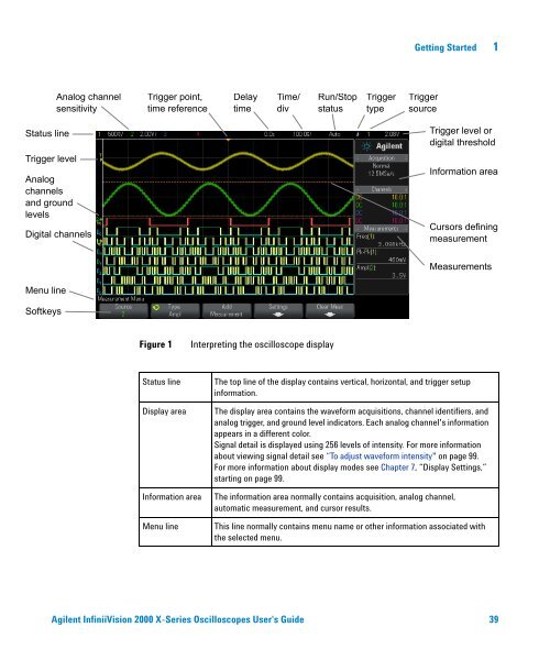
- Page 40 and 41: 1 Getting StartedSoftkey labelsThes
- Page 42 and 43: 1 Getting Started42 Agilent Infinii
- Page 44 and 45: 2 Horizontal ControlsTriggerpointTi
- Page 46 and 47: 2 Horizontal Controlsstopped, adjus
- Page 48 and 49: 2 Horizontal ControlsXY Time ModeTh
- Page 50 and 51: 2 Horizontal ControlsNOTEZ-Axis Inp
- Page 52 and 53: 2 Horizontal ControlsNegative delay
- Page 54 and 55: 2 Horizontal Controls3 Press Play M
- Page 56 and 57: 3 Vertical ControlsChannel,Volts/di
- Page 58 and 59: 3 Vertical ControlsTIPIf the channe
- Page 60 and 61: 3 Vertical ControlsThe Probe Check
- Page 64 and 65: 4 Math Waveforms2 If f(t) is not al
- Page 66 and 67: 4 Math WaveformsFigure 5 Example of
- Page 69: Math Waveforms 4• Center — sets
- Page 72 and 73: 4 Math WaveformsFFT UnitsFFT DC Val
- Page 74 and 75: 4 Math WaveformsFFT Spectral Leakag
- Page 76 and 77: 5 Reference Waveforms2 In the Refer
- Page 78 and 79: 5 Reference Waveforms1 Display the
- Page 80 and 81: 6 Digital ChannelsTurning off power
- Page 82 and 83: 6 Digital Channels6 For high- speed
- Page 84 and 85: 6 Digital ChannelsAny digital chann
- Page 86 and 87: 6 Digital ChannelsThe sizing contro
- Page 88 and 89:
6 Digital ChannelsTo display digita
- Page 90 and 91:
6 Digital ChannelsX1 cursorX2 curso
- Page 92 and 93:
6 Digital ChannelsInput ImpedanceTh
- Page 94 and 95:
6 Digital Channels100 kImpedance10
- Page 96 and 97:
6 Digital Channelsyou will discover
- Page 98 and 99:
6 Digital Channels98 Agilent Infini
- Page 102 and 103:
7 Display Settings3 To erase the re
- Page 105 and 106:
Agilent InfiniiVision 2000 X-Series
- Page 107:
Labels 8The figure above shows the
- Page 110 and 111:
8 Labels110 Agilent InfiniiVision 2
- Page 112 and 113:
9 TriggersYou can save trigger setu
- Page 114 and 115:
9 Triggers• Analog channel, 1 to
- Page 116 and 117:
9 TriggersPattern TriggerThe Patter
- Page 118 and 119:
9 TriggersNOTESpecifying an Edge in
- Page 120 and 121:
9 Triggers• For digital channels,
- Page 122:
9 TriggersNOTEIt is important, when
- Page 128:
9 TriggersFigure 18Triggering on Al
- Page 131 and 132:
Agilent InfiniiVision 2000 X-Series
- Page 133 and 134:
Trigger Mode/Coupling 10Trigger Ind
- Page 135 and 136:
Trigger Mode/Coupling 10Note that T
- Page 137 and 138:
Trigger Mode/Coupling 10CAUTIONMaxi
- Page 139 and 140:
Agilent InfiniiVision 2000 X-Series
- Page 141 and 142:
Acquisition Control 11Overview of S
- Page 144 and 145:
11 Acquisition ControlOscilloscope
- Page 146 and 147:
11 Acquisition Control• Normal
- Page 149 and 150:
Acquisition Control 11Use the horiz
- Page 151:
Acquisition Control 11See Also •
- Page 154 and 155:
11 Acquisition ControlSegmented Mem
- Page 156 and 157:
12 CursorsY CursorsY cursors are ho
- Page 158 and 159:
12 CursorsThe currently selected cu
- Page 160 and 161:
12 CursorsFigure 30Cursors track Zo
- Page 162 and 163:
12 CursorsFigure 32Moving the curso
- Page 164 and 165:
13 MeasurementsTo make automatic me
- Page 166 and 167:
13 MeasurementsMeasurementValidforM
- Page 168 and 169:
13 MeasurementsPeak-PeakMaximumMini
- Page 170 and 171:
13 MeasurementsBaseOvershootThe Bas
- Page 172 and 173:
13 Measurementslocal MaximumPreshoo
- Page 174 and 175:
13 Measurements-3σ -2σ -1σ 1σ
- Page 176 and 177:
13 MeasurementsFrequencyFrequency i
- Page 178 and 179:
13 MeasurementsRise TimeFall TimeDe
- Page 180 and 181:
13 Measurements1 Press the [Meas] k
- Page 182 and 183:
13 MeasurementsIncreasing the lower
- Page 184 and 185:
14 Mask Testing5 Press Automask.6 I
- Page 186 and 187:
14 Mask TestingRun UntilThe Run Unt
- Page 188 and 189:
14 Mask TestingMask StatisticsFrom
- Page 190 and 191:
14 Mask Testing• Oscilloscope Set
- Page 192 and 193:
14 Mask TestingThe mask scaling con
- Page 194 and 195:
14 Mask Testing:CHAN1:RANG +4.00E+0
- Page 196 and 197:
15 Waveform GeneratorThe waveform g
- Page 198 and 199:
15 Waveform GeneratorNotice that yo
- Page 200 and 201:
15 Waveform GeneratorSoftkey (logic
- Page 202 and 203:
16 Save/Recall (Setups, Screens, Da
- Page 204 and 205:
16 Save/Recall (Setups, Screens, Da
- Page 206 and 207:
16 Save/Recall (Setups, Screens, Da
- Page 208 and 209:
16 Save/Recall (Setups, Screens, Da
- Page 210 and 211:
16 Save/Recall (Setups, Screens, Da
- Page 212 and 213:
16 Save/Recall (Setups, Screens, Da
- Page 214 and 215:
16 Save/Recall (Setups, Screens, Da
- Page 216 and 217:
17 Print (Screens)4 Press the Optio
- Page 218 and 219:
17 Print (Screens)• Invert Gratic
- Page 220 and 221:
18 Utility SettingsSee Also• LAN
- Page 222 and 223:
18 Utility SettingsIf Automatic is
- Page 224 and 225:
18 Utility SettingsUSB StorageDevic
- Page 226 and 227:
18 Utility SettingsIf the ground le
- Page 228 and 229:
18 Utility Settings• Preserve —
- Page 230 and 231:
18 Utility Settings• “To check
- Page 232 and 233:
18 Utility Settings4 Connect a BNC
- Page 234 and 235:
18 Utility Settings1 Write the foll
- Page 236 and 237:
18 Utility Settings236 Agilent Infi
- Page 238 and 239:
19 Web InterfaceThe web interface f
- Page 240 and 241:
19 Web InterfaceThe SCPI Command wi
- Page 242 and 243:
19 Web InterfaceRemote Programming
- Page 244 and 245:
19 Web InterfaceYou can click Previ
- Page 246 and 247:
19 Web InterfaceIdentification Func
- Page 248 and 249:
19 Web InterfaceTo set a password:1
- Page 250 and 251:
19 Web Interface250 Agilent Infinii
- Page 252 and 253:
20 Reference• “Transient Withst
- Page 254 and 255:
20 ReferenceProbes and AccessoriesS
- Page 256 and 257:
20 ReferenceTable 8Model1146AN2774A
- Page 258 and 259:
20 ReferenceOther Options Available
- Page 260 and 261:
20 ReferenceBinary Header FormatFil
- Page 262 and 263:
20 ReferenceWaveform DataHeaderA wa
- Page 264 and 265:
20 ReferenceFile Header12 bytesNumb
- Page 266 and 267:
20 ReferenceCSV and ASCII XY file s
- Page 268 and 269:
20 Reference268 Agilent InfiniiVisi
- Page 270 and 271:
IndexCursors key, 33Cursors knob, 3
- Page 272 and 273:
IndexMulticast DNS, 221Multiply mat
- Page 274:
Indexunits, external trigger probe,