
You also want an ePaper? Increase the reach of your titles
YUMPU automatically turns print PDFs into web optimized ePapers that Google loves.
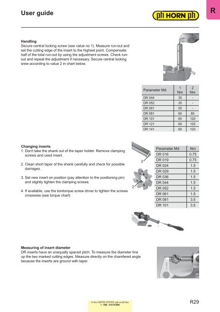
User guideRHandlingSecure central locking screw (see value no 1). Measure run-out andset the cutting edge of the insert to the highest point. Compensatehalf of the total run-out by using the adjustment screws. Check runoutand repeat the adjustment if necessary. Secure central lockingsrew according to value 2 in chart below.Parameter Md1Nm2Nm<strong>DR</strong> 044 35 -<strong>DR</strong> 052 35 -<strong>DR</strong> 061 55 -<strong>DR</strong> 081 60 85<strong>DR</strong> 101 60 120<strong>DR</strong> 121 60 120<strong>DR</strong> 141 60 120Changing inserts1. Don't take the shank out of the taper holder. Remove clampingscrews and used insert.2. Clean short taper of the shank carefully and check for possibledamages.3. Set new insert on position (pay attention to the positioning pin)and slightly tighten the clamping screws.4. If available, use the torxtorque screw driver to tighten the screwscrosswise (see torque chart)22Parameter Md Nm<strong>DR</strong> 016 0.75<strong>DR</strong> 019 0.75<strong>DR</strong> 024 1.5<strong>DR</strong> 029 1.5<strong>DR</strong> 036 1.5<strong>DR</strong> 044 1.5<strong>DR</strong> 052 1.5<strong>DR</strong> 061 1.5<strong>DR</strong> 081 3.5<strong>DR</strong> 101 3.5Measuring of insert diameter<strong>DR</strong> inserts have an unequally spaced pitch. To measure the diameter lineup the two marked cutting edges. Measure directly on the chamfered anglebecause the inserts are ground with taper.In the UNITED STATES call us toll free1 - 888 - 818 <strong>HORN</strong>R29