KR C2 sr - KUKA Robotics
KR C2 sr - KUKA Robotics
KR C2 sr - KUKA Robotics

Create successful ePaper yourself
Turn your PDF publications into a flip-book with our unique Google optimized e-Paper software.
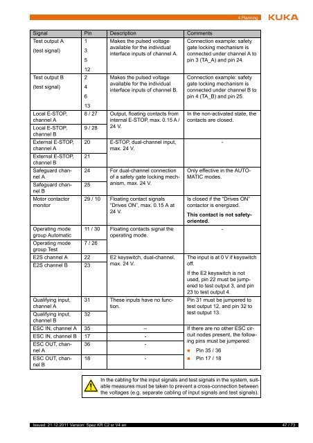
4 PlanningSignal Pin Description CommentsTest output A(test signal)Test output B(test signal)Local E-STOP,channel ALocal E-STOP,channel BExternal E-STOP,channel AExternal E-STOP,channel BSafeguard channelASafeguard channelBMotor contactormonitorOperating modegroup AutomaticOperating modegroup Test1351224613Makes the pulsed voltageavailable for the individualinterface inputs of channel A.Makes the pulsed voltageavailable for the individualinterface inputs of channel B.8 / 27 Output, floating contacts frominternal E-STOP, max. 0.15 A /9 / 28 24 V.20 E-STOP, dual-channel input,max. 24 V.2124 For dual-channel connectionof a safety gate locking mechanism,max. 24 25V.29 / 10 Floating contact signals“Drives ON”, max. 0.15 A at24 V.11 / 30 Floating contacts signal theoperating mode.7 / 26E2S channel A 22 E2 keyswitch, dual-channel,E2S channel B 23 max. 24 V.Qualifying input,channel AQualifying input,channel B31 These inputs have no function.32Connection example: safetygate locking mechanism isconnected under channel A topin 3 (TA_A) and pin 24.Connection example: safetygate locking mechanism isconnected under channel B topin 4 (TA_B) and pin 25.In the non-activated state, thecontacts are closed.Only effective in the AUTO-MATIC modes.Is closed if the “Drives ON”contactor is energized.This contact is not safetyoriented.The input is at 0 V if keyswitchoff.If the E2 keyswitch is notused, pin 22 must be jumperedto test output 3, and pin23 to test output 4.Pin 31 must be jumpered totest output 12, and pin 32 totest output 13.ESC IN, channel A 35 -- If there are no other ESC circuitnodes present, the follow-ESC IN, channel B 17 -ing pins must be jumpered:ESC OUT, channel36 -A• Pin 35 / 36ESC OUT, channelB18 -• Pin 17 / 18--In the cabling for the input signals and test signals in the system, suitablemeasures must be taken to prevent a cross-connection betweenthe voltages (e.g. separate cabling of input signals and test signals).Issued: 21.12.2011 Version: Spez <strong>KR</strong> <strong>C2</strong> <strong>sr</strong> V4 en47 / 73