Download file - Ayuntamiento de Zaragoza
Download file - Ayuntamiento de Zaragoza
Download file - Ayuntamiento de Zaragoza

Create successful ePaper yourself
Turn your PDF publications into a flip-book with our unique Google optimized e-Paper software.
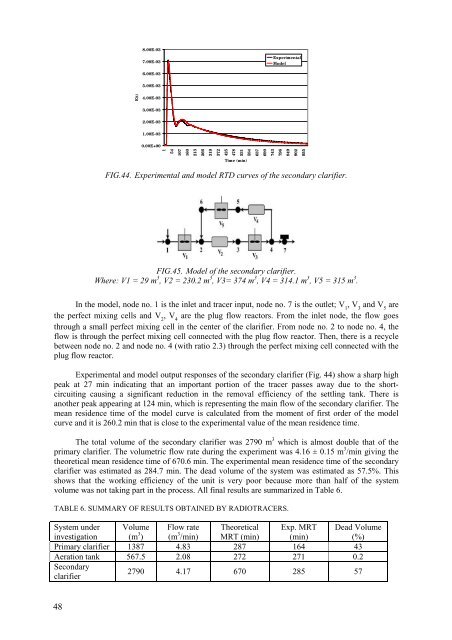
8.00E-037.00E-03ExperimentalMo<strong>de</strong>l6.00E-035.00E-034.00E-033.00E-032.00E-031.00E-030.00E+00154107160213266319372E(t)425478531584637690743796849902955Time (min)FIG.44. Experimental and mo<strong>de</strong>l RTD curves of the secondary clarifier.FIG.45. Mo<strong>de</strong>l of the secondary clarifier.Where: V1 = 29 m 3 , V2 = 230.2 m 3 , V3= 374 m 3 , V4 = 314.1 m 3 , V5 = 315 m 3 .In the mo<strong>de</strong>l, no<strong>de</strong> no. 1 is the inlet and tracer input, no<strong>de</strong> no. 7 is the outlet; V 1, V 3and V 5arethe perfect mixing cells and V 2, V 4are the plug flow reactors. From the inlet no<strong>de</strong>, the flow goesthrough a small perfect mixing cell in the center of the clarifier. From no<strong>de</strong> no. 2 to no<strong>de</strong> no. 4, theflow is through the perfect mixing cell connected with the plug flow reactor. Then, there is a recyclebetween no<strong>de</strong> no. 2 and no<strong>de</strong> no. 4 (with ratio 2.3) through the perfect mixing cell connected with theplug flow reactor.Experimental and mo<strong>de</strong>l output responses of the secondary clarifier (Fig. 44) show a sharp highpeak at 27 min indicating that an important portion of the tracer passes away due to the shortcircuitingcausing a significant reduction in the removal efficiency of the settling tank. There isanother peak appearing at 124 min, which is representing the main flow of the secondary clarifier. Themean resi<strong>de</strong>nce time of the mo<strong>de</strong>l curve is calculated from the moment of first or<strong>de</strong>r of the mo<strong>de</strong>lcurve and it is 260.2 min that is close to the experimental value of the mean resi<strong>de</strong>nce time.The total volume of the secondary clarifier was 2790 m 3 which is almost double that of theprimary clarifier. The volumetric flow rate during the experiment was 4.16 ± 0.15 m 3 /min giving thetheoretical mean resi<strong>de</strong>nce time of 670.6 min. The experimental mean resi<strong>de</strong>nce time of the secondaryclarifier was estimated as 284.7 min. The <strong>de</strong>ad volume of the system was estimated as 57.5%. Thisshows that the working efficiency of the unit is very poor because more than half of the systemvolume was not taking part in the process. All final results are summarized in Table 6.TABLE 6. SUMMARY OF RESULTS OBTAINED BY RADIOTRACERS.System un<strong>de</strong>rinvestigationVolume(m 3 )Flow rate(m 3 /min)TheoreticalMRT (min)Exp. MRT(min)Primary clarifier 1387 4.83 287 164 43Aeration tank 567.5 2.08 272 271 0.2SecondaryclarifierDead Volume(%)2790 4.17 670 285 5748