Download file - Ayuntamiento de Zaragoza
Download file - Ayuntamiento de Zaragoza
Download file - Ayuntamiento de Zaragoza

Create successful ePaper yourself
Turn your PDF publications into a flip-book with our unique Google optimized e-Paper software.
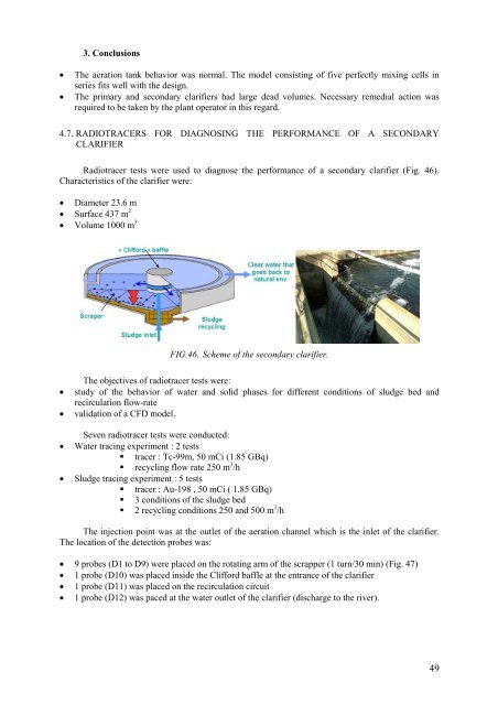
3. Conclusions• The aeration tank behavior was normal. The mo<strong>de</strong>l consisting of five perfectly mixing cells inseries fits well with the <strong>de</strong>sign.• The primary and secondary clarifiers had large <strong>de</strong>ad volumes. Necessary remedial action wasrequired to be taken by the plant operator in this regard.4.7. RADIOTRACERS FOR DIAGNOSING THE PERFORMANCE OF A SECONDARYCLARIFIERRadiotracer tests were used to diagnose the performance of a secondary clarifier (Fig. 46).Characteristics of the clarifier were:• Diameter 23.6 m• Surface 437 m 2• Volume 1000 m 3 FIG.46. Scheme of the secondary clarifier.The objectives of radiotracer tests were:• study of the behavior of water and solid phases for different conditions of sludge bed andrecirculation flow-rate• validation of a CFD mo<strong>de</strong>l.Seven radiotracer tests were conducted:• Water tracing experiment : 2 tests• tracer : Tc-99m, 50 mCi (1.85 GBq)• recycling flow rate 250 m 3 /h• Sludge tracing experiment : 5 tests• tracer : Au-198 , 50 mCi ( 1.85 GBq)• 3 conditions of the sludge bed• 2 recycling conditions 250 and 500 m 3 /hThe injection point was at the outlet of the aeration channel which is the inlet of the clarifier.The location of the <strong>de</strong>tection probes was:• 9 probes (D1 to D9) were placed on the rotating arm of the scrapper (1 turn/30 min) (Fig. 47)• 1 probe (D10) was placed insi<strong>de</strong> the Clifford baffle at the entrance of the clarifier• 1 probe (D11) was placed on the recirculation circuit• 1 probe (D12) was paced at the water outlet of the clarifier (discharge to the river).49