Source Zone Delineation Demonstration Report - Triad Resource ...
Source Zone Delineation Demonstration Report - Triad Resource ...
Source Zone Delineation Demonstration Report - Triad Resource ...

You also want an ePaper? Increase the reach of your titles
YUMPU automatically turns print PDFs into web optimized ePapers that Google loves.
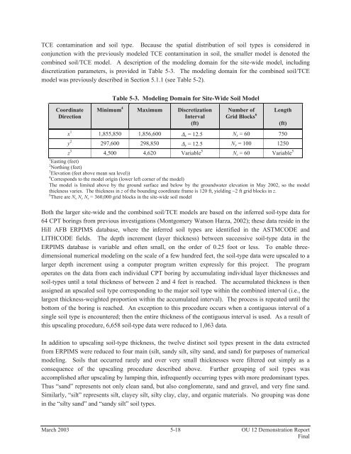
TCE contamination and soil type. Because the spatial distribution of soil types is considered inconjunction with the previously modeled TCE contamination in soil, the smaller model is denoted thecombined soil/TCE model. A description of the modeling domain for the site-wide model, includingdiscretization parameters, is provided in Table 5-3. The modeling domain for the combined soil/TCEmodel was previously described in Section 5.1.1 (see Table 5-2).Table 5-3. Modeling Domain for Site-Wide Soil ModelCoordinateDirectionMinimum 4 Maximum DiscretizationInterval(ft)Number ofGrid Blocks 6Length(ft)x 1 1,855,850 1,856,600 Δ x = 12.5 N x = 60 750y 2 297,600 298,850 Δ y = 12.5 N y = 100 1250z 3 4,500 4,620 Variable 5 N z = 60 Variable 51 Easting (feet)2 Northing (feet)3 Elevation (feet above mean sea level))4 Corresponds to the model origin (lower left corner of the model)The model is limited above by the ground surface and below by the groundwater elevation in May 2002, so the modelthickness varies. The thickness in z of the bounding coordinate frame is 120 ft, yielding ~2 ft grid blocks in z.6 There are N x N y N z = 360,000 grid blocks in the site-wide soil modelBoth the larger site-wide and the combined soil/TCE models are based on the inferred soil-type data for64 CPT borings from previous investigations (Montgomery Watson Harza, 2002); these data reside in theHill AFB ERPIMS database, where the inferred soil types are identified in the ASTMCODE andLITHCODE fields. The depth increment (layer thickness) between successive soil-type data in theERPIMS database is variable and often small, on the order of 0.25 foot or less. To enable threedimensionalnumerical modeling on the scale of a few hundred feet, the soil-type data were upscaled to alarger depth increment using a computer program written expressly for this project. The programoperates on the data from each individual CPT boring by accumulating individual layer thicknesses andsoil-types until a total thickness of between 2 and 4 feet is reached. The accumulated thickness is thenassigned an upscaled soil type corresponding to the major soil type within the combined interval (i.e., thelargest thickness-weighted proportion within the accumulated interval). The process is repeated until thebottom of the boring is reached. An exception to this procedure occurs when a contiguous interval of asingle soil type is encountered; then the entire thickness of the contiguous interval is used. As a result ofthis upscaling procedure, 6,658 soil-type data were reduced to 1,063 data.In addition to upscaling soil-type thickness, the twelve distinct soil types present in the data extractedfrom ERPIMS were reduced to four main (silt, sandy silt, silty sand, and sand) for purposes of numericalmodeling. Soils that occurred rarely and over very small thicknesses were filtered out simply as aconsequence of the upscaling procedure described above. Further grouping of soil types wasaccomplished after upscaling by lumping thin, infrequently occurring types with more predominant types.Thus “sand” represents not only clean sand, but also conglomerate, sand and gravel, and very fine sand.Similarly, “silt” represents silt, clayey silt, silty clay, clay, and organic materials. No grouping was donein the “silty sand” and “sandy silt” soil types.March 2003 5-18 OU 12 <strong>Demonstration</strong> <strong>Report</strong>Final