UL Addendum - Tyco Security Products
UL Addendum - Tyco Security Products
UL Addendum - Tyco Security Products

You also want an ePaper? Increase the reach of your titles
YUMPU automatically turns print PDFs into web optimized ePapers that Google loves.
C•CURE 800/8000 System and ComponentsVersion 9.4<strong>UL</strong> <strong>Addendum</strong>Software House70 Westview StreetLexington, MA 02421Fax: 781-466-9550 Phone: 781-466-6660C·CURE 800/8000 V9.4 <strong>UL</strong> <strong>Addendum</strong>i
C•CURE® and Software House® are registered trademarks of <strong>Tyco</strong> International Ltd. and its RespectiveCompanies.Certain Product names mentioned herein may be trade names and/or registered trademarks of other companies.Information about other products furnished by Software House is believed to be accurate. However, noresponsibility is assumed by Software House for the use of these products, or for an infringement of rights of theother companies that may result from their use.C•CURE 800/8000 Version: 9.4UM-029-L-<strong>UL</strong> REV L0Release Date: August 2008This manual is proprietary information of Software House. Unauthorized reproduction of any portion of this manualis prohibited. The material in this manual is for informational purposes only. It is subject to change without notice.Software House assumes no responsibility for incorrect information this manual may contain.© Copyright 2005-2008 by <strong>Tyco</strong> International Ltd. and its Respective Companies.All rights reserved.iiC·CURE 800/8000 V9.4 <strong>UL</strong> <strong>Addendum</strong>
OVERVIEWThis addendum provides <strong>UL</strong> recommendations, requirements, and operational restrictions forC•CURE 800/8000 system components.GENERAL REQUIREMENTS<strong>UL</strong> approved installations must conform to the following general requirements:• The System must be installed within the protected premise in accordance with the NationalElectrical Code (NFPA70) and the local authorities having jurisdiction.• All interconnecting devices must be <strong>UL</strong> Listed and, if applicable, powered by <strong>UL</strong> Listedaccess control or burglar alarm power-limited power supplies capable of 24 hours of standbypower.• All cabling and wiring must be suitable for the functionality for which they are being usedand <strong>UL</strong> Listed and/or Recognized.• Unless otherwise noted, all external connections used (relays, battery wires, power supplywires, etc.) must be connected to power limited circuits only.System component, functions, and features not specifically included in this addendum areuntested or do not conform to <strong>UL</strong> requirements.HARDWARE CONFIGURATION REQUIREMENTSSupply Line Transient ProtectionAll supply lines must be protected by a transient protection device that complies with theStandard for Transient Voltage Surge Suppressors, <strong>UL</strong> 1449, with a maximum marked rating of330V. This includes the AC power lines for all C•CURE 800/8000 equipment such as client andserver computers; network hubs, routers, and bridges; terminal servers; leased-line modems; andprotocol converters. Excluded from this requirement are apC/L and apC/8X panels and iSTARcontrollers and their periphery equipment like RMs and I/8 boards.Signal Line Transient ProtectionShall comply with the standard for protectors for data communications and fire alarm circuits<strong>UL</strong>497B, with a marked rating of 50 volts.Signal line transient protection devices are not required for readers or input devices connected toan apC/L, apC/8X panel, RM reader module, I/8board, or I/32 board.Communication Circuits and Network ComponentsAll communication circuits and network components connected to the telecommunicationsnetwork must be protected by a transient protection device that complies with the Standard forC·CURE 800/8000 V9.4 <strong>UL</strong> <strong>Addendum</strong>1
Secondary Protectors for Data Communication Circuits, <strong>UL</strong> 497A. These protectors shall beused only on the protected side of the telecommunications network. This includes the TCP/IPnetwork and serial data lines for all C•CURE 800/8000 equipment such as client and servercomputers network ports and server serial ports. Excluded from this requirement are the datalines that feed directly in to apC/L and apC/8X panels and iSTAR controllers.Temperature Controlled EnvironmentThe C•CURE 800/8000 server computer must be installed in a temperature-controlledenvironment that is maintained by the HVAC system to be in the range of 13-35°C (55-95°F).The HVAC system must be provided with at least 24 hours of standby power supplied by anengine-driven generator or standby battery. Excluded from this requirement are apC/L andapC/8X panels and iSTAR controllers and their periphery equipment like RMs and I/8 boards.Backup SystemThe C•CURE 800/8000 server computer must be completely duplicated with provision forswitchover to the backup system within 30 seconds. The backup system may be provided by asecond computer that meets C•CURE 800/8000 <strong>UL</strong> 1076 Listing requirements or by using afault tolerant computer. If a fault tolerant computer is used, every component, including thesoftware and the power supply, must be duplicated.Uninterruptible Power Supply (UPS)In addition to the standby power required for the HVAC system, all system components must beprovided with UPS with sufficient capacity to operate the equipment for a minimum of 15minutes. If more than 15 minutes is required for HVAC standby power to come on-line andstabilize, the UPS must be capable of providing input for at least that amount of time. When theUPS is installed, there must be a means for disconnecting the input to the UPS while maintainingcontinuity of power to the system components so that maintenance and repair can be performed.All UPS devices must comply with the Standard for Uninterruptible Power Supply Equipment,<strong>UL</strong> 1778, or the Standard for Fire Protective Signaling Devices, <strong>UL</strong> 1481.2 C·CURE 800/8000 V9.4 <strong>UL</strong> <strong>Addendum</strong>
SOFTWARE CONFIGURATION REQUIREMENTSMonitoring Station PollingThe Monitoring Station polls the server to ensure that the server and communications circuit isoperational. The polling frequency is user-configurable and can be changed through DiagSystemby modifying the Monitoring Station system variable, “NetworkPollingInterval.” The intervalbetween polls must not exceed 90seconds.Dial-up Communication Circuit ConfigurationThe C•CURE 800/8000 supports the configuration of dial-up communication circuits betweenthe server and apCs.Note: This configuration must not be used in a <strong>UL</strong> 1076 system.Cabinet Tamper Detection InputsThe C•CURE 800/8000 supports inputs that detect cabinet tamper for apCs, iSTARs, and RMs.All apCs, iSTARs, and RMs must be configured to detect cabinet tamper. Each tamper inputmust specify that an event be triggered when the device is tampered. This event must beconfigured to always be armed, on-line, annunciated, and require acknowledgement.AC Power Fail Inputs for apCs and iSTARsThe C•CURE 800/8000 supports inputs that detect AC power fail for apCs and iSTARs. AllapCs and iSTARs must be configured to detect AC power fail. Each AC power fail input mustspecify that an event be triggered when the apC or iSTAR loses AC power. This event must beconfigured to always be armed, on-line, annunciated, and require acknowledgement.Event Association with apC, iSTAR, and RM Communications FailureThe C•CURE 800/8000 supports the association of events with apC, iSTAR, and RMcommunications failure. Each apC, iSTAR, and RM must be configured to trigger an event whenthe device goes into communications failure. This event must be configured to always be armed,on-line, annunciated, and require acknowledgement.Supervised Inputs on apCs, iSTARs and I/8 - I/32 BoardsThe C•CURE 800/8000 supports supervised inputs located on apCs, iSTARs, and I8/I32 boards.Each supervised input must be configured to trigger an event when the input is activated and asupervision error is detected for the input. These events must be configured to always be armed,on-line, annunciated, and require acknowledgement.C·CURE 800/8000 V9.4 <strong>UL</strong> <strong>Addendum</strong>3
Assignment of Priorities to EventsThe C•CURE 800/8000 supports assigning priorities to events. If this feature is used, the order ofpriority must be as follows — from highest to lowest:1. Fire alarm and industrial supervision where a risk of injury to person or damage ordestruction of property may be involved2. Hold-up (Robbery) or panic alarm3. Burglar alarm4. Watchman tour5. Fire alarm supervision error6. Burglar alarm supervision error7. Industrial supervision where a risk of injury to person or damage or destruction of propertywill not be involved8. Other supervisory servicesNote: Items 2 and 3 may have equal priority; items 5 and 6 may have equal priority; and items 7and 8 may have equal priority.4 C·CURE 800/8000 V9.4 <strong>UL</strong> <strong>Addendum</strong>
MINIMUM PC CONFIGURATION FOR C•CURE 800/8000VERSION 9.XAll computers used in the C•CURE System must be <strong>UL</strong> Listed.Installation Disk Space Requirements for the ServerTable 1. Server Installation Space RequirementsInstallation TypeInstallation (new/update) without EnhancedReportingAdditional requirements for update installationwithout Enhanced ReportingMinimum Free Disk Space2 GB total (300MB on System Drive + remainderanywhere)2X the size of the current CF databaseInstallation (new/update) with Enhanced Reporting 3 GB total (300MB on System Drive + remainderanywhere)Additional requirements for update installation with 2X the size of the current CF database + 2X theEnhanced Reportingcombined size of all actively used Journal databasesNote: If iSTAR Fast Personnel Download is used, disk space should be allocated on the hostServer. A set of files is created for each individual iSTAR controller, up to 64 MB in size if thecontroller is full.Server Hardware Required• Minimum CPU speed requirements are based on Pentium processors.• A dedicated parallel or USB port is required for the Sentinel.Note: In the following charts, the number of cardholders and the minimum RAM and CPUspeed columns represent the “tested” minimums and are not necessarily the recommendedvalues. More RAM and a CPU faster than stated in the chart will generally allow morecardholders and better system performance.For optimum performance, Software House recommends 1 GB of RAM for Models 40 andhigher.Note: System performance will vary depending upon the specific hardware configuration,including the number of communication lines/ports, download/upload frequency, number ofcards per person, etc.C·CURE 800/8000 V9.4 <strong>UL</strong> <strong>Addendum</strong>5
Table 2. Server Requirements – One Access Card Per PersonC•CURE 800/8000 Without the Enhanced Reporting OptionServer Model SimultaneousClientsCardReadersInputs Outputs CardHoldersMin. RAMMin. CPUSpeedCC800-1
Table 4. Server Requirements – Five Access Cards Per PersonC•CURE 800/8000 Without the Enhanced Reporting OptionServer Model SimultaneousClientsCardReadersInputs Outputs CardHoldersMin. RAMMin. CPUSpeedCC800-1
EMC AutoStart/Replistor RequirementsSystems with AutoStart/Replistor must be:• Intel based systems that are on the Microsoft hardware Availability List (HCL).• Windows Server 2003 Server, Enterprise server, or Data Center Server• Fixed IP for all agent nodes• CPU speed = 1.5 GHz minimum• RAM = 1 GB minimumServers that employ EMC AutoStart mirroring (HA) are required to be triple-homed (3 NICs)and be within 10 km of each other.8 C·CURE 800/8000 V9.4 <strong>UL</strong> <strong>Addendum</strong>
INSTALLATION LOCATIONSThe following table shows indoor/outdoor approval for system components.Note: This system must be installed within the protected premise in accordance with theNational Electrical Code (NFPA70), and the local authorities having jurisdiction.Table 6. System Component Indoor/Outdoor Approval *ProductapC/8X Access Control PanelapC/L Access Control PaneliSTAR Access Control PanelWyreless Panel Interface ModuleWyreless Access Point ModuleReaders: RM1-MP, RM2-MPReaders: RM2L-MPReaders: RM3-MPReaders: RM1-PI, RM2-PReaders: RM2L-PIReaders: RM1-PH, RM2-PHReaders: RM2L-PHReaders: RM3-PHReaders: RM1-WOutdoor usepermittedNoNoNoNoNoNoNoNoNoNoNoNoNoNo• Optional heater kit (p/n 130-915 for 115VAC, p/n 130-915A for 220V) should be used if thetemperature is expected to drop below 40 o F.Note: The optional heater kit (p/n 130-915A for 220V) has not been evaluated by <strong>UL</strong>:Maximum operating conditions and power requirements are shown in Table 7 on the next page.C·CURE 800/8000 V9.4 <strong>UL</strong> <strong>Addendum</strong>9
Table 7. Operating Conditions and Power RequirementsModelOperatingTemperature(Environmental)OperatingTemperature withHeater KitPowerRequirementsDimensionsMagnetic Stripe:RM1-MP,RM2-MP32° F to 140° F0° C to 60° C-22° F to 140° F-30° C to 60° C+12V DC80 mA5.10 x 5.60 x 1.95 in. (12.95x 14.22 x 4.95 cm)21 oz. (588 g)Magnetic Stripe withLCD Display:RM2L-MP32° F to 140° F0° C to 60° C95% humidity NoncondensingNot applicable+12V DC180 mA5.10 x 5.60 x 1.95 in. (12.95x 14.22 x 4.95 cm)23 oz. (644 g)Magnetic StripeMullion:RM3-MP32° F to 140° F0° C to 60° C-22° F to 140° F-30° C to 60° C+12V DC80 mA5.10 x 1.91 x 1.81 in. (12.95x 4.85 x 4.60 cm)10 oz. (280 g)Indala Proximity:RM1-PI,RM2-PI32° F to 140° F0° C to 60° C-22° F to 140° F-30° C to 60° C+12V DC80 mA5.10 x 5.60 x 1.95 in. (12.95x 14.22 x 4.95 cm)25 oz. (700 g)Indala Proximity withLCD Display:RM2L-PI32° F to 140° F0° C to 60° C95% humidity NoncondensingNot applicable+12V DC180 mA5.10 x 5.60 x 1.95 in. (12.95x 14.22 x 4.95 cm)27 oz. (756 g)Hughes ProximityRM1-PH,RM2-PH32° F to 140° F0° C to 60° C-22° F to 140° F-30° C to 60° C+12V DC135 mA average250 mA peak5.10 x 5.60 x 1.95 in. (12.95x 14.22 x 4.95 cm)21 oz. (588 g)Hughes Proximitywith LCD Display:RM2L-PH32° F to 140° F0° C to 60° C95% humidity NoncondensingNot applicable+12V DC135 mA average250 mA peak5.10 x 5.60 x 1.95 in. (12.95x 14.22 x 4.95 cm)23 oz. (644 g)Hughes ProximityMullion:RM3-PH-22° F to 149° F-30° C to 65° CNot applicable+12V DC135 mA average250 mA peak5.10 x 1.91 x 1.81 in. (12.95x 4.85 x 4.60 cm)10 oz. (280 g)Wiegand:RM1-W ,RM2-W32° F to 140° F0° C to 60° C-32° F to 140° F0° C to 60° C+12V DC180 mA5.10 x 5.60 x 1.95 in. (12.95x 14.22 x 4.95 cm)25 oz. (700 g)10 C·CURE 800/8000 V9.4 <strong>UL</strong> <strong>Addendum</strong>
ModelOperatingTemperature(Environmental)OperatingTemperature withHeater KitPowerRequirementsDimensionsWiegand with LCDDisplay:RM2L-W32° F to 140° F0° C to 60° C95% humidity NoncondensingNot applicable+12V DC180 mA5.10 x 5.60 x 1.95 in. (12.95x 14.22 x 4.95 cm)25 oz. (700 g)Wiegand withMullion:RM3-W-40° F to 158° F-40° C to 70° CNot applicable+12V DC80 mA5.10 x 1.91 x 1.81 in. (12.95x 14.22 x 4.95 cm)13 oz. (364 g)C·CURE 800/8000 V9.4 <strong>UL</strong> <strong>Addendum</strong>11
OPERATIONAL REQUIREMENTSOperation/Testing1. Readers are tested by reading a sample card and observing the results on the MonitoringStation application. If the reader and card formats are properly set, an “access granted” or“access denied” message appears on the screen. A “card misread” message indicates that thereader is not properly installed or the card format does not match the settings in the C•CURE800/8000 Administration application.2. Inputs are tested by opening/closing (activating/deactivating) the device. Input devices musthave the proper supervision resistors installed to function with C•CURE 800/8000. Wheninputs are working properly, you see the messages “input xxx activated” and “input xxxdeactivated. Shorting or opening the cable is indicated as “input xxx open loop” or “inputxxx shorted” on the Monitoring Station application.3. Outputs are tested by performing a manual action in the Monitoring Station application. Youcan momentary open a door or activate any other relay. You can then use a resistance meterto determine if the relay contacts close and open properly.Maintenance• For electronic modules exposed to high dust environments: Check the assemblies forexcess dust build-up every 6 months and remove the dust and dirt from the assemblies withforced air.• For readers exposed to external weather conditions: Check the enclosure sealing for leaksat 6-month intervals. If the seal is not intact, replace the gasket.12 C·CURE 800/8000 V9.4 <strong>UL</strong> <strong>Addendum</strong>
OPERATIONAL RESTRICTIONSThe following conditions are not recommended, and may result in impaired operation of thesystem component.Proximity Card Readers• All Software House RM reader series products can be installed on metal surfaces. Somethird-party readers, such as HID ProxPro Plus, may exhibit reduced performance whenmounted near a metal object. Consult the installation guide or users’ manual for each specificproduct.• Performance may also degrade if the reader is exposed to any Radio Frequency fields withfrequencies near 125 KHz or 13.56 MHz.• The cable used to connect a Wiegand reader must not exceed 500 ft.Magnetic Stripe Readers• Performance may degrade or the unit stops working if installed near magnetic sources, suchas a motor.• The cable used to connect a magnetic read head must not exceed 10 ft.Note: In general, do not run reader cabling near high voltage lines or motorized equipment, suchas elevators or compressors.SUPPORTED/UNSUPPORTED FEATURESIN C•CURE 800/8000 VERSION 9.3Table 8 shows the features that were evaluated by <strong>UL</strong>.Table 8. Features Evaluated by <strong>UL</strong>FeatureEvent/Alarm MonitoringDoor ControlElevator ControlTime SpecificationsTime Zone ManagementOperator Privileges<strong>UL</strong> TestedYesYesYesYesYesYesC·CURE 800/8000 V9.4 <strong>UL</strong> <strong>Addendum</strong>13
FeatureCard Record DefinitionsCard Format DefinitionsDatabase PartitioningAutomated Personnel Data ImportAsset ManagementClearancesReportsEmergency roll call reportAudit TrailActivity MonitoringCentral System MonitoringAlarm RoutingReal Time Event PrinteriSTAR Panel SupportPaging and E-mailIntrusion Zones (iSTAR)Keypad Commands (iSTAR)Closed Circuit Television Integration (CCTV)Radionics InterfaceBi-directional Serial InterfaceGuard TourDigital Video Recording Subsystem (DVRS)Escorted Access ManagementVisitor ManagementEnhanced Door Monitoring<strong>UL</strong> TestedYesYesYesYesYesYesYesYesYesYesYesYesYesYesNoYesYesNoNoNoYesNoYesNoYes14 C·CURE 800/8000 V9.4 <strong>UL</strong> <strong>Addendum</strong>
FeatureCarpool Anti-passbackArea Muster/De-musterAdditional Holiday ListsCardholder Access EventsTemporary Personnel RecordRedundancy Qualification (AutoStart/Replistor)iSTAR Configurable Activity Buffer Size EnhancementEncryption Box QualificationSonic WallAudit Trail of <strong>Security</strong> ObjectsEvent Triggered Database Backup (on iSTAR)Enhanced PartitioningMicrosoft Windows/XP/2003 Qualification as Server PlatformManual Action ChallengeBioscrypt Biometric Enrollment in C•CURE IDiSTAR Global Anti-passbackMultiple Cards per cardholder256-bit card numbers<strong>UL</strong> TestedYesYesYesYesYesYesYesYesYesYesYesYesYesYesYesYesYesYes128 total card formats YesNetVue Presets and Patterns EnhancementEvent Sorting by Date/Time and PriorityiSTAR Reader LED and beep patternsActivation count for event enhancementActivation date/time set to date time at which cardholder is initially createdAdditional user-named fieldsYesYesYesYesNoYesC·CURE 800/8000 V9.4 <strong>UL</strong> <strong>Addendum</strong>15
FeaturePIN-only accessHolidaysLDAPRole Based ClearancesSmart CardDouble SwipeNetvue Alarm ManagementNetvue Popup Window<strong>UL</strong> TestedYesYesYesYesNoYesYesYesEMC AutoStartEMC AutoStart is required for database mirroring on LAN configurations composed of aprimary and backup server. The following shows a configuration protected by AutoStart.EMC AutoStart Server will protect and keep mission critical data and applications available bymirroring information from one server to another over a local area network (LAN). Data isupdated in real time. Should the primary server fail, the secondary server will assume control ofthe system with an exact copy of the data and application.ReplistorReplistor is recommended for WAN configurations comprised of multiple servers that requirefailover and data replication. The following shows a configuration protected by Replistor.16 C·CURE 800/8000 V9.4 <strong>UL</strong> <strong>Addendum</strong>
RepliStor replicates data from one server to another and works over a wide area network (WAN).Data can be replicated to multiple servers in remote locations. Upon a catastrophic failure of theprimary server, one of the secondary servers will be instructed to assume control to keep theapplication running and available.<strong>UL</strong> ComponentsThe following system components meet <strong>UL</strong> requirements.• Access Control Panels:• apC/8x• apC/L• iSTAR:♦ STAR008W-16: 8 Readers, 16 M memory♦ STAR008W-32: 8 Readers, 32 M memory♦ STAR008W-64: 8 Readers, 64 M memory♦ STAR016W-16: 16 Readers, 16 M memory♦ STAR016W-32: 16 Readers, 32 M memory♦ STAR016W-64: 16 Readers, 64 M memory♦ STAR008W-64A: 8 Readers, 64 M Memory♦ STAR016W-64A: 16 Readers, 64 M Memory♦ STAREX004W-64: 4 Readers, 64 M MemoryC·CURE 800/8000 V9.4 <strong>UL</strong> <strong>Addendum</strong>17
• Power Supply Backup Systems♦ apS: AS0063-00, AS0063-01.• RM Series Readers:♦ RM Series: RM1-MP, RM2-MP, RM2L-MP,RM3-MP, RM1-PI, RM1-PI, RM2-P1,RM2-PI, RM2L-PI, RM1-PH, RM2-PH, RM2L-PH, RM3-PH, RM1-W• Bioscrypt Readers:♦ V Smart-AH SCR-610• RM-DCM-2 (Rm-4E Module with enclosure)♦ Options♦ Input/Output Modules: AS0015-00, AS0074-000, AS0073-000, AS0016-00♦ Reader Expansion boards: AS0020-00, AS0020-01, AS0054-00, AS0054-01Note: Only readers included in the <strong>UL</strong> Components section can be employed in a <strong>UL</strong>-compliantsystem.The following system components have not been tested to <strong>UL</strong> requirements.• Optional communication converter: AS002• Optional dual communications converter: AS003.• Smart Card Readers: SCR series of readers.• Auxiliary relay module: ARM-1• All other readers not manufactured by Software House. (However, these readers may be <strong>UL</strong>Listed. Contact the manufacturer for details.)Note: .All interconnecting devices are to be <strong>UL</strong> Listed and, if applicable, powered only by <strong>UL</strong>Listed access control or burglar alarm power-limited power supplies capable of 24 hoursof standby power<strong>UL</strong> Replacement PartsTable 9 shows the <strong>UL</strong> Field Replaceable Units (FRU).Table 9. <strong>UL</strong> FRUProduct Code Description Field Replaceable Unit EtchAS0015-00APCS/I32, 32 SupervisedInput Module0301-0664-01 1700-0895-01AS0016-00 APC/R48 Output Rly Module 0301-0665-01 1700-0896-0118 C·CURE 800/8000 V9.4 <strong>UL</strong> <strong>Addendum</strong>
Product Code Description Field Replaceable Unit EtchAS002 RS232-485 Red. Dual Conv. AS002 1700-0899-01AS0020-00 Star Coupler 0301-0662-01 1700-0893-01AS0020-01 Mini Star Coupler 0301-0663-01 1700-0893-01AS0020-02 F-Conn Star Coupler, Coaxial 0301-0677-01 1700-0906-01AS0020-03 F-Conn Star Coupler T-Brd 0301-0678-01 1700-0907-01AS0020-04 Star Coupler F-Contr W/Trnsnbr0301-0677-010301-0678-01AS003 RS232-485 Rdnt Dual Comm AS003 1700-0900-01AS0054-00AS0054-01AS0073-000ApC Star Coupler, WiegandProxApC Star Coupler,Wiegand/ProxApC 8 Reader Input BusModule0301-0666-01 1700-0897-010301-0667-01 1700-0898-010301-0670-01 1700-0901-01AS0074-000 RM Output Final Assembly 0301-0671-01 1700-0902-01AS0063-01ApS Battery Backup w/Enclosure, Xfmr, No Bat.AS0063-03 – apS Mother BoardAS0053-000 – apS LED board1700-0903-011700-0904-01AS0063-02ApS Mother Board,Enclosure, No Bat or Xfmr.AS0063-03 – apS Mother BoardAS005-000 – apS LED board1700-0903-011700-0904-01STAR008W-16 GCM w/ 1 ACM Wiegand, 8Readers, 16M0301-0680-01 – GCM Board0301-0681-01 – Interface Board0301-0682-03 – ACM 8W Board0301-0683-01 – Relay Board0301-0684-01 – SIMM Flash Board0301-0685-01 – iSTAR LED Board0300-1380-02 – iSTAR Power SupplyAssembly1700-0908-011700-0911-011700-0912-011700-0913-011700-0914-011700-0915-01STAR008W-16 GCM w/ 2 ACM Wiegand, 160301-0680-01 – GCM BoardReaders, 16M0301-0681-01 – Interface Board0301-0682-03 – ACM 8W Board1700-0908-011700-0911-011700-0912-01C·CURE 800/8000 V9.4 <strong>UL</strong> <strong>Addendum</strong>19
Product Code Description Field Replaceable Unit Etch0301-0683-01 – Relay Board0301-0684-01 – 16 M SIMM Flash Board0301-0685-01 – iSTAR LED Board0300-1380-02 – iSTAR Power SupplyAssembly1700-0913-011700-0915-01STAR008W-32 GCM w/ 1 ACM Wiegand, 8Readers, 32M0301-0680-01 – GCM Board0301-0681-01 – Interface Board0301-0682-03 – ACM 8W Board0301-0683-01 – Relay Board0301-0684-02 – 32 M SIMM Flash Board0301-0685-01 – iSTAR LED Board0300-1380-02 – iSTAR Power SupplyAssembly1700-0908-011700-0911-011700-0912-011700-0913-011700-0915-01STAR016W-32 GCM w/ 2 ACM Wiegand, 160301-0680-01 – GCM BoardReaders, 32M0301-0681-01 – Interface Board0301-0682-03 – ACM 8W Board0301-0683-01 – Relay Board0301-0684-02 – 32 M SIMM Flash Board0301-0685-01 – iSTAR LED Board0300-1380-02 – iSTAR Power SupplyAssembly1700-0908-011700-0911-011700-0912-011700-0913-011700-0915-01STAR008W-64 GCM w/ 1 ACM Wiegand, 8Readers, 64M0301-0680-01 – GCM Board0301-0681-01 – Interface Board0301-0682-03 – ACM 8W Board0301-0683-01 – Relay Board0301-0684-03 – 64 M SIMM Flash Board0301-0685-01 – iSTAR LED Board0300-1380-02 – iSTAR Power SupplyAssembly1700-0908-011700-0911-011700-0912-011700-0913-011700-0915-01STAR016W-64 GCM w/ 2 ACM Wiegand, 160301-0680-01 – GCM BoardReaders, 64M0301-0681-01 – Interface Board0301-0682-03 – ACM 8W Board0301-0683-01 – Relay Board0301-0684-03 – 64 M SIMM Flash Board1700-0908-011700-0911-011700-0912-011700-0913-0120 C·CURE 800/8000 V9.4 <strong>UL</strong> <strong>Addendum</strong>
Product Code Description Field Replaceable Unit Etch0301-0685-01 – iSTAR LED Board0300-1380-02 – iSTAR Power SupplyAssembly1700-0915-01Reader RequirementsTable 10 describes <strong>UL</strong> supported readers, as well as the outputs and card formats for each reader.These card readers have been evaluated by <strong>UL</strong>. All other readers and card formats have not beenevaluated by <strong>UL</strong>.Table 10. <strong>UL</strong> Supported ReadersReader Output Format Card FormatRM1-MP,RM2-MPRS485Magnetic stripe, 14 charactersRM2L-MP RS485 Magnetic stripe, 14 charactersRM3-MP RS485 Magnetic stripe, 14 charactersRM1-PI RS485 Wiegand 26 or 37 bitRM2-PI RS485 Wiegand 26 or 37 bitRM2L-PIxx RS485 Wiegand 26 or 37 bitRM1-PH,RM2-PHRS485Wiegand 26 or 37 bitRM2L-PH RS485 Wiegand 26 or 37 bitRM3-PH RS485 Wiegand 26 or 37 bitElectrical RequirementsThis section describes the electrical ratings for system inputs and outputs.Table 11. Electrical ratings for inputs and outputsapC/8X Access Control PanelInput power 120 VAC, 60 Hz, 0.5ASignal InputsOutputsClass A Supervised, 0 - 14,000 ohmsDry contacts rated at 30 V AC/DC, 5.0 A non-inductiveC·CURE 800/8000 V9.4 <strong>UL</strong> <strong>Addendum</strong>21
apC/L Access Control PanelInput powerSignal InputsOutputs18 VAC, 50 VAClass A Supervised, 0 - 14,000 ohmsDry contacts rated at 30 V AC/DC, 1.0 A non-inductiveiSTAR Access Control PanelInput power 100 – 240 VAC, 2.3A @100 VAC, 1.1A @240 VAC, 47-63HzSignal InputsOutputsClass A Supervised, 0 - 14,000 ohmsDry contacts rated at 30 V AC/DC, 5.0 A non-inductiveReaders: RM1-MP, RM2-MPInput powerSignal Inputs+12V DC, +/-5%, 80mAClass A Supervised, 0 - 14,000 ohmsOutputs Open collector, +12V DC, 0.5AReaders: RM2L-MPInput powerSignal Inputs+12V DC, +/-5%, 180mAClass A Supervised, 0 - 14,000 ohmsOutputs Open collector, +12V DC, 0.5AReaders: RM3-MPInput powerSignal Inputs+12V DC, +/-5%, 80mAClass A Supervised, 0 - 14,000 ohmsOutputs Open collector, +12V DC, 0.5AReaders: RM1-PI, RM2-PIInput powerSignal Inputs+12V DC, +/-5%, 80mAClass A Supervised, 0 - 14,000 ohmsOutputs Open collector, +12V DC, 0.5AReaders: RM2L-PIInput powerSignal Inputs+12V DC, +/-5%, 180mAClass A Supervised, 0 - 14,000 ohms22 C·CURE 800/8000 V9.4 <strong>UL</strong> <strong>Addendum</strong>
Outputs Open collector, +12V DC, 0.5AReaders: RM1-PH, RM2-PHInput powerSignal Inputs+12V DC, +/-5%, 250mAClass A Supervised, 0 - 14,000 ohmsOutputs Open collector, +12V DC, 0.5AReaders: RM2L-PHInput powerSignal Inputs+12V DC, +/-5%, 250mAClass A Supervised, 0 - 14,000 ohmsOutputs Open collector, +12V DC, 0.5AReaders: RM3-PHInput powerSignal Inputs+12V DC, +/-5%, 250mAClass A Supervised, 0 - 14,000 ohmsOutputs Open collector, +12V DC, 0.5AReaders: RM1-WInput powerSignal Inputs+12V DC, +/-5%, 80mAClass A Supervised, 0 - 14,000 ohmsOutputs Open collector, +12V DC, 0.5ACabling and WireNote: All external connections (relays, battery wires, power supply wires, readers, etc.) must bemade to power limited circuits only. All cabling and wire used must be <strong>UL</strong> Listed and/orRecognized wire and must be suitable for the application, as described below.Wiring Main Power To an iSTARThe iSTAR must be connected to a power limited main circuit. Cabling must be <strong>UL</strong> Listedand/or Recognized. Refer to the product label for power requirements. The connection procedureis shown in the following diagram.1. Attach the conduit for the wiring from AC main power to the knockout closest to the powersupply in the enclosure.C·CURE 800/8000 V9.4 <strong>UL</strong> <strong>Addendum</strong>23
2. Route the wiring through the nearest conduit into the enclosure.3. Place a ferrite on the AC power cable, inside the enclosure. Use the hot wires (black orbrown) and neutral wires (blue or white) to wrap the ferrite with three wire turnings (Figure4.28).CAUTION: Ensure that you maintain 1/4" spacing between metal and exposed conductors.Strip the wiring as needed.Attach the primary earth ground wire (green or green/yellow) from the terminal to the unpaintedenclosure base PEM stud (see Figure 4.29) with a closed-loop, crimped-on connector, metal starwasherand nut. The secondary earth ground, from the power supply connector, is secured to thesame PEM stud, separated by an additional star lock washer and nut .Attach the hot wire (black or brown) to the designated screw.Attach the neutral wire (white or blue) to the designated screw.Use wire tie downs to ensure proper spacing between SELV circuits and primary wiring, andfrom chassis/metal.24 C·CURE 800/8000 V9.4 <strong>UL</strong> <strong>Addendum</strong>
Wiring Readers To an iSTARC·CURE 800/8000 V9.4 <strong>UL</strong> <strong>Addendum</strong>25
Wiring Relay OutputsThe following diagram shows typical wiring for an AC or DC door lock using the relays oneither the iSTAR panels.Note: Local DC or AC power sources must be power limited, not to exceed the electrical ratingsof the relay.26 C·CURE 800/8000 V9.4 <strong>UL</strong> <strong>Addendum</strong>
The following diagram show typical wiring for an AC or DC door lock using the RM4 andARM1 modules.Wiring the apS to an iSTARNote: Battery cables are not power limited and should be isolated from all other cabling by aminimum of ¼ inch. Route these cables away from all other wires.C·CURE 800/8000 V9.4 <strong>UL</strong> <strong>Addendum</strong>27
MONITOR POINTSDescriptionMonitor points (alarm devices connected to input circuits) are provided on the followingmodules:ModuleiSTAR ACMNumber of Inputs16 each (32 per iSTAR)I/8 Reader Bus Module 8 each (64 per iSTAR)RM-4 or RM-4E2 each (16 per iSTAR)Each monitor point functions independently and does not interfere with the operation of theothers. The hardware modules monitor the supervised inputs. Depending on the mode selectedthe following states are reported:• Normal mode - Secure, Alert, Shorted, Open, and Line Fault (NO or NC)• Single Resistor End line mode - Secure, Alert, Shorted, and Line Fault (NC only)The configuration in the host computer determines how the hardware module and the reportingsoftware will respond to the various conditions that are detected.<strong>UL</strong> Compliant SupervisionThe indication of whether a monitor point is Normally Closed (NC) or Normally Open (NO) isdone by how the resistor network is wired in conjunction with the alarm device to form asupervised End Of Line (EOL) resistor alarm zone. The host system views monitor points asbeing either logically true or false. Software House wires NO and NC supervised input circuitstwo ways because it makes the software implementation more logical.The two different methods result in an alarm loop resistance of 1K ohms being the Securesupervised state whether the monitor point is connected as a NO or NC alarm loop. Since thehardware wiring defines NO and NC, the software works with inputs that are simply eitherlogically true or false.Normal ModeWiring for Single Device Alarm ZonesTo wire a NO alarm loop with a single alarm device to an input circuit, connect a 1 K Ω EOLresistor across the input and another EOL in series with the switch, as shown below. This circuitwill provide 5-state supervision.28 C·CURE 800/8000 V9.4 <strong>UL</strong> <strong>Addendum</strong>
Single Device Alarm Zone:Normally Open Switch1 Kohm1 KohmInput CircuitAlarm DeviceReference Table below for Line Status conditionsTo wire a NC alarm loop with a single alarm device to an input circuit, connect a 1 K Ω EOLresistor across the switch and another EOL in series with the input, as shown below. This circuitwill provide 5-state supervision.Single Device Alarm Zone:Normally Closed Switch1 Kohm1 KohmInput CircuitAlarm DeviceReference Table below for Line Status conditionsC·CURE 800/8000 V9.4 <strong>UL</strong> <strong>Addendum</strong>29
Single Device Alarm Zone – Ranges of resistanceStatus Input Resistance CommentShort 0 - 100 Ω ShortLine Fault 101 Ω – 360 Ω Wrong resistorNO Alarm 361 Ω – 750 Ω 500 ΩSecure 751 Ω - 1450 Ω 1K ΩNC Alarm 1451 Ω - 2980 Ω 2K ΩLine Fault 2981 Ω – 11.8K Ω Wrong resistorOpen Loop > 11.8K Ω Cut wire30 C·CURE 800/8000 V9.4 <strong>UL</strong> <strong>Addendum</strong>
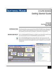
Single Resistor End Line ModeWiring for Multiple Device NC Alarm ZonesTo wire a NC alarm loop with multiple alarm devices to an input circuit, wire the switches inseries and connect a single 1 K Ω EOL resistor in series with the “end of line” alarm device asshown below. This circuit will provide 4-state supervision, Secure, Alert, Shorted, and LineFault. This mode will prevent supervision errors from being reported to the Monitoring Stationwhen Open Loop is detected. In a single end of line resistor input configuration with multipledevices, an Open Loop is seen as an alarm.Multiple Device Alarm Zone:Normally Closed Switches1 KohmInput CircuitAlarm DeviceAlarm DeviceReference Table below for Line Status conditionsThe number of normally closed detection devices that each NC alarm input can supervise islimited only by the resistance of the loop. The total EOL resistance for wire length, contacts, andthe supervision EOL resistor must not exceed 1300 Ω.Single Resistor End Line Mode – Ranges of resistanceStatus Input Resistance CommentShort 0 – 100 ShortLine Fault 101 – 360 Wrong resistorNO Alarm 361 – 750 500 Ω (N/A)Secure 751 – 1450 1K ΩNC Alarm 1451 – 2980 2K Ω (N/A)Line Fault 2981 – 11.8K Wrong resistorAlarm >11.8K Treated like 2K ΩC·CURE 800/8000 V9.4 <strong>UL</strong> <strong>Addendum</strong>31
ConfigurationUse an iSTAR Software Switch in the C·CURE 800 ccure.ini file to instruct the iSTARcontroller to enable the Single Resistor End Line Mode to monitor multiple NC supervisedinputs.• If iSTARSoftwareSwitch3 is enabled (iSTARSoftwareSwitch3=1) and the Activate input onsupervision errors is selected in the input dialog, the system will implement the single endof line resistor monitoring of supervised inputs.• If the Activate input on supervision errors selection on the input screen is not enabled, thenthe Normal state monitoring will be used.<strong>UL</strong> Compliant Supervision:Normally Closed Switches1 KohmInput CircuitAlarm DeviceAlarm DeviceReference Table below for Line Status conditionsFigure 1 – Normally Closed SwitchesCCURE.INIiSTARSoftwareSwitch3 DescriptionAdd a line to the DRIVER section of the ccure.ini file to enable the configurable input translationbehavior. A value of 0 is off and a value of 1 is on. By default, the value is 0 (Off). All other values arereserved.To enable the feature, add the following line to the DRIVER section of the C·CURE.INI file:[Driver]iSTARSoftwareSwitch3=1To disable the feature, add the following line to the C·CURE.INI in the DRIVER section or omit theentry.[Driver]iSTARSoftwareSwitch3=032 C·CURE 800/8000 V9.4 <strong>UL</strong> <strong>Addendum</strong>
iSTAR Backup DatabaseThe software switch setting will be stored in the iSTAR backup database whenever the iSTARdoes a power-down or event-triggered backup.Software ConfigurationWhen Multiple Device Alarm Zone wiring is utilized, the Activate input on supervisionerrors and Send state changes to monitoring station options must be selected as indicated inthe dialog box that appears below.For Multiple DeviceAlarm ZonesC·CURE 800/8000 V9.4 <strong>UL</strong> <strong>Addendum</strong>33
3 RD PARTY LEGACY INPUT SUPERVISION SUPPORTC•CURE 800 version 9.3 and iSTAR eX firmware 4.3.provide support for MDI type SupervisedInput Configurations. This option allows C•CURE systems to reuse previously wired legacyinputs.Definitions, Acronyms, and AbbreviationsNormally Open Input – an input with a contact closure switch that is in the open position whenin the Secure state, and in the closed position in the Alarm state.Normally Closed Input – an input with a contact closure switch that is in the closed positionwhen in the Secure state, and in the open position in the Alarm state.Supervising Resistor – a resistor in the circuit of an input that provides known expected valueswhen in the Secure and Alarm states.Single End-Of-Line input – a supervised input that uses a single supervising resistor either inseries or parallel with the contact closure switch.Dual End-Of-Line input – a supervised input that uses two supervising resistors, typically withone resistor in parallel with the sense switch, and the other resistor in series with the first resistorand switch. Alternatively, one resistor may be series with the switch only, and resistor in parallelwith series resistor and switch.NO – Normally OpenNC – Normally ClosedEOL – End-Of-LineSupport for MDI Type Supervised Input ConfigurationsThe Software House iSTAR controllers are able to support legacy supervised inputconfigurations using 1K and 2K resistors, similar to those used by MDI.The iSTAR controllers can be retrofitted to installations with supervised inputs which had beenpreviously wired for legacy systems.The two types of inputs which are supported are 1K ohm Single End-Of-Line (Single EOL)configurations, and 1K / 2K ohm Double End-Of-Line (Double EOL) configurations.The 1K Single inputs can be wired to any input on an iSTAR Pro or eX.The 1K / 2K Double inputs must be connected to an I/8 board, which is connected to an RM buson any iSTAR.34 C·CURE 800/8000 V9.4 <strong>UL</strong> <strong>Addendum</strong>
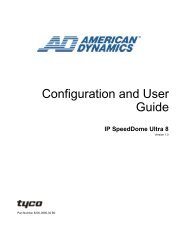
Dual End-Of-Line (NC) ConfigurationsMDI Dual End-Of-Line configurations are wired for Normally Closed (NC) switches, as shownin the diagram below:The above configuration is similar to the Normally Closed case of the Software House standardsupervision configuration, with the following exceptions:• The Alarm state presents a 3K ohm resistance (instead of 2K ohm for Software Housestandard configuration)• The C•CURE 800 system does not recognize the legacy 3 rd party 4K ohm Tamper state.C·CURE 800/8000 V9.4 <strong>UL</strong> <strong>Addendum</strong>35
Dual EOL configuration inputs are adapted to the C•CURE 800 system by connecting theseinputs to an I/8 input board, and modifying the effective resistances presented to the board with a12K ohm bias resistor on each input. After the bias resistor is installed, no other specialconfiguration is required to allow Dual EOL inputs to work under full supervision.Bias Resistor12K ohm resistor (0.250 W or larger) is required for each input configured as a 1K / 2K dualtype supervised input.36 C·CURE 800/8000 V9.4 <strong>UL</strong> <strong>Addendum</strong>
<strong>UL</strong> LISTED ENCRYPTED LINE SECURITY CONFIGURATIONConceptual View of NetworkA conceptual view of the <strong>UL</strong> Listed Encrypted Line <strong>Security</strong> Configuration is shown in thefollowing diagram "Conceptual View of Campus Network."The head end LAN is isolated from the campus network by a firewall and an encrypting router(Software House Model: 0101-0180-01). Communication from the C•CURE 800 server to theiSTAR Pro panel is through an encrypted VPN tunnel between the two encrypting routers(Software House Model: 0101-0180-01 and Software House Model: 0101-0181-01).The Software House Model 0101-0180-01 and 0101-0181-01 routers have been validated ascorrectly implementing the Advanced Encryption Standard (AES) algorithm, specified in theFederal Information Processing Standard Publication 197 (FIPS 197), Advanced EncryptionStandard.Testing was performed by NVLAP accredited Cryptographic Module Testing (CMT)laboratories using the tests found in The Advanced Encryption Standard Algorithm ValidationSuite (AESAVS).The National Institute of Standards and Technology (NIST) has made every attempt to providecomplete and accurate information about the testing implementations; however, it is theresponsibility of the vendor to notify NIST of any necessary changes to its entry.Conceptual View of Campus NetworkC·CURE 800/8000 V9.4 <strong>UL</strong> <strong>Addendum</strong>37
Software House Model 0101-0180-01 RouterThe Software House Model 0101-0180-01 router supports the bandwidth requirements formultiple Fast Ethernet interfaces per slot, time-division multiplexing (TDM) interconnections,and fully integrated power distribution to modules supporting 802.3af Power over Ethernet(PoE), while still supporting the existing portfolio of modular interfaces.The Software House Model 0101-0180-01 router reduces the cost and complexity of managingremote networks by integrating the functions of multiple separate devices into a single compactunit.Software House Model 0101-0180-01 RouterSoftware House Model 0101-0181-01 RouterThe Software House Model 0101-0181-01 router has integrated Federal CommunicationsCommission (FCC) licensed 4.9 GHz and 802.11b/g wireless functionality.The flexible and compact form factor makes the router suitable for integration in vehicles oroutdoor environments. The router provides secure data and video communications across a widerange of different wireless and wired networks. Standards-based mobile IP delivers transparentroaming for mobile applications, and provides security, manageability, and scalability along withinteroperability between networks while allowing for future network expansions and upgrades.Software House Model 0101-0181-01 Router38 C·CURE 800/8000 V9.4 <strong>UL</strong> <strong>Addendum</strong>
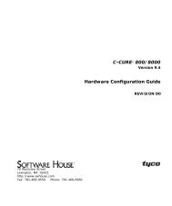
Network ConfigurationThe "<strong>UL</strong> Listed Encrypted Line <strong>Security</strong> Configuration" [2412-2274-01 A0] drawing shows asample wiring diagram for the Software House Router <strong>UL</strong> Test Configuration.• The Software House Model 0101-0181-01 encryption device and iStar Pro control panelmust be installed in the same room.• SWH Model 0101-0181-01 must be powered by a power supply evaluated to <strong>UL</strong> 603 or <strong>UL</strong>1481 with an output range within 10.7 and 29.0 VDC, and provides 2 A continuous and aminimum 4 hours of standby power.• Ethernet connections must be protected by the American Power Conversion Corporation(APCC), Model PNET1 surge suppressors. (See note 1 on the drawing.) Refer to the section"PNET1 Surge Suppressor" on page 40 for safety precautions and installation instructions.• The AC input for the Software House Router Model 0101-0180-01 must be protected by theAmerican Power Conversion Corporation APCC, Model P4 power line surge suppressor.(See note 3 on the drawing.) Refer to section "APCC P4" on page 42 for safety and powerinformation.<strong>UL</strong> Listed Encrypted Line <strong>Security</strong> Configuration [2412-2274-01 A0]C·CURE 800/8000 V9.4 <strong>UL</strong> <strong>Addendum</strong>39
PNET1 Surge Suppressor [2025-0522-01]Safety Precautions• Use only for Ethernet and token ring interface cards, hubs, switches and other LANequipment.• Do not install during a lightning storm! Install in a cool and dry indoor environment.• Turn off power to all equipment to be protected prior to installing the PNet1.The PNet1 mustbe connected to earth ground.• To prevent electric shock when installing the ground wire to the electrical power outletground, turn off electricity to the outlet.• From the electrical panel, switch off the appropriate circuit breaker or remove the fuse forthat circuit/ outlet.InstallationVerify all hardware installation and software configurations before installing the PNet1. Verifythat the system operates correctly with the existing network line.1. Switch off power to the equipment that is to be protected.2. Disconnect the existing network line from the equipment that will be protected.3. Connect this network line to the input jack on the PNet1.4. Connect one end of the supplied 6 inch patch cable to the output jack on the PNet1. This jackis labeled on the PNet1 with a circle and arrow.5. Connect the other end of the patch cable to the input jack on the network equipment that is tobe protected.6. Connect the green/yellow ground wire to ground.Note: To fully protect your system, all surge protectors must be properly grounded. If yourelectrical system is a two- wire non-grounded system, the PNet1 may be left ungrounded.However, please note that if the PNet1 ground wire is not connected to earth ground, thelongitudinal (line to ground) surge protection will be rendered ineffective.40 C·CURE 800/8000 V9.4 <strong>UL</strong> <strong>Addendum</strong>
PNET1 InstallationPNET1 PhotographC·CURE 800/8000 V9.4 <strong>UL</strong> <strong>Addendum</strong>41
APCC P4 [2025-0521-01]APC Power Protection• Lightning and Surge ProtectionLightning and surge protection devices help prevent equipment damage from powersurges and spikes.• IEEE let-through ratings and regulatory agency complianceAPC surge protectors undergo stringent testing by IEEE, and are awarded "let-throughratings", which indicate the maximum voltage level that can possibly reach yourequipment after a surge or voltage spike has passed through a surge protector. LowerIEEE let-through ratings indicate better protection and performance.The APC Essential SurgeArrest series offers optimal performance with a let-throughrating of less than 330V for North American products, and a rating of less than 15% forproducts sold worldwide. All APC products comply with local agency safetyrequirements, including <strong>UL</strong> in North America and CE/Kema/Gost/C-tick/A-Tick/Telepermit in their respective regions.• Data-line ProtectionProtection of data lines (Ethernet, Coaxial and Phone lines) ensures complete protectionof your equipment from surges. It is very important to protect your equipment from “backdoor” surges traveling through data lines, as they can be as damaging to your equipmentas surges traveling over power lines.• Noise FilteringSurge Protector devices attenuate EMI/RFI line noise that can cause data errors andkeyboard lockups, ensuring better performance of protected equipment.42 C·CURE 800/8000 V9.4 <strong>UL</strong> <strong>Addendum</strong>
APC Safety• Catastrophic Event ProtectionSurgeArrest components such as MOVs and Thermal fuse ensure instantaneous reactionto lightning strikes and wiring faults. If the surge components are damaged due to powerspike or over voltage, excess power cannot reach your equipment.• Fail Safe ModeMany surge suppressors continue to let power through even after their circuits have beendamaged, leaving your equipment exposed to future surges. The APC SurgeArrest is failsafe, which means that once the circuit of an APC SurgeArrest has been compromised,the unit disconnects equipment from the power supply ensuring that no damaging surgesreach your equipment.• Protection Working IndicatorIf this indicator goes out, surge suppression circuitry has been damaged by a heavy strikeor power line surge.• Building Wiring Fault IndicatorIf this indicator goes out, surge suppression circuitry has been damaged by a heavy strikeor power line surge.Power Supply for Software House Model 0101-01881-01SWH Model 0101-0181-01 must be powered by a power supply evaluated to <strong>UL</strong> 603 or <strong>UL</strong>1481 with an output range within 10.7 and 29.0 VDC, and provides 2 A continuous and aminimum 4 hours of standby power.Power Supply for Software House Model 0101-01880-01The SWH Model 0101-01880-01 router is powered by a UPS system located at the installationsite. This UPS meets the 4 hour minimum stand-by time required by <strong>UL</strong> 1076.C·CURE 800/8000 V9.4 <strong>UL</strong> <strong>Addendum</strong>43