Configuration and User Guide - Tyco Security Products
Configuration and User Guide - Tyco Security Products
Configuration and User Guide - Tyco Security Products
- No tags were found...

You also want an ePaper? Increase the reach of your titles
YUMPU automatically turns print PDFs into web optimized ePapers that Google loves.
Table of ContentsIntroduction 1Overview . . . . . . . . . . . . . . . . . . . . . . . . . . . . . . . . . . . . . . . . . . . . . . . . . . . . . . . . . 1-1Features . . . . . . . . . . . . . . . . . . . . . . . . . . . . . . . . . . . . . . . . . . . . . . . . . . . . . . . . . . 1-1Connections . . . . . . . . . . . . . . . . . . . . . . . . . . . . . . . . . . . . . . . . . . . . . . . . . . . . 1-1ACC Compression. . . . . . . . . . . . . . . . . . . . . . . . . . . . . . . . . . . . . . . . . . . . . . . . 1-1Video Loss Detection . . . . . . . . . . . . . . . . . . . . . . . . . . . . . . . . . . . . . . . . . . . . . 1-1Frame Rates . . . . . . . . . . . . . . . . . . . . . . . . . . . . . . . . . . . . . . . . . . . . . . . . . . . . 1-2Resolutions . . . . . . . . . . . . . . . . . . . . . . . . . . . . . . . . . . . . . . . . . . . . . . . . . . . . . 1-2B<strong>and</strong>width Throttling . . . . . . . . . . . . . . . . . . . . . . . . . . . . . . . . . . . . . . . . . . . . . . 1-2Advanced Features . . . . . . . . . . . . . . . . . . . . . . . . . . . . . . . . . . . . . . . . . . . . . . . 1-2Web <strong>Configuration</strong>. . . . . . . . . . . . . . . . . . . . . . . . . . . . . . . . . . . . . . . . . . . . . . . . 1-2Recommended <strong>Configuration</strong> . . . . . . . . . . . . . . . . . . . . . . . . . . . . . . . . . . . . . . . 1-2Installation 2Installation process . . . . . . . . . . . . . . . . . . . . . . . . . . . . . . . . . . . . . . . . . . . . . . . 2-2Web <strong>Configuration</strong> 3Log in to the IPSDU8. . . . . . . . . . . . . . . . . . . . . . . . . . . . . . . . . . . . . . . . . . . . . . 3-2<strong>User</strong> Front Page. . . . . . . . . . . . . . . . . . . . . . . . . . . . . . . . . . . . . . . . . . . . . . . . 3-3Administrator Front Page . . . . . . . . . . . . . . . . . . . . . . . . . . . . . . . . . . . . . . . . . 3-4Checking camera feeds using Live Video function . . . . . . . . . . . . . . . . . . . . . . . 3-4Controlling the SDU8 on the Live Video page . . . . . . . . . . . . . . . . . . . . . . . . . 3-7Pattern <strong>and</strong> Preset Camera Controls. . . . . . . . . . . . . . . . . . . . . . . . . . . . . . . . 3-9Configuring an SDU8 Camera. . . . . . . . . . . . . . . . . . . . . . . . . . . . . . . . . . . . . . 3-11Configuring the IPSDU8 . . . . . . . . . . . . . . . . . . . . . . . . . . . . . . . . . . . . . . . . . . 3-11<strong>Security</strong> (adding or editing user accounts) . . . . . . . . . . . . . . . . . . . . . . . . . . . . 3-12Configuring the TCP/IP settings. . . . . . . . . . . . . . . . . . . . . . . . . . . . . . . . . . . 3-14Configuring the Video Input . . . . . . . . . . . . . . . . . . . . . . . . . . . . . . . . . . . . . . 3-16Event Input <strong>Configuration</strong> . . . . . . . . . . . . . . . . . . . . . . . . . . . . . . . . . . . . . . . 3-17Diagnostic LEDs <strong>Configuration</strong> . . . . . . . . . . . . . . . . . . . . . . . . . . . . . . . . . . . 3-19Saving the IPSDU8 configuration . . . . . . . . . . . . . . . . . . . . . . . . . . . . . . . . . 3-20Canceling configuration changes. . . . . . . . . . . . . . . . . . . . . . . . . . . . . . . . . . 3-21Backing up the configuration . . . . . . . . . . . . . . . . . . . . . . . . . . . . . . . . . . . . . . . 3-21Restoring configuration from a data file . . . . . . . . . . . . . . . . . . . . . . . . . . . . . 3-22Upgrading or Downgrading the Firmware . . . . . . . . . . . . . . . . . . . . . . . . . . . 3-23vii
Table of ContentsProcedure 3-4 Controlling dome Pan/Tilt via a mouse usingthe Live Video page . . . . . . . . . . . . . . . . . . . . . . . . . . . . . . . . . . . . . . . . . . . . . . 3-8Procedure 3-5 Zooming a dome via the mouse scroll wheelusing the Live Video page . . . . . . . . . . . . . . . . . . . . . . . . . . . . . . . . . . . . . . . . . 3-9Procedure 3-6 Selecting a dome pattern using the Live Video page . . . . . . . . . 3-9Procedure 3-7 Defining a dome pattern using the Live Video page . . . . . . . . . . 3-9Procedure 3-8 Selecting a dome preset using the Live Video page . . . . . . . . 3-10Procedure 3-9 Defining a dome preset using the Live Video page . . . . . . . . . 3-10Procedure 3-10 Configuring a dome using the Live Video page . . . . . . . . . . . 3-11Procedure 3-11 Accessing the IPSDU8 <strong>Configuration</strong> page . . . . . . . . . . . . . . 3-11Procedure 3-12 Adding a new user or editing an existing user’s details . . . . . 3-13Procedure 3-13 Configuring the TCP/IP settings . . . . . . . . . . . . . . . . . . . . . . . 3-14Procedure 3-14 Configuring the Video Input . . . . . . . . . . . . . . . . . . . . . . . . . . 3-16Procedure 3-15 Changing the Camera Address on the Live Video page . . . . 3-17Procedure 3-16 Configuring the Event Inputs . . . . . . . . . . . . . . . . . . . . . . . . . 3-17Procedure 3-17 Configuring the Diagnostic LEDs . . . . . . . . . . . . . . . . . . . . . . 3-19Procedure 3-18 Saving the IPSDU8 configuration . . . . . . . . . . . . . . . . . . . . . . 3-20Procedure 3-19 Canceling configuration changes . . . . . . . . . . . . . . . . . . . . . . 3-21Procedure 3-20 Backing up the configuration . . . . . . . . . . . . . . . . . . . . . . . . . 3-21Procedure 3-21 Restoring configuration from a data file . . . . . . . . . . . . . . . . . 3-22Procedure 3-22 Upgrading/Downgrading the Firmware . . . . . . . . . . . . . . . . . . 3-23Procedure 4-1 Restoring the IPSDU8 factory defaults . . . . . . . . . . . . . . . . . . . . 4-2List of TablesTable 1-1 Frame rates . . . . . . . . . . . . . . . . . . . . . . . . . . . . . . . . . . . . . . . . . . . . 1-2Table 1-2 Resolution . . . . . . . . . . . . . . . . . . . . . . . . . . . . . . . . . . . . . . . . . . . . . . 1-2Table 5-1 Technical Specifications . . . . . . . . . . . . . . . . . . . . . . . . . . . . . . . . . . . 5-3Table 5-2 Indoor <strong>and</strong> Outdoor alarm details . . . . . . . . . . . . . . . . . . . . . . . . . . . . 5-4Table 5-3 Certification <strong>and</strong> Regulations . . . . . . . . . . . . . . . . . . . . . . . . . . . . . . . 5-4Index 6ix
Table of Contentsx<strong>Configuration</strong> <strong>and</strong> <strong>User</strong> <strong>Guide</strong>
1 IntroductionOverviewThe IP SpeedDome Ultra 8 (hereafter referred to as IPSDU8) offers a high performance IP videostream for one analog video source. The IPSDU8 is specifically designed for security video whichproduces compressed video that is up to nine times more efficient than MPEG-4 <strong>and</strong> MJPEGproducts.The IPSDU8 is an ACC video encoder that converts analog video from our existing cameras <strong>and</strong>domes into a network compatible IP signal used by Intellex IP <strong>and</strong> the VideoEdge NVR systems.An Intellex IP System offers a highly reliable digital video management system with the flexibility,scalability, <strong>and</strong> improved performance of IP. It is compatible with Network Client <strong>and</strong> all thirdparty applications developed using the Intellex API, so it is remotely accessible, network ready,<strong>and</strong> easy to integrate with other equipment.The VideoEdge NVR is a scalable <strong>and</strong> open IP based platform. It can support as many as 128cameras per server, including IP cameras, IP domes, analog cameras with IP encoders as well asthe VideoEdge IP Encoder <strong>and</strong> megapixel cameras. The network appliance architecture <strong>and</strong>embedded Linux operating system provide a secure, robust solution for high availability enterpriseapplications.The IPSDU8 is not available in Power over Ethernet (PoE).FeaturesConnectionsThe IPSDU8 has the following physical connections:• 4 event (alarm) inputs;• 3 event (alarm) outputs for Indoor, <strong>and</strong> 1 (relay contact) for Outdoor;• 3 wire 24VAC power supply; <strong>and</strong>• 1 RJ-45 network connection — for connection to the 10/100 BaseT Ethernet network.ACC CompressionThree quality levels (Super, Normal, <strong>and</strong> Extended Record) are available for the camera.Two sensitivity levels (Normal <strong>and</strong> High) are available for the camera.Video Loss DetectionIn the event of video loss, an alarm is generated. The alarm is automatically cleared when thevideo is restored.1-1
IntroductionFrame RatesTable 1-1 Frame ratesNTSCPAL30 IPS @ 4 CIF 25 IPS @ 4 CIF30 IPS @ 2 CIF 25 IPS @ 2 CIF30 IPS @ CIF 25 IPS @ CIFNoteThe IPSDU8 supports a maximum of 30/25 (NTSC/PAL) images per second per video channel at4 CIF. Actual frame rates may be less due to high motion.ResolutionsTable 1-2 ResolutionNTSCPAL320 x 240 pixels (Note 1) 320 x 288 pixels (Note 1)352 x 240 pixels 352 x 288 pixels640 x 240 pixels (Note 1) 640 x 288 pixels (Note 1)704 x 240 pixels (Note 1) 704 x 288 pixels (Note 1)640 x 480 pixels 640 x 576 pixels704 x 480 pixels 704 x 576 pixelsNote 1For use with Live Video feature only.B<strong>and</strong>width ThrottlingThe IPSDU8 supports b<strong>and</strong>width throttling <strong>and</strong> is set on a individual camera <strong>and</strong> client basis. Themaximum b<strong>and</strong>width is selectable between 30 kb/s <strong>and</strong> 4 Mb/s. The B<strong>and</strong>width throttling isconfigured on the Intellex IP or VideoEdge NVR.Advanced Features• PTZ camera control via the network cable.• Event h<strong>and</strong>ling: four TTL (transistor-transistor logic) input alarms, three to the SDU8 <strong>and</strong> one tothe Encoder module; <strong>and</strong> up to three output alarms, depending on the housing.Web <strong>Configuration</strong>IPSDU8’s web configuration page allows you to configure settings <strong>and</strong> view live video. Refer topage 3-1, Web <strong>Configuration</strong> for more information.Recommended <strong>Configuration</strong>The recommended configuration for the IPSDU8 is three IP Encoders (with 12 static cameras) <strong>and</strong>four domes which pan simultaneously.1-2 <strong>Configuration</strong> <strong>and</strong> <strong>User</strong> <strong>Guide</strong>
2 InstallationThe IPSDU8 can be installed one of three ways: indoor hard mount, using an RHOPN pendantmount, or using an ROENDC end cap assembly.Up to 16 IPSDU8s, supplying a maximum of 16 video inputs, can be connected to one Intellex IPunit, or up to 128 IPSDU8 units can be connected to one VideoEdge NVR unit, depending onthe licensing.NoteMore than four domes moving at one time may result in lost frames.Detailed installation instructions can be found in the Installation <strong>Guide</strong> 8200-0885-01. The basicsteps involved in installing this product are outlined below:• Install the hardware• Configure the software <strong>and</strong> camera settings.The full installation process is detailed in the flowchart on the next page.2-1
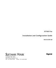
InstallationInstallation processEnsure the required power, network <strong>and</strong> alarm cables areinstalled <strong>and</strong> the network cable is labelled <strong>and</strong> disconnected atthe network patch panel or access point.Remove the IPSDU8, dome camera <strong>and</strong> corresponding mount fromtheir packaging.Referring to the IPSDU8 Installation <strong>Guide</strong> (8200-0885-01) installthe following:• Mount (which has PCB <strong>and</strong> cables installed)• SDU8• BubbleNOIs the IPSDU8 on thesame subnet addressas the Intellex orVideoEdge NVR?YESConnect a laptop to theIPSDU8 Ethernet cablelocated at the patchpanel or access point.Connect the IPSDU8Ethernet cable intothe network patchpanel or access point.Open a browser window <strong>and</strong> enter the IP address of the IPSDU8,192.168.1.80.Refer to Web <strong>Configuration</strong> (Chapter 3) <strong>and</strong> configure the followingsettings on the IPSDU8:• TCP/IP settings• Video Input (if applicable)• Event Inputs (if applicable)Within the browser window navigate to the Live video page <strong>and</strong> followthe Web <strong>Configuration</strong> chapter to access the SDU8 dome configurationmenu, then using the SDU8 <strong>User</strong> Manuals, configure the requireddome settings.If a laptop was used to configure the IPSDU8, disconnect the laptop<strong>and</strong> connect the IPSDU8 Ethernet cable into the network patch panelor access point.Refer to the Intellex/VideoEdge NVR Setup <strong>Guide</strong> <strong>and</strong> follow theprocedure for adding a IPSDU8.Figure 2-1 Installation process flowchart2-2 <strong>Configuration</strong> <strong>and</strong> <strong>User</strong> <strong>Guide</strong>
3 Web <strong>Configuration</strong>This section details how to configure the IPSDU8 using the built in Web <strong>Configuration</strong> feature.At this release, the supported web browsers are as follows:• Microsoft Internet Explorer 6.x• Microsoft Internet Explorer 7.xMinimum PC Requirements:• Processor: 2GHz Intel Pentium 4• Memory: 512MB• Operating System: Microsoft Windows 2000 Professional, Microsoft Windows XPProfessional, Microsoft Vista.NoteJavaScript must be enabled to allow the correct viewing of the web configuration pages.NoteWeb <strong>Configuration</strong> sessions time out after a period of inactivity.NoteOnly users with administrative rights can access the Web <strong>Configuration</strong> pages.NoteOnly one user may access the Web <strong>Configuration</strong> pages at a time.3-1
Web <strong>Configuration</strong>Log in to the IPSDU8Procedure 3-1 Logging in to the IPSDU81 Open the browser <strong>and</strong> enter the IP address 192.168.1.80. This is the default address of theIPSDU8 Login Page.The main Login page will be displayed as shown in Figure 3-1.NoteFigure 3-1 Login pageIf any alarms or warnings are present on the IPSDU8 then these will also be displayed on theLogin page, an example is shown in Figure 3-2.Figure 3-2 Login page with warnings3-2 <strong>Configuration</strong> <strong>and</strong> <strong>User</strong> <strong>Guide</strong>
Web <strong>Configuration</strong>2 Enter the appropriate <strong>User</strong> Login Name <strong>and</strong> Password, then select LOGIN.Depending on the access rights of the user, the IPSDU8 will display either the Administrator orthe <strong>User</strong> front page. Both options are described on the following pages.NoteThe default user name is Administrator <strong>and</strong> the default password is MERLIN.<strong>User</strong> Front PageOnce a <strong>User</strong> has logged in, Figure 3-3 will be displayed.Figure 3-3 <strong>User</strong> Front PageThe options available to the <strong>User</strong> are:• Live Video — allows testing of the attached SDU8 camera by viewing live video;• Refresh — provides a method of updating the System Status of the IPSDU8;• Logout.3-3
Web <strong>Configuration</strong>Administrator Front PageOnce an Administrator has logged in Figure 3-4 will be displayed.Figure 3-4 Administrator Front PageThe options available to the Administrator are:• Live Video — allows the testing of the attached SDU8 camera by viewing live video;• <strong>Configuration</strong> — configures the IPSDU8;• Backup Config — allows the IPSDU8 configuration to be saved to a data file;• Update Firmware — allows the IPSDU8 firmware to be updated;• Restart — restarts the IPSDU8;• Refresh — provides a method of updating the System Status of the IPSDU8;• Logout.Checking camera feeds using Live Video functionThe Live Video page provides a simple way to test the video input from the connected SDU8camera. This Live Video page is not intended to be the primary way of viewing the video on theIPSDU8; this should be performed using an Intellex IP or a VideoEdge NVR.3-4 <strong>Configuration</strong> <strong>and</strong> <strong>User</strong> <strong>Guide</strong>
Web <strong>Configuration</strong>The Live Video pages are accessible to any authorized user.NoteTo be able to view the Live Video page JavaScript must be installed <strong>and</strong> enabled on the computerrunning the browser session.Procedure 3-2 Checking the SpeedDome feed using the Live Video function1 Log in to the IPSDU8 using an appropriate user Name <strong>and</strong> Password; for more details refer toLog in to the IPSDU8 on page 3-2.2 Select Live Video from the IPSDU8 Front Page.The Live Video page is displayed, as shown in Figure 3-5.Figure 3-5 Live Video page3-5
Web <strong>Configuration</strong>NoteThe first time you log in, or if there has been a complete power cycle, the camera needs torecognize its control protocol. The “checking network type” message will be displayed on screenfor approximately ten seconds. To clear this message click twice on the dome symbol .Figure 3-6 Checking Network Type3 The default Quality is set to Normal. To change the Quality setting select the required optionfrom the Quality drop down menu. The options are Extended (for longer recording times),Normal or Super (for highest quality image).4 The default Sensitivity is set to High. To change the Sensitivity setting select either High (forhighest quality image with a much larger file size) or Normal (video is recorded through asophisticated noise filter) from the Sensitivity drop down menu.5 The default Resolution is 1 CIF (320). To change the Resolution setting select the requiredoption from the Resolution drop down menu. The options are 1 CIF (320), 1 CIF (352), 2 CIF(640), 2 CIF (704), 4 CIF (640) or 4 CIF (704). A thin black line may be visible at the side of thevideo pane if an incorrect setting has been chosen.3-6 <strong>Configuration</strong> <strong>and</strong> <strong>User</strong> <strong>Guide</strong>
Web <strong>Configuration</strong>6 If required select the DirectDraw checkbox. DirectDraw consumes less CPU time on the webbrowser while drawing video.NoteChanging the Quality, Sensitivity, Resolution or Direct Draw settings only affect what is beingdisplayed on the Live Video page. Changing these settings does not affect the video being sentby the IPSDU8 to the Intellex IP or VideoEdge NVR.7 Select Front Page to return to the IPSDU8 Front Page or Logout to exit the screen.Controlling the SDU8 on the Live Video pageThe SDU8 may be controlled using the on-screen controls in the video window once the VideoInputs <strong>and</strong> Camera Control <strong>Configuration</strong> settings have been completed. Refer to Configuring theVideo Input on page 3-16 for more information.SDU8 ControlsThe following information details the various controls that are available for the on-screen SDU8control.NoteIf another user is operating the dome, you will not be able to control it.The dome symbolappears with video from a camera with dome control.Procedure 3-3 Controlling the dome camera on the Live Video page1 Click in the camera’s pane.2 Click the control item on the overlay..IrisZoomFlips the camera 180°Closes the dome control overlay(Exit)Opens the dome configurationmenuOpens the pattern menuPan/Tilt controlFocusOpens the preset menu3-7
Web <strong>Configuration</strong>IrisZoomOpenAuto Iris <strong>and</strong> Focus (on cameras which supportthis feature)CloseInOutFocusNearFarPan/Tilt MovementPan/Tilt (outer rim)Controlling the Pan/Tilt Control via MouseProcedure 3-4 Controlling dome Pan/Tilt via a mouse using the Live Video page1 Select in the camera’s pane.2 Float the cursor over the center of the video pane. The Cursor Origin Mark appears.3 Click <strong>and</strong> drag the cursor to set the direction <strong>and</strong> speed, then release.• The camera’s movement speed increases proportionally with the arrow’s distance from thecursor origin mark.• The camera’s direction is relative to cursor origin mark.NoteVaried speed relative to distance from the cursor origin mark is only available if it is supportedby the camera <strong>and</strong> implemented in the PTZ protocol.3-8 <strong>Configuration</strong> <strong>and</strong> <strong>User</strong> <strong>Guide</strong>
Web <strong>Configuration</strong>Zoom via Mouse Scroll WheelProcedure 3-5 Zooming a dome via the mouse scroll wheel using the Live Videopage1 Point the camera at a target.2 Scroll the mouse wheel forwards (zoom in) <strong>and</strong> backwards (zoom out).Pattern <strong>and</strong> Preset Camera ControlsA Preset is a pre-positioned camera scene that you program for cameras installed with pan/tilt <strong>and</strong>motorized lens capability. A Pattern is a sequence of pan, tilt, zoom, focus <strong>and</strong> iris movementsfrom a single, programmable dome. The dome learns these movements during programming forlater execution.NoteOnly Presets <strong>and</strong> Patterns that have been set up for the particular camera can be selected. UseIntellex, Network Client, a Touch Tracker, or the Live View page to program presets <strong>and</strong> patterns.Selecting a PatternProcedure 3-6 Selecting a dome pattern using the Live Video page1 Click to open the Primary Camera Control menu.2 Click Pattern for the pattern menu:3 Select a pattern number.4 Click to run the pattern once or to run the pattern continuously.5 Click Exit to close the Pattern menu.6 Click to close the Primary Camera Control menu.Defining a PatternProcedure 3-7 Defining a dome pattern using the Live Video page1 Click to open the Primary Camera Control.2 Position the camera for the pattern’s start position.3 Click <strong>and</strong> select an index for pattern.4 Click Define Pattern . The Pattern Definition Menu appears.It resembles the Primary Camera Control menu, except for Start <strong>and</strong> Stop.5 Click Start to begin programming the pattern. Use any displayed controls to define thepattern’s behavior.3-9
Web <strong>Configuration</strong>6 To end the pattern, click Stop . The “Replace pattern” message appears.7 To keep the new pattern, click Yes, or select No.8 Click to close the pattern’s definition menu.9 To test the new pattern, select the pattern number <strong>and</strong> click .10 Click to close the Pattern menu.11 Click to close the Primary Camera Control menu.Selecting a PresetProcedure 3-8 Selecting a dome preset using the Live Video page1 Click to open the Primary Camera Control menu.2 Click Preset to display the preset menu.3 Select a preset number.4 Click to move the camera to the preset position.5 Click to close the Preset menu.6 Click to close the Primary Camera Control menu.Defining a PresetProcedure 3-9 Defining a dome preset using the Live Video page1 Click to open the Primary Camera Control menu.2 Position the camera for your preset.3 Click to display the preset menu.4 Select a preset number.5 Click Define Preset to define a preset at this index.6 When the “Replace preset” message appears, click Yes to program the preset.The number of available presets is device-dependent.3-10 <strong>Configuration</strong> <strong>and</strong> <strong>User</strong> <strong>Guide</strong>
Web <strong>Configuration</strong>Configuring an SDU8 CameraThe SDU8 cameras can access the dome configuration menu (see the Intellex Installation <strong>and</strong><strong>Configuration</strong> <strong>Guide</strong> 8200-0732-01).Procedure 3-10 Configuring a dome using the Live Video page1 Select the camera. Click .2 Click <strong>Configuration</strong> Menu .3 Navigate to items in the menu using Pan/Tilt . Select the items using Focus . UseZoom to modify the values.4 Accept or reject the modified values.5 Repeat steps 3 <strong>and</strong> 4 until the camera is configured.6 Close the Dome <strong>Configuration</strong> Menu.Configuring the IPSDU8The main configuration page of the IPSDU8 contains all the settings necessary to configure theIPSDU8.The configured items are:• <strong>Security</strong>• TCP/IP Network• Video Input• Event Input• Diagnostic LEDs.NoteAny changes to the configuration are only saved when Save Config is selected.Procedure 3-11 Accessing the IPSDU8 <strong>Configuration</strong> page1 Log in to the IPSDU8, refer to Procedure 3-1.2 Select <strong>Configuration</strong> from the Front Page.The <strong>Configuration</strong> main page will be displayed, as shown in Figure 3-7.NoteTo view the bottom of the Main <strong>Configuration</strong> page it may be necessary to use the scroll barson the browser window.3-11
Web <strong>Configuration</strong>Figure 3-7 Main <strong>Configuration</strong> page<strong>Security</strong> (adding or editing user accounts)The <strong>Security</strong> settings in the IPSDU8 allow for the addition of new users <strong>and</strong> the editing or deletionof existing users.The two levels of user access available are Administrator <strong>and</strong> View Video Only.• Administrator — allows full access to all features of the IPSDU8;• View Video Only — access is restricted to the Live Video feature only.NoteIt is only possible to add up to 10 user accounts, including the built-in Administrator’s account.After 10 users have been added the Create New <strong>User</strong> button will be disabled until an existing userhas been deleted.NoteIt is recommended that a new Administrator account be created or the default Administratoraccount user Name or Password be changed.3-12 <strong>Configuration</strong> <strong>and</strong> <strong>User</strong> <strong>Guide</strong>
Web <strong>Configuration</strong>Procedure 3-12 Adding a new user or editing an existing user’s details1 Ensure that the browser is displaying the <strong>Configuration</strong> page (if not refer to Procedure 3-11).2 Select Edit from within the <strong>Security</strong> section.The <strong>Security</strong> pages will be displayed, as shown in Figure 3-8.Figure 3-8 IPSDU8 <strong>Configuration</strong>: <strong>Security</strong> Detail3 Select Create New <strong>User</strong> to add a new user or select the Edit button to the left of an existinguser.The Add/Edit page will be displayed, as shown in Figure 3-9.Figure 3-9 Add/Edit <strong>User</strong> page4 Enter or change the Name <strong>and</strong> Password fields as required.5 Select Enabled from the State drop down menu to enable the user’s account. SelectingDisabled will disable the user’s account preventing them from logging in. The default setting isEnabled for new user accounts.3-13
Web <strong>Configuration</strong>6 If the user is to have administration rights select Enabled from the Administrator drop downmenu. The default setting is Disabled for new user accounts.7 Select Done to return to the main <strong>Security</strong> Detail page, as shown in Figure 3-8.8 If all users have been added or updated then select Done to return to the IPSDU8 Main<strong>Configuration</strong> page.9 If all the required changes have been made to the IPSDU8 configuration then select SaveConfig to ensure all changes have been saved. Refer to Procedure 3-18 for more informationon saving configuration changes.NoteAt least 1 of the 10 accounts must have administrator rights.Configuring the TCP/IP settingsThe TCP/IP Network (Ethernet) configuration page allows the configuration of the followingTCP/IP Settings:• Server Name• IP Source• IP Address• IP Mask• Gateway IP• DNS IP.The TCP/IP page will also display the MAC address of the IPSDU8.Procedure 3-13 Configuring the TCP/IP settings1 Ensure that the browser is displaying the <strong>Configuration</strong> page (if not refer to Procedure 3-11).2 Select Edit from within the TCP/IP section.The TCP/IP <strong>Configuration</strong> page will be displayed, as shown in Figure 3-10.3-14 <strong>Configuration</strong> <strong>and</strong> <strong>User</strong> <strong>Guide</strong>
Web <strong>Configuration</strong>Figure 3-10 TCP/IP <strong>Configuration</strong> page3 The Server Name is the network name given to the IPSDU8 on the TCP/IP network. Thedefault Server Name is the product name, e.g. ADSDUIH, followed by the last 6 digits of theMAC address.Enter a new Server Name by deleting the current name <strong>and</strong> typing a new Server Name.4 Select the desired IP Source from the IP Source drop down list. The options are DHCP orManual. If DHCP is selected the remainder of the TCP/IP settings will be obtained from theDHCP server. If manual is selected the remainder of the TCP/IP settings will have to beentered manually.5 Enter the IP Address in the format xxx.xxx.xxx.xxx.6 Enter the IP Mask in the format xxx.xxx.xxx.xxx.7 Enter the Gateway IP in the format xxx.xxx.xxx.xxx. Gateway IP is the IP address of the localgateway.8 Enter the DNS IP in the format xxx.xxx.xxx.xxx. DNS IP is the IP address of the DNS Server.NoteIfThen go toDHCP is selected Step 9Manual is selected Step 5At this release the DNS IP Address is not used <strong>and</strong> can be left at the default setting.9 Select Done to return to the IPSDU8 Main <strong>Configuration</strong> page.10 If all the required changes have been made to the IPSDU8 configuration then select SaveConfig to ensure all changes have been saved. Refer to Procedure 3-18 for more informationon saving configuration changes.3-15
Web <strong>Configuration</strong>Configuring the Video InputThe Video Input Detail page allows configuration of the video format, the camera control protocol<strong>and</strong> the camera address.When using 4 CIF the video is automatically deinterlaced to give a better motion quality.Procedure 3-14 Configuring the Video Input1 Ensure that the browser is displaying the <strong>Configuration</strong> page (if not refer to Procedure 3-11).2 From within the Video Inputs section select the Edit button.The Video Input 1 Detail page is displayed, as shown in Figure 3-11.Figure 3-11 Video Input Detail page3 Enter the required Name for the Video Input.4 Select the required Video Format from the drop down menu. The options are Auto, NTSC <strong>and</strong>PAL. The default setting is Auto, which will automatically detect the incoming video streamformat.5 If using 4 CIF the video is automatically deinterlaced to give better quality on motion. To disabledeinterlacing select Disable from the Deinterlace (4 CIF) drop down menu.6 Select the required PTZ Protocol from the drop down menu. The options are SensorNet ornone. The default setting is SensorNet.7 Ensure the camera address matches the address on the SDU8.NoteIt is recommended that all camera addresses be left at the default of 1.8 Select Done to return to the Main <strong>Configuration</strong> page.9 Select Save Config to ensure all changes have been saved. Refer to Procedure 3-18 for moreinformation on saving configuration changes.3-16 <strong>Configuration</strong> <strong>and</strong> <strong>User</strong> <strong>Guide</strong>
Web <strong>Configuration</strong>Procedure 3-15 Changing the Camera Address on the Live Video pageA camera address should only be changed to clear data (e.g. presets <strong>and</strong> patterns) from the baseIO flash memory, or if a new SDU8 needs to be uploaded with data from the original base IO flashmemory.CautionThe camera address needs to be changed both on the SDU8 itself <strong>and</strong> on the web GUI, via theLive Video page for camera control to be maintained.To change the SDU8 address, refer to SpeedDome ® Ultra 8 Camera Dome Operator’s <strong>Guide</strong>,8200-0600-01.1 Ensure that the browser is displaying the <strong>Configuration</strong> page (if not refer to Procedure 3-11).2 From within the Video Inputs section select the Edit button.The Video Input 1 Detail page is displayed, as shown in Figure 3-11.3 Under Camera Control <strong>Configuration</strong>, type the new address in the Camera Address text box;the range is from 0 - 254.4 Select Done to return to the Main <strong>Configuration</strong> page.5 Once the required changes have been made to the IPSDU8 configuration select Save Configto ensure all changes have been saved. Refer to Procedure 3-18 for more information onsaving configuration changes.Event Input <strong>Configuration</strong>The Event Input feature is used to set triggers on the IPSDU8 which are activated by a change instate of the attached device. An example of an Event Input could be the use of a door sensor,which, when the door is opened, triggers an event on the IPSDU8 which in turn can be monitoredby the Intellex IP or VideoEdge NVR to start recording on the associated video input at a higherrate.There is only one Event Input that goes through the IPSDU8 <strong>and</strong> can be configured with the Web<strong>Configuration</strong> tool. Three other Event Inputs are wired directly to the SDU8, <strong>and</strong> should beconfigured via the Live Video. For more information refer to the Operator’s <strong>Guide</strong> 8200-0600-01.Procedure 3-16 Configuring the Event Inputs1 Ensure that the browser is displaying the <strong>Configuration</strong> page (if not refer to Procedure 3-11).2 Select the Edit button, from within the Event Inputs section, to configure the Event Input.The Event Input Detail page is displayed, as shown in Figure 3-12.3-17
Web <strong>Configuration</strong>Figure 3-12 Event Input Detail page3 Enter the required Name for the Event Input.4 Select the required State from the drop down menu. The options are Enabled or Disabled. Thedefault setting is Disabled.5 Select the required Active state from the drop down menu. The options are High or Low. Thedefault setting is Low.6 Select Done to return to the Main <strong>Configuration</strong> page.7 Once the required changes have been made to the IPSDU8 configuration select Save Configto ensure all changes have been saved. Refer to Procedure 3-18 for more information onsaving configuration changes.3-18 <strong>Configuration</strong> <strong>and</strong> <strong>User</strong> <strong>Guide</strong>
Web <strong>Configuration</strong>Diagnostic LEDs <strong>Configuration</strong>LEDs on the underside of the mounting base allow you to check for power <strong>and</strong> data during theinstallation process. LEDs on the I/O board indicate whether wiring is correct, reversed, open orgrounded; refer to LED Status Descriptions on page 5-2.Procedure 3-17 Configuring the Diagnostic LEDs1 Ensure that the browser is displaying the <strong>Configuration</strong> page (if not refer to Procedure 3-11).2 Select the Edit button, from within the Diagnostic LEDs section, to configure the LEDs.The Diagnostic LED Detail page is displayed, as shown in Figure 3-13.Figure 3-13 Diagnostic LED Detail page3 Select whether the LEDs are to be enabled or disabled. The default is enabled.4 Select Done to return to the Main <strong>Configuration</strong> page.5 Once the required changes have been made to the IPSDU8 configuration select Save Configto ensure all changes have been saved. Refer to Procedure 3-18 for more information onsaving configuration changes.NoteOnce the IPSDU8 has been configured the LEDs should be disabled during normal use, sothey do not interfere with the video quality.3-19
Web <strong>Configuration</strong>Saving the IPSDU8 configurationIf any of the IPSDU8 configuration settings have been changed, the IPSDU8 configuration must besaved. Once the configuration has been saved the IPSDU8 will restart to use the saved settings.Procedure 3-18 details the steps required to save the IPSDU8 <strong>Configuration</strong>.Procedure 3-18 Saving the IPSDU8 configuration1 Ensure that the browser is displaying the Main <strong>Configuration</strong> page. If changes to theconfiguration have been made the message “Changes made to configuration have not yetbeen permanently saved.” will be displayed, as shown in Figure 3-14.2 Select Save Config.Figure 3-14 Main <strong>Configuration</strong> page - Saving <strong>Configuration</strong>The IPSDU8 configuration will be saved <strong>and</strong> Figure 3-15, as shown below, will be displayedwith the message “<strong>Configuration</strong> Saved Successfully.” The IPSDU8 will then automaticallyrestart.Figure 3-15 Restarting after a configuration has been saved3-20 <strong>Configuration</strong> <strong>and</strong> <strong>User</strong> <strong>Guide</strong>
Web <strong>Configuration</strong>Canceling configuration changesYou can cancel your configuration changes before they are saved (as shown in Procedure 3-19).Canceling your changes will revert the IPSDU8 to the last saved configuration.Procedure 3-19 Canceling configuration changes1 Ensure that the browser is displaying the Main <strong>Configuration</strong> page (if not refer toProcedure 3-11).2 Select Cancel Config.The Cancel Config Verify page is displayed, as shown in Figure 3-16.Figure 3-16 Cancel Config Verify page3 Select Discard Changes to cancel the changes to the configuration <strong>and</strong> return to the IPSDU8Front page.NoteSelecting Return To Config will keep the changes to the configuration <strong>and</strong> display the Main<strong>Configuration</strong> page.Backing up the configurationThe configuration settings of the IPSDU8 can be backed up to a data file. The data file can besaved to a specified location <strong>and</strong> used to restore the IPSDU8 configuration.Procedure 3-20 Backing up the configuration1 Ensure that the browser is displaying the Front Page (if not refer to Procedure 3-1). SelectBackup Config.2 Select Save from the pop up dialog box.NoteThe Save dialog window may not appear if the browser is configured to stop pop up windows.3 Select the appropriate location <strong>and</strong> enter a file name for the configuration file. Then selectSave.NoteThe file name must end in the product name.txt, e.g. ADSDUIH.txt.3-21
Web <strong>Configuration</strong>Restoring configuration from a data fileThe IPSDU8 has the ability to restore its configuration from a previously saved configuration file.Procedure 3-21 Restoring configuration from a data file1 Ensure that the browser is displaying the Main <strong>Configuration</strong> page (if not refer toProcedure 3-11).2 Select Restore Config.The Load <strong>Configuration</strong> File page is displayed, as shown in Figure 3-17.Figure 3-17 Load <strong>Configuration</strong> File page3 Enter the name of the backup file (including network path) to be used, or select Browse... <strong>and</strong>use the file browser to locate <strong>and</strong> select the backup file.4 Select LOAD FILE.NoteIf the file selected is not a valid backup file then the Load <strong>Configuration</strong> File page will bedisplayed with a warning message.Once a successful file has been selected <strong>and</strong> loaded the Main <strong>Configuration</strong> page will bedisplayed.5 Ensure the new configuration settings are correct.6 Save the new configuration using Procedure 3-18.3-22 <strong>Configuration</strong> <strong>and</strong> <strong>User</strong> <strong>Guide</strong>
Web <strong>Configuration</strong>Upgrading or Downgrading the FirmwareThe Firmware on the IPSDU8 can be upgraded or downgraded as required using a compatibleFirmware Update Package (FUP) provided by American Dynamics.Procedure 3-22 Upgrading/Downgrading the Firmware1 Complete Procedure 3-20 to back up the current configuration settings.2 Ensure that the browser is displaying the Front Page (if not refer to Procedure 3-1).3 Select the UPDATE FIRMWARE button.The Firmware Upgrade page is displayed, as shown in Figure 3-18.Figure 3-18 Firmware Upgrade page4 Enter the name of the FUP (including network path) to be used, or select Browse... <strong>and</strong> usethe file browser to locate <strong>and</strong> select the FUP.5 Select Update Firmware.The Firmware Update Progress page is displayed, as shown in Figure 3-19.3-23
Web <strong>Configuration</strong>Figure 3-19 Firmware Update Progress pageThe progress window will indicate the progress of the Firmware upgrade/downgrade. Whencompleted, the Firmware Update Complete page will be displayed, as shown in Figure 3-20.Figure 3-20 Firmware Update Complete page6 Select RESTART to restart the IPSDU8 <strong>and</strong> complete the upgrade/downgrade procedure.7 Once the IPSDU8 has restarted, if required, complete Procedure 3-21 to restore theconfiguration from the configuration backup file.3-24 <strong>Configuration</strong> <strong>and</strong> <strong>User</strong> <strong>Guide</strong>
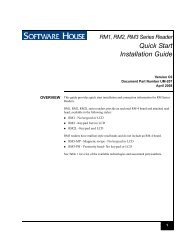
4 Restoring Factory DefaultsThe IPSDU8 has two physical recessed buttons, a Reset button <strong>and</strong> a Restore button. Refer toFigure 4-1 <strong>and</strong> Figure 5-2 for the location of the buttons. These buttons are only used duringinstallation <strong>and</strong> commissioning of the unit <strong>and</strong> during fault finding; they are not intended to be usedduring normal operation when the camera is installed.Both buttons have black caps on them. The Reset button is closer to the I/O board <strong>and</strong> theRestore button is further from the I/O board.NoteThe restore procedure only resets the web configuration pages to default. To reset the SDU8 tofactory defaults, follow the instructions in the SpeedDome ® Ultra 8 Camera Dome Operator’s<strong>Guide</strong>, 8200-0600-01.View of the board with dome removedRestoreButtonResetButtonFigure 4-1 Reset <strong>and</strong> Restore buttonsResetting the IPSDU8The Reset button, when pressed, will restart the IPSDU8.NotePerforming a reset will not change any saved configuration settings.4-1
Restoring Factory DefaultsRestoring factory defaults on the IPSDU8The Restore button must be used in conjunction with the Reset button to restore the IPSDU8 tothe factory defaults.NoteThe restore procedure only resets the web configuration pages to default. To reset the SDU8 tofactory defaults follow the instructions in the SpeedDome ® Ultra 8 Camera Dome Operator’s<strong>Guide</strong>, 8200-0600-01.Procedure 4-1 Restoring the IPSDU8 factory defaultsCautionLoss of configurationRestoring the factory defaults will result in all saved configuration settings being removed <strong>and</strong>the IPSDU8 being restored to the factory settings.1 Ensure that power is being applied to the IPSDU8 from a power supply.2 Press <strong>and</strong> hold the Restore button.3 Press <strong>and</strong> release the Reset button.4 Once the power LED starts flashing rapidly release the Restore button.5 Complete Procedure 3-21 to restore the configuration settings from the last backupconfiguration file.4-2 <strong>Configuration</strong> <strong>and</strong> <strong>User</strong> <strong>Guide</strong>
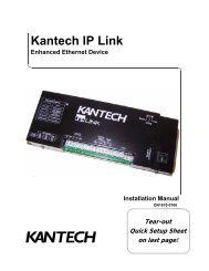
5 Technical SpecificationsThis section details the pin assignments of the serial connectors, <strong>and</strong> the environmental <strong>and</strong>operating specifications of the IPSDU8.IPSDU8 connectorsAlarm input connector (5 way)Alarm output connector (6 way)AC powerconnectorNetwork connector (RJ-45)Figure 5-1 IPSDU8 connectorsLEDs <strong>and</strong> Restore/Reset buttonsRestore ButtonReset ButtonVideo/Alarm LED,yellow(Note)Client LED,orangePower LED, greenView of the board with dome removedNoteFigure 5-2 LEDs <strong>and</strong> Restore <strong>and</strong> Reset buttonsThe Video/Alarm LED is not used in this release except during a firmware or configuration upgradeprocess <strong>and</strong> during the Power On Self Test (POST).5-1
Technical SpecificationsLED Status DescriptionsPower LED• On with repeating slow short flashes off – normal operation• Rapidly flashing – invalid stored configuration/operating on factory defaults.Client LED• On – operating normally with one client connected• Off – operating normally with no clients connected• Flashing rapidly – network not ready, no IP address assigned.Video/Alarm LED• Not used at this release, indicates alarm conditions.NotePower <strong>and</strong> Video/Alarm LEDs rapidly flashing together indicates a firmware or configurationupdate is in progress.NoteDuring the power up process all three LEDs may flash on or off, however if all three LEDs areflashing together followed by a short delay <strong>and</strong> the flash sequence repeated, this indicates aPower On Self Test (POST) error. The number of rapid flashes indicates the actual error code.Contact Technical Support in this instance.5-2 <strong>Configuration</strong> <strong>and</strong> <strong>User</strong> <strong>Guide</strong>
Technical SpecificationsTechnical SpecificationsTable 5-1 Technical SpecificationsCategory Specification DetailsPower Supply voltage 24VACConnector 2.5mmConsumption Combined dome <strong>and</strong> housingIndoor: 36W max (1.5A at 24VAC)Outdoor: 80W max (3.3A at 24VAC)Physical Environment Storage — 23 o F to 140 o F (-5 o C to 60 o C)Operating — 32 o F to 113 o F (0 o C to 45 o C)Humidity 5 - 95% non condensing at 113 o F (45 o C)Altitude Storage <strong>and</strong> operation —- 400ft to 10,000 ft (-122m to 3048m)SizeIndoor hardmountHousing diameter — 190.5mm (7.5in)Housing height above ceiling — 212mm (8.35in)Bubble diameter — 178mm (7.0in)Bubble depth below ceiling — 94mm (3.7in)Weight with SDU8 — 2.5kg (5.5lbs)RHOPN <strong>and</strong> ROENDC Indoor/OutdoorHeight — 32.1cm (12.6in)Diameter — 24.4cm (9.6in)Weight without SDU8 or bubble — 1.42kg (3.13lbs) / 1.635kg (3.6lb)Weight with SDU8 <strong>and</strong> bubble — 3kg (6.61lbs) / 3.215kg (7.09lb)Mechanical connection — 1.66in NPT outside diameterNoteWeights <strong>and</strong> installation heights requirements may vary with thelength of the NPT pipe <strong>and</strong> brackets used.MemoryRAM: 64 MBFlash: 8 MBNetwork Connector RJ-45Protocols http, TCP/IP, DHCP (client)5-3
Technical SpecificationsIPSDU8 Dome AlarmsTable 5-2 Indoor <strong>and</strong> Outdoor alarm detailsInput Alarms(From CableHarness)OutputAlarms(To CableHarness)Quantity <strong>and</strong> Type Name HardwareConnectivity1x TTL Alarm_In_1 To ENCODER only3x TTL Alarm_In_2 to Alarm_In_4 To DOME onlyIndoor3x Open Collector 12V max.100 mA maxOutdoor1x Relay Contact 1A at30VDC or0.3A at 125VACAlarm_Out_1 to Alarm_Out_3From DOME onlyCertification <strong>and</strong> RegulationsTable 5-3 Certification <strong>and</strong> RegulationsCategory Specification DetailsSafety UL/EN/IEC 60950-1 1 st EditionEMC USA FCC Part 15b 107 & 109, class ACanadaICES-003/NMB-003 class AEuropeEN55022:2006 class AEN61000-3-2:2000 + A2:2005EN61000-3-3:1995 + A1:2005 + A2:2005EN50130-4:1995 + A1:1998 + A2:2003Australia /AS/NZS CISPR 22, class ANew Zeal<strong>and</strong>RoHS Complies with European directive 2002/95/EC5-4 <strong>Configuration</strong> <strong>and</strong> <strong>User</strong> <strong>Guide</strong>
6 IndexAAdministrator Front Page 3-4Advanced Features 1-2BBackup configuration 3-21B<strong>and</strong>width Throttling 1-2CCamera Feeds 3-4Canceling configuration changes 3-21Compression 1-1<strong>Configuration</strong> restoring 3-22<strong>Configuration</strong> saving 3-20Connections 1-1FFeatures 1-1Compression 1-1Connections 1-1Frame Rates 1-2Resolution 1-2Firmware upgrading 3-23Frame Rates 1-2Front PageAdministrator 3-4<strong>User</strong> 3-3GGrant of license i-ivIInstallation 2-1LLEDs 5-2LicenseGrant i-ivInformation i-ivSoftware i-ivOOverview 1-1PPatterndefining 3-9definition of 3-9selecting 3-9Pattern <strong>and</strong> Preset Camera Controls 3-9Presetdefining 3-10definition of 3-9selecting 3-10RResolution 1-2SSDU8Focus functions 3-8Iris functions 3-8Pan/Tilt Movement functions 3-8Zoom functions 3-8<strong>Security</strong> configuration 3-12TTCP/IP configuration 3-14UUpgradeFirmware 3-23<strong>User</strong> Front Page 3-3VVideo Input configuration 3-16Video Loss Detection 1-1WWeb <strong>Configuration</strong> 3-1Camera Feeds 3-4Canceling configuration changes 3-21<strong>Configuration</strong> backup 3-21Restoring configuration 3-22Saving configuration 3-20<strong>Security</strong> 3-12TCP/IP 3-14Upgrading Firmware 3-23Video Inputs 3-166-1
Index6-2 <strong>Configuration</strong> <strong>and</strong> <strong>User</strong> <strong>Guide</strong>