
You also want an ePaper? Increase the reach of your titles
YUMPU automatically turns print PDFs into web optimized ePapers that Google loves.
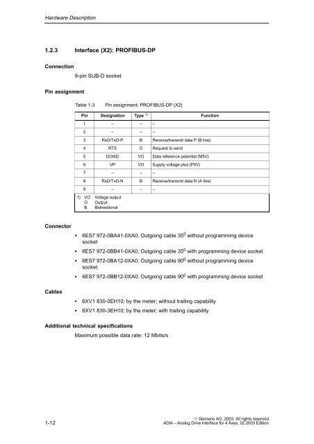
Hardware Description1.2.3 Interface (X2): PROFIBUS-DPConnection9-pin SUB-D socketPin assignmentTable 1-3Pin assignment: PROFIBUS-DP (X2)Pin Designation Type 1) Function1 – – –2 – – –3 RxD/TxD-P B Receive/transmit data P (B line)4 RTS O Request to send5 DGND VO Data reference potential (M5V)6 VP VO Supply voltage plus (P5V)7 – – –8 RxD/TxD-N B Receive/transmit data N (A line)9 – – –1) VO Voltage outputO OutputB BidirectionalConnector6ES7 972-0BA41-0XA0; Outgoing cable 35 0 without programming devicesocket6ES7 972-0BB41-0XA0; Outgoing cable 35 0 with programming device socket6ES7 972-0BA12-0XA0; Outgoing cable 90 0 without programming devicesocket6ES7 972-0BB12-0XA0; Outgoing cable 90 0 with programming device socketCables6XV1 830-0EH10; by the meter; without trailing capability6XV1 830-3EH10; by the meter; with trailing capabilityAdditional technical specificationsMaximum possible data rate: 12 Mbits/s1-12 Siemens AG, <strong>2003</strong>. All rights reserved<strong>ADI4</strong> – Analog Drive Interface for 4 Axes, <strong>02</strong>.<strong>2003</strong> Edition