
Create successful ePaper yourself
Turn your PDF publications into a flip-book with our unique Google optimized e-Paper software.
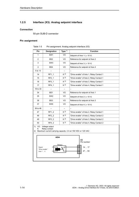
Hardware Description1.2.5 Interface (X3): Analog setpoint interfaceConnection50-pin SUB-D connectorPin assignmentTable 1-5Pin assignment: Analog setpoint interface (X3)Pin Designation Type 1) Function1 SW1 VO Setpoint of Axis 1 (10 V)2 BS2 VO Reference for setpoint of Axis 23 SW3 VO Setpoint of Axis 3 (10 V)4 BS4 VO Reference for setpoint of Axis 45 to 13 – – –14 RF1_1 K 2) “Drive enable” of Axis 1, Relay Contact 115 RF2_1 K 2) “Drive enable” of Axis 2, Relay Contact 116 RF3_1 K 2) “Drive enable” of Axis 3, Relay Contact 117 RF4_1 K 2) “Drive enable” of Axis 4, Relay Contact 118 to 33 – – –34 BS1 VO Reference for setpoint of Axis 135 SW2 VO Setpoint of Axis 2 (10 V)36 BS3 VO Reference for setpoint of Axis 337 SW4 VO Setpoint of Axis 4 (10 V)38 to 46 – – –47 RF1_2 K 2) “Drive enable” of Axis 2, Relay Contact 148 RF2_2 K 2) “Drive enable” of Axis 2, Relay Contact 249 RF3_2 K 2) “Drive enable” of Axis 3, Relay Contact 250 RF4_2 K 2) “Drive enable” of Axis 4, Relay Contact 21) VO Voltage outputK Relay contact2) Maximum current carrying capacity: 2 A at 150 VDC or 125 VACSignal:“Drive enable”Axis 1 ... 4<strong>ADI4</strong>RelaysX3Pin number:14 ... 1747 ... 501-14 Siemens AG, <strong>2003</strong>. All rights reserved<strong>ADI4</strong> – Analog Drive Interface for 4 Axes, <strong>02</strong>.<strong>2003</strong> Edition