
Create successful ePaper yourself
Turn your PDF publications into a flip-book with our unique Google optimized e-Paper software.
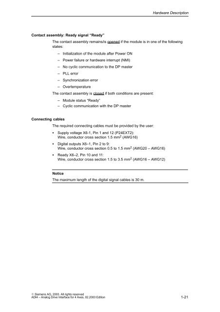
Hardware DescriptionContact assembly: Ready signal “Ready”The contact assembly remains/is opened if the module is in one of the followingstates:– Initialization of the module after Power ON– Power failure or hardware interrupt (NMI)– No cyclic communication to the DP master– PLL error– Synchronization error– OvertemperatureThe contact assembly is closed if both conditions are present:– Module status “Ready”– Cyclic communication with the DP masterConnecting cablesThe required connecting cables must be provided by the user:Supply voltage X6-1, Pin 1 and 12 (P24EXT2):Wire, conductor cross section 1.5 mm 2 (AWG16) Digital outputs X6–1, Pin 2 to 9:Wire, conductor cross section 0.5 to 1.5 mm 2 (AWG20 – AWG16) Ready X6–2, Pin 10 and 11:Wire, conductor cross section 1.5 to 3.5 mm 2 (AWG16 – AWG12)NoticeThe maximum length of the digital signal cables is 30 m. Siemens AG, <strong>2003</strong>. All rights reserved<strong>ADI4</strong> – Analog Drive Interface for 4 Axes, <strong>02</strong>.<strong>2003</strong> Edition1-21