
You also want an ePaper? Increase the reach of your titles
YUMPU automatically turns print PDFs into web optimized ePapers that Google loves.
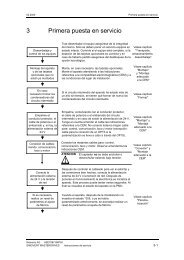
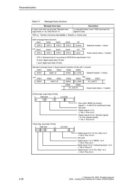
ParameterizationTable 2-1Message frame structureMessage frame type4 axes, each with one encoder, Standard messageframe 3 + IO, PZD-5/9 O/I 1/1PZD x/yNumber of process data words, x: Setpoint, y: Actual valueDescription4 x standard frame 3 and 1 PZD word each fordigital I/O data<strong>ADI4</strong> message frame structureAxis1 Axis2 Axis3Axis4I/OSTD 3STD 3STD 3STD 3Q wordSetpoints (master -> slave)LowAxis1Axis2Axis3Axis4I/OHighSTD 3STD 3STD 3STD 3I wordActual values (slave -> master)STD 3: Standard frame 3 according to PROFIDrive specification V3.0Q word: digital output data (16 bits)I word: digital input data (16 bits)Standard message frame 3: Speed setpoint interface 32 bits with 1 encoderPZD1 PZD2 PZD3 PZD4 PZD5STW1 NSET_BSTW2 G1_STW Setpoint (master –> slave)LowPZD1ZSW1PZD2NACT_BPZD3PZD4ZSW2HighPZD5 PZD6 PZD7G1_ZSW G1_XACT1PZD8PZD9G1_XACT2Actual value (slave –> master)Q Word (dig. output data 16 bits)High byteLow byte15 12 11 8 7 4 3 0I Word (dig. input data 16 bits)High byteLow byte15 14 13 12 11 8 72 1 0Zero mark / BERO as homingsignals 1 – 4 with 611U conformant modeNot usedDigital outputs 1 to 4–> X6–1: Pins 2 to 5Digital outputs 5 to 8 / direction signals1 to 4 for unipolar spindle–> X6–1: Pins 6 to 9Digital inputs 9 to 10 / Drv_Rdy 3 to 4–> X6-2: Pins 10 to11Not usedDigital inputs 1 to 4 / BERO 1 to 4–> X6-2: Pins 2 to 5Digital inputs 5 to 6 / measuring inputs 1 to 2–> X6-2: Pinss 6-7Digital inputs 7 to 8 / Drv_Rdy 1 to 2–> X6-2: Pins 8 to 92-36 Siemens AG, <strong>2003</strong>. All rights reserved<strong>ADI4</strong> – Analog Drive Interface for 4 Axes, <strong>02</strong>.<strong>2003</strong> Edition