
You also want an ePaper? Increase the reach of your titles
YUMPU automatically turns print PDFs into web optimized ePapers that Google loves.
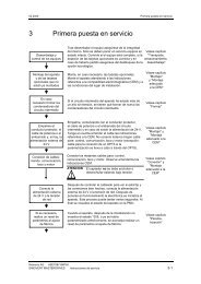
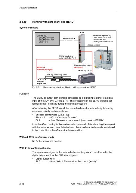
Parameterization2.8.10 Homing with zero mark and BEROSystem structureControl e.g.:– SINUMERIK 8<strong>02</strong>D– SINUMERIK 840Di– SIMOTIONPROFIBUS-DP<strong>ADI4</strong>Converter system e.g.:SIMODRIVE 611 withcontrol unit withanalog setpoint interfaceAnalog setpointDigital inputs e.g.Axis 1: (X6–2), Pin 2BERO oroutput cam signalEncoder actual value /zero markMotor e.g. 1FT6Axis e.g. machining tableBERO oroutput camFig. 2-5Basic system structure: Homing with zero mark and BEROÏÏÏÏÍÍÍÍÍÍÍÍFunctionThe BERO or output cam signal is connected as a digital input signal to a digitalinput of the <strong>ADI4</strong> (X6–2, Pins 2 – 5). The processing of the BERO signal is performedcontrol-internally during the homing procedure.After detecting the BERO signal, the control reduces the axis velocity to homingapproach velocity and requests via: Encoder control word (Gx_STW):Bits 4 – 6: = 001 –> “Activate function”Bit 7: = 1 –> “Reference mark search (zero mark or BERO)”from the <strong>ADI4</strong>, homing to the next encoder zero mark. After detecting the request,with the encoder zero mark detected next, the encoder actual value is transferredto the control from the <strong>ADI4</strong> as the home position.Without 611U conformant modeNo further measures needed.With 611U conformant modeThe appropriate signal for the axis to be homed (e.g. Axis 1) must be set in thedigital output word by the PLC user program: Digital output wordBit 0: = 0 –> “Axis 1: Zero mark of Encoder 1 (X4–1)”2-48 Siemens AG, <strong>2003</strong>. All rights reserved<strong>ADI4</strong> – Analog Drive Interface for 4 Axes, <strong>02</strong>.<strong>2003</strong> Edition