
You also want an ePaper? Increase the reach of your titles
YUMPU automatically turns print PDFs into web optimized ePapers that Google loves.
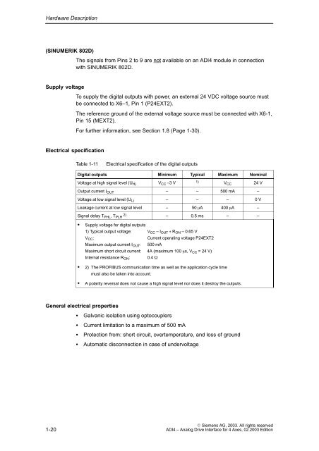
Hardware Description(SINUMERIK 8<strong>02</strong>D)The signals from Pins 2 to 9 are not available on an <strong>ADI4</strong> module in connectionwith SINUMERIK 8<strong>02</strong>D.Supply voltageTo supply the digital outputs with power, an external 24 VDC voltage source mustbe connected to X6–1, Pin 1 (P24EXT2).The reference ground of the external voltage source must be connected with X6-1,Pin 15 (MEXT2).For further information, see Section 1.8 (Page 1-30).Electrical specificationTable 1-11Electrical specification of the digital outputsDigital outputs Minimum Typical Maximum NominalVoltage at high signal level (U H) V CC –3 V 1) V CC 24 VOutput current I OUT – – 500 mA –Voltage at low signal level (U L) – – – 0 VLeakage current at low signal level – 50 A 400 A –Signal delay T PHL , T 2) PLH – 0.5 ms – –Supply voltage for digital outputs1) Typical output voltage: V CC – I OUT R ON – 0.65 VV CC :Current operating voltage P24EXT2Maximum output current I OUT : 500 mAMaximum short circuit current: 4A (maximum 100 s, V CC = 24 V)Internal resistance R ON : 0.4 2) The PROFIBUS communication time as well as the application cycle timemust also be taken into account.A polarity reversal does not cause a high signal level nor does it destroy the outputs.General electrical propertiesGalvanic isolation using optocouplersCurrent limitation to a maximum of 500 mAProtection from: short circuit, overtemperature, and loss of groundAutomatic disconnection in case of undervoltage1-20 Siemens AG, <strong>2003</strong>. All rights reserved<strong>ADI4</strong> – Analog Drive Interface for 4 Axes, <strong>02</strong>.<strong>2003</strong> Edition