
Create successful ePaper yourself
Turn your PDF publications into a flip-book with our unique Google optimized e-Paper software.
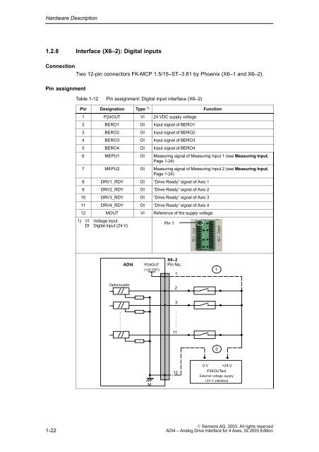
Hardware Description1.2.8 Interface (X6–2): Digital inputsConnectionTwo 12-pin connectors FK-MCP 1.5/15–ST–3.81 by Phoenix (X6–1 and X6–2).Pin assignmentTable 1-12Pin assignment: Digital input interface (X6–2)Pin Designation Type 1) Function1 P24OUT VI 24 VDC supply voltage2 BERO1 DI Input signal of BERO13 BERO2 DI Input signal of BERO24 BERO3 DI Input signal of BERO35 BERO4 DI Input signal of BERO46 MEPU1 DI Measuring signal of Measuring Input 1 (see Measuring Input,Page 1-24)7 MEPU2 DI Measuring signal of Measuring Input 2 (see Measuring Input,Page 1-24)8 DRV1_RDY DI “Drive Ready” signal of Axis 19 DRV2_RDY DI “Drive Ready” signal of Axis 210 DRV3_RDY DI “Drive Ready” signal of Axis 311 DRV4_RDY DI “Drive Ready” signal of Axis 412 MOUT VI Reference of the supply voltage1) VI Voltage inputDI Digital input (24 V)Pin 1<strong>ADI4</strong>P24OUT(+24 VDC)X6–2Pin No.:11Optocoupler23::::::::112M120 V +24 VP24OUTextExternal voltage supply+24 V stabilized1-22 Siemens AG, <strong>2003</strong>. All rights reserved<strong>ADI4</strong> – Analog Drive Interface for 4 Axes, <strong>02</strong>.<strong>2003</strong> Edition