

Gift to
Ii Gift to - Free and Open Source Software
Ii Gift to - Free and Open Source Software
- No tags were found...

Create successful ePaper yourself
Turn your PDF publications into a flip-book with our unique Google optimized e-Paper software.
ed <strong>to</strong> try a hotter tra nsis<strong>to</strong>r<br />
(suc h as the 2N3866), but if<br />
you do you m ay have osci<br />
lla tion p r o b l e m s. At<br />
5/$1.00 from Jam es, t he<br />
2N22 19 does just fi ne!<br />
The output transis<strong>to</strong>r and<br />
co il we re isolated in a sma ll<br />
hal f-box of br ass <strong>to</strong> provide<br />
shie ld ing. A small ho le in<br />
one wa ll passes the ba se<br />
lead wh ich wa s insu lated<br />
w ith a small pi ece of spag<br />
he t t i st r i p p e d fr om<br />
ho oku p w ire . Th e b ase<br />
resis<strong>to</strong>r is gro unded <strong>to</strong> the<br />
outside wa ll, and a shor t<br />
w ire connects <strong>to</strong> the rf ou t<br />
pu t of t he O X oscill a<strong>to</strong> r.<br />
Since the fi nal has f ar more<br />
o utput tha n need ed (it<br />
d raw s 200 mW, as shown],<br />
the output is capacitively<br />
coupled <strong>to</strong> a 47-0hm load<br />
resis<strong>to</strong> r. The <strong>to</strong>p of th e<br />
resis<strong>to</strong>r is connected <strong>to</strong> the<br />
driver output via a va riabl e<br />
capaci<strong>to</strong> r w hich serves as a<br />
drive level control.<br />
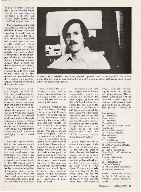
Pho <strong>to</strong> D. Mike WBB/XF, on e o f the original " d ynamic duo" in Lansing A TV. The pa th is<br />
about B mil es, and he was loafing his amplifier along at about 100 Watts peak ou tp ut<br />
when the p ic tu re was taken.<br />
The modul a<strong>to</strong> r is a circu<br />
it designed by WB8JXF.<br />
Th e only modi ficati on invo<br />
lves an adap tation for<br />
use w ith ac-coupled cameras-<br />
fa r mo re co m mo n<br />
than the more expensive deco<br />
u p le d c a m e ras with<br />
w hich the original ci rcuit<br />
wa s used . Modula<strong>to</strong>r lay out<br />
is non-crit ical. The shielded<br />
enclosure and feed through<br />
capaci<strong>to</strong> rs show n in Pho<strong>to</strong><br />
B we re a holdover from<br />
earlier use of the mod ula<strong>to</strong>r<br />
with various 432 transm itter<br />
strips, and such elabo rate<br />
packaging is not requ ired<br />
here.<br />
Tune-up is qu ite simple,<br />
bu t a few regula<strong>to</strong>ry cautio<br />
ns are in order. The<br />
essential point is that we<br />
a re no t a uthor ized t o<br />
broadcast TV signals on<br />
channel 2 or 3, even if the<br />
channel is not in use locally<br />
. The litt le drive r do esn't<br />
put out muc h rf co mpared<br />
<strong>to</strong> the transmitter strip, but<br />
if you connec t it <strong>to</strong> a w ire or<br />
ante nna, it wi ll rad iat e and<br />
that co uld be an invitat ion<br />
<strong>to</strong> trouble. If the uni t is bu ilt<br />
in a shielded box and coax<br />
is used <strong>to</strong> make the interco<br />
nnections, you w ill be<br />
hard pressed <strong>to</strong> pick up the<br />
V H F signal o n the TV in the<br />
shack and yo u w ill not be<br />
rad iat ing the signal.<br />
A grid-dip met er makes<br />
for easy tun e-up , although<br />
it is not essential. If one is<br />
ava ilabl e, switc h th e dipper<br />
<strong>to</strong> the w avem et er mod e<br />
(assumi ng the proper coil is<br />
in place) and co uple the<br />
co il <strong>to</strong> th e OX osci lla<strong>to</strong>r<br />
co il. T un ing around the<br />
proper fr equ ency should<br />
show an rf peak . Tune <strong>to</strong><br />
the pea k and you w ill be on<br />
frequency regardl ess of the<br />
usually poor calibrat ion of<br />
most d ippers (the o ne I used<br />
turned o ut <strong>to</strong> be off by 10<br />
M Hz) . Now sw itch <strong>to</strong> the<br />
d ip mode and co up le <strong>to</strong> the<br />
f inal output co il. With the<br />
lead from th e modula<strong>to</strong> r<br />
disconnected , tun e the coil<br />
for a dip. At this point you<br />
can con nec t the modula<strong>to</strong>r<br />
lead and you sho uld be o n<br />
frequen cy . If yo u sw it ch the<br />
dippe r <strong>to</strong> the wavem et e r<br />
mode, yo u should see a<br />
very substantial rf peak<br />
from th e fi nal.<br />
If no d ipper is av ail ab le,<br />
you ca n proceed as follows.<br />
Tempor aril y remo ve the<br />
co nnection between the<br />
fixed output capac i<strong>to</strong>r and<br />
the 47-0hm load resist or.<br />
Sold er th e free le ad of th e<br />
capaci<strong>to</strong>r <strong>to</strong> the base of a<br />
#49 lamp and gro und th e<br />
shell. D isconne ct the modula<strong>to</strong>r<br />
lead and connec t the<br />
1DO-Ohm resis<strong>to</strong> r <strong>to</strong> 12 V dc<br />
and tune the output coil for<br />
maximu m brilliance on the<br />
l am p . Re co nn ec t t he<br />
capa ci<strong>to</strong> r <strong>to</strong> t he lo ad<br />
resis<strong>to</strong>r and connect the<br />
1DO-O hm resis<strong>to</strong>r back <strong>to</strong><br />
the modul at or output.<br />
Use a piece of coax <strong>to</strong><br />
connect the output of the<br />
dr iver <strong>to</strong> the input of your<br />
TV and tune the latt er <strong>to</strong><br />
the i-f channel. Set the drive<br />
ca pac i<strong>to</strong> r t o minimum<br />
(p lates co m p l e t ely unmeshed)<br />
and turn the driver<br />
on . The TV screen should<br />
go blan k w ith a st ro ng<br />
signal. Connect a properlyadjusted<br />
camera <strong>to</strong> the<br />
video inpu t and run the<br />
came ra inpu t pot throu gh<br />
its range. At one extrem e,<br />
w hite areas w ill begin <strong>to</strong><br />
smear, eve ntually spreading<br />
<strong>to</strong> cover and obscure<br />
any v ideo d isplay. This is<br />
call ed " w hit ing o ut ." At the<br />
other end of the range, the<br />
contrast w ill increase and<br />
yo u wi ll begin <strong>to</strong> lose sync.<br />
The prope r sett i n g is<br />
A1- l 00 Ohm s<br />
A2-1000 Ohms<br />
R3-47 Ohms<br />
A4-100 Ohms<br />
A5- 100 Ohms<br />
R6-10k li nea r-t ap er. panelmounti<br />
ng pot<br />
R7- 47 Ohms, 2 Wa tts<br />
R8- 10 Ohms, 2 Watts<br />
A9- 560 Ohm s<br />
Al0- l 00 Ohm s<br />
All - 2200 Ohms<br />
C1- .001-uF ceramic disc<br />
C2-5·30-pF variable (DAIVE)<br />
value not critical<br />
C3- .001-uF ceramic disc<br />
C4-100-uF , 16.v alum inum<br />
electrolyti c<br />
D1- 9·V, 1-Watt zener<br />
0 1-2N2219<br />
0 2- 1306 (CB dri ver)<br />
0 3-1307 (CB final)<br />
L1-15 turns of #28 ena mel on a<br />
If. inch slug-tuned form<br />
Table 1. Component values<br />
fo r Fig. 1. All resis<strong>to</strong>rs are<br />
1/4 Watt unless o therwise<br />
no ted.<br />
73 Magazine . Oc<strong>to</strong>be r,1980 63


