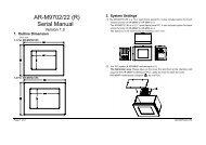
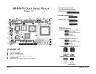
Half Size All-In-One 386SX CPU CARD User’ s Guide
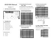
AR-B1375/AR-B1376 Half Size All-In-One 386SX CPU ... - Acrosser
AR-B1375/AR-B1376 Half Size All-In-One 386SX CPU ... - Acrosser
- No tags were found...

You also want an ePaper? Increase the reach of your titles
YUMPU automatically turns print PDFs into web optimized ePapers that Google loves.
AR-B1375/AR-B1376 Users <strong>Guide</strong><br />
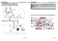
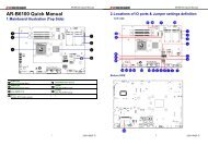
3.2 SYSTEM SETTING<br />
Jumper pins allow you to set specific system parameters. Set them by changing the pin location of jumper blocks.<br />
(A jumper block is a small plastic-encased conductor [shorting plug] that slips over the pins.) To change a jumper<br />
setting, remove the jumper from its current location with your fingers or small needle-nosed pliers. Place the<br />
jumper over the two pins designated for the desired setting. Press the jumper evenly onto the pins. Be careful not<br />
to bend the pins.<br />
We will show the locations of the AR-B1375 and AR-B1376 jumper pins, and the factory-default setting.<br />
CAUTION: Do not touch any electronic component unless you are safely grounded. Wear a grounded wrist strap<br />
or touch an exposed metal part of the system unit chassis. The static discharges from your fingers can<br />
permanently damage electronic components.<br />
3.2.1 Keyboard Connector<br />
(1) 6-Pin Mini DIN Keyboard Connector (CN3)<br />
CN3 is a Mini-DIN 6-pin connector. This keyboard connector is PS/2 type keyboard connector. This connector is<br />
also for a standard IBM-compatible keyboard with the keyboard adapter cable.<br />
CN3<br />
1 DATA<br />
2 N.C.<br />
3 GND<br />
4 VCC<br />
5 CLOCK<br />
6 N.C.<br />
1 2<br />
3 4<br />
5 6<br />
Front View<br />
Figure 3-2 CN3: 6-Pin Mini Din Keyboard Connector<br />
(2) AUX. Keyboard Connector (J4)<br />
We can use a PC/AT compatible keyboard to connecting the provided adapter cable between J4 and the keyboard.<br />
The pin assignments of J4 connector are as follows:<br />
1 CLOCK<br />
2 DATA<br />
3 N.C.<br />
4 GND<br />
5 VCC<br />
J4<br />
Figure 3-3 J4: AUX. Keyboard Connector<br />
3-2