Half Size All-In-One 386SX CPU CARD User’ s Guide
AR-B1375/AR-B1376 Half Size All-In-One 386SX CPU ... - Acrosser
AR-B1375/AR-B1376 Half Size All-In-One 386SX CPU ... - Acrosser
- No tags were found...

Create successful ePaper yourself
Turn your PDF publications into a flip-book with our unique Google optimized e-Paper software.
AR-B1375/AR-B1376 Users <strong>Guide</strong><br />
(3) Typing DOS Command<br />
You can use another way to format and copy files to the 5V FLASH EPROM. This method provides the<br />
convenience of using a RAM disk. You can use the DOS and command to format and copy<br />
files. Follow the following steps to format and copy files to the FLASH disk. it is the same procedure as step 1 to<br />
step 4 of using the UV EPROM.<br />
Step 1: Turn on your computer, when the screen shows the SSD BIOS menu, please hit the [F1] key during the<br />
system boot-up, this enables you to enter the FLASH setup program. If the program does not show up,<br />
check the switch setting of SW1.<br />
Step 2: Use , , , and arrow keys to select the correct FLASH memory<br />
type and how many memory chips are going to be used.<br />
Step 3: Press the [F4] key to save the current settings.<br />
Step 4: After the DOS is loaded, use the DOS [FORMAT] command to format the FLASH disk.<br />
To format the disk and copy DOS system files to the disk.<br />
C:\>FORMAT [ROM disk letter] /S /U<br />
To format the disk without copying DOS system files.<br />
C:\>FORMAT [ROM disk letter] /U<br />
Step 5: Copy your program or files to the FLASH disk by using DOS [COPY] command.<br />
CAUTION: It is not recommended that the user formatted the disk and copy files to the FLASH disk very often.<br />
Since the FLASH EPROM’s write cycle life time is about 10,000 or 100,000 times, writing data to the<br />
FLASH too often will reduce the life time of the FLASH EPROM chips, especially the FLASH EPROM<br />
chip in the MEM1 socket.<br />
6.4.4 RAM Disk<br />
(1) Switch and Jumper Setting<br />
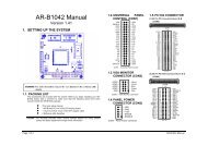
Step 1: Use jumper block to set the memory type as ROM (FLASH).<br />
Step 2: Select the proper I/O base port, firmware address, disk drive number on SW1.<br />
Step 3: <strong>In</strong>sert programmed SRAM chips into sockets starting at MEM1.<br />
NOTE: If you use the SRAM, please skip the SW1-5 & SW1-6 setting.<br />
A B C<br />
JP4<br />
1<br />
2<br />
1 2 3<br />
3<br />
SRAM<br />
M1~M3<br />
Figure 6-10 SRAM Jumper Setting<br />
6-10