Half Size All-In-One 386SX CPU CARD User’ s Guide
AR-B1375/AR-B1376 Half Size All-In-One 386SX CPU ... - Acrosser
AR-B1375/AR-B1376 Half Size All-In-One 386SX CPU ... - Acrosser
- No tags were found...

You also want an ePaper? Increase the reach of your titles
YUMPU automatically turns print PDFs into web optimized ePapers that Google loves.
AR-B1375/AR-B1376 Users <strong>Guide</strong><br />
2. SYSTEM CONTROLLER<br />
This chapter describes the major structure of the AR-B1375 and AR-B1376 <strong>CPU</strong> board. The following topics are<br />
covered:<br />
• Microprocessor<br />
• DMA Controller<br />
• Keyboard Controller<br />
• <strong>In</strong>terrupt Controller<br />
• Real-Time Clock and Non-Volatile RAM<br />
• Timer<br />
• Serial Port<br />
• Parallel Port<br />
2.1 MICROPROCESSOR<br />
The AR-B1375 and AR-B1376 use the ALI M6117 <strong>CPU</strong>, it is designed to perform like <strong>In</strong>tel’s <strong>386SX</strong> system with<br />
deep green features.<br />
The <strong>386SX</strong> core is the same as M1<strong>386SX</strong> of Acer Labs. <strong>In</strong>c. and 100% object code compatible with the <strong>In</strong>tel<br />
<strong>386SX</strong> microprocessor. System manufacturers can provide 386 <strong>CPU</strong> based systems optimized for both cost and<br />
size. <strong>In</strong>struction pipelining and high bus bandwidth ensure short average instruction execution times and high<br />
system throughput. Furthermore, it can keep the state internally from charge leakage while external clock to the<br />
core is stopped without storing the data in registers. The power consumption here is almost zero when clock stops.<br />
The internal structure of this core is 32-bit data and address bus with very low supply current. Real mode as well<br />
as Protected mode are available and can run MS-DOS, MS-Windows, OS/2 and UNIX.<br />
2.2 DMA CONTROLLER<br />
The equivalent of two 8237A DMA controllers are implemented in the AR-B1375/AR-B1376 board. Each controller<br />
is a four-channel DMA device that will generate the memory addresses and control signals necessary to transfer<br />
information directly between a peripheral device and memory. This allows high speeding information transfer with less<br />
<strong>CPU</strong> intervention. The two DMA controllers are internally cascaded to provide four DMA channels for transfers to<br />
8-bit peripherals (DMA1) and three channels for transfers to 16-bit peripherals (DMA2). DMA2 channel 0 provides<br />
the cascade interconnection between the two DMA devices, thereby maintaining IBM PC/AT compatibility.<br />
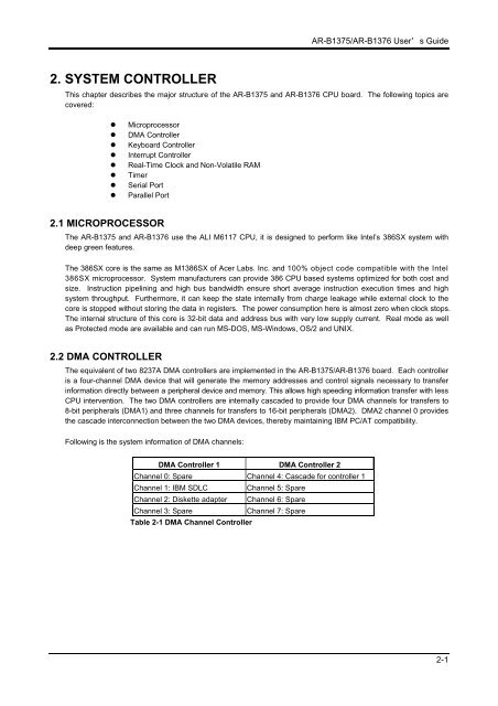
Following is the system information of DMA channels:<br />
DMA Controller 1 DMA Controller 2<br />
Channel 0: Spare Channel 4: Cascade for controller 1<br />
Channel 1: IBM SDLC<br />
Channel 5: Spare<br />
Channel 2: Diskette adapter Channel 6: Spare<br />
Channel 3: Spare<br />
Channel 7: Spare<br />
Table 2-1 DMA Channel Controller<br />
2-1