Half Size All-In-One 386SX CPU CARD User’ s Guide
AR-B1375/AR-B1376 Half Size All-In-One 386SX CPU ... - Acrosser
AR-B1375/AR-B1376 Half Size All-In-One 386SX CPU ... - Acrosser
- No tags were found...

You also want an ePaper? Increase the reach of your titles
YUMPU automatically turns print PDFs into web optimized ePapers that Google loves.
AR-B1375/AR-B1376 Users <strong>Guide</strong><br />
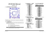
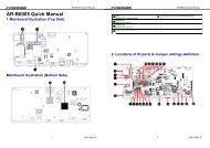
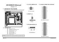
(5) RS-232 Connector (CN7 & DB2)<br />
There are two serial ports with EIA RS-232 interface on the AR-B1375 or AR-B1376. COM A uses one on-board<br />
D-type 9-pin male connector (DB2) which is located at the right side of the card, and COM B uses one 10-pin<br />
header (CN7) which is located at the upper of the card. To configure these two serial ports, use the BIOS Setup<br />
program to do well, and adjust the jumpers on J6 and J7.<br />
The pin assignments of the DB2 and CN7 for serial port A & B are as follows:<br />
DB2 (COM A)<br />
CN7 (COM B)<br />
GND 5<br />
1<br />
9-RI<br />
-DTR 4<br />
2<br />
8-CTS<br />
TXD 3<br />
7-RTS<br />
RXD 2<br />
6-DSR<br />
-DCD 1<br />
Figure 3-15 CN7 & DB2: RS-232 Connector<br />
CN7 DB2 Signal CN7 DB2 Signal<br />
1 1 -DCD 2 6 -DSR<br />
3 2 RXD 4 7 -RTS<br />
5 3 TXD 6 8 -CTS<br />
7 4 -DTR 8 9 -RI<br />
9 5 GND 10 -- Not Used<br />
Table 3-2 Serial Port Pin Assignment<br />
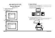
3.2.7 Reset Header (J1)<br />
J1 is used to connect to an external reset switch. Shorting these two pins will reset the system.<br />
1 Reset+<br />
2 Reset-<br />
Figure 3-16 J1: Reset Header<br />
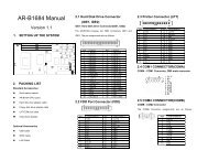
3.2.8 LED Header<br />
(1) External Power LED Header (J2)<br />
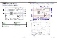
(2) HDD LED Header (J8)<br />
1 2 3<br />
1 Power LED+<br />
2 No Connect<br />
3 Power LED-<br />
Figure 3-17 J2: External Power LED Header<br />
1 LED+<br />
2 LED-<br />
Figure 3-18 J8: HDD LED Header<br />
3-8