You also want an ePaper? Increase the reach of your titles
YUMPU automatically turns print PDFs into web optimized ePapers that Google loves.
To satisfy the requirement for strength limit state design the following relationship must be satisfied:<br />
M * < φM s<br />
The maximum design bending moment is therefore equal to the design section moment capacity (M * <<br />
φM s ), and the maximum design load is that design load (W * L ) which corresponds to the maximum<br />
design bending moment. It should be noted that in this instance the bending capacity of the beam may not<br />
be the only criteria in the strength limit state which needs to be considered. (eg. shear capacity, bearing<br />
capacity).<br />
The DCTDHS gives values of design capacity (φR u ) and maximum design load (W *), where applicable,<br />
determined in accordance with AS 4100. When using these tables, the designer must determine the<br />
relevant strength limit state design action (W *) and/or the corresponding design action effects (S *) to<br />
ensure the strength limit state requirements of AS 4100 are satisfied. Other limit states (e.g. serviceability,<br />
fatigue) must also be considered by the designer. Section 8 of the tables contains design aids for checking<br />
the serviceability limit state for some specific beam load and support configurations.<br />
GENERAL NOTES ON THE TABLES<br />
CONTENTS AND USAGE<br />
For the commonly available Australian structural steel hollow <strong>sections</strong>, tables are provided for:<br />
(i)<br />
(ii)<br />
section dimensions and section properties, i.e:<br />
- Dimensions and Properties (PART 1)<br />
- Surface Areas (PART 1)<br />
- Properties for Assessing Section Capacity to AS 4100 (PART 1)<br />
- Properties for Fire Design (PART 1)<br />
- Telescoping Sections (PART 1)<br />
design capacity (φR u ) for:<br />
- Section Capacities (PART 3)<br />
- Members Subject to Bending (PART 4)<br />
- Members Subject to Axial Compression (PART 5)<br />
- Members Subject to Axial Tension (PART 6)<br />
(iii) elastic buckling load (N om ) (PART 7)<br />
(iv) maximum design load (W *) for:<br />
- Strength Limit State (W * L ) for Beams (PART 8)<br />
- Serviceability Limit State (W * S ) for Beams (PART 8)<br />
(simply supported, continuous, fixed end and cantilever beams)<br />
Acceptable methods of analysis for determining the design action effects are described in Section 4 of<br />
AS 4100 and PART 2 of this publication. Information relevant to such methods of analysis is presented<br />
briefly in PART 7 of this publication.<br />
The above recommendations apply to predominantly statically loaded structures but also in broad principle<br />
to dynamically loaded structures subject to moderate cyclic loads, as specified in AS 4100 Section 1, Fatigue.<br />
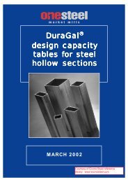
DuraGal DESIGN CAPACITY TABLES<br />
DCTDHS/06<br />
xii for STRUCTURAL STEEL HOLLOW SECTIONS MARCH 2002


