
You also want an ePaper? Increase the reach of your titles
YUMPU automatically turns print PDFs into web optimized ePapers that Google loves.
D4.1.3<br />
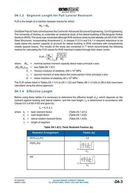
Segment Length for Full Lateral Restraint<br />
FLR is the length of a member between braces for which:<br />
M bx = M sx<br />
OneSteel Pipe & Tube commissioned the Centre for Advanced Structural Engineering, Civil Engineering,<br />
The University of Sydney, to undertake an analytical study of the lateral buckling of Rectangular Hollow<br />
Sections (RHS). The study was conducted although RHS <strong>sections</strong> rarely buckle laterally, yet AS 4100-1990<br />
Steel Structures, incorporating Amendment 2, in clauses 5.3.2.4 and 5.6.1.4 required reductions to be<br />
made below the section capacity to account for lateral buckling in RHS members with comparatively<br />
closely spaced braces. The results of the study are contained in [1] which recommends the following<br />
method for calculating the FLR values for RHS members loaded through their shear centre.<br />
FLR<br />
F sx<br />
=<br />
H G M I<br />
Myz<br />
K J<br />
FLR<br />
π 2 y<br />
2<br />
Msx<br />
El GJ<br />
where M sx = nominal section moment capacity about major principal x-axis<br />
(M sx /M yz ) FLR = see Table D4.1.5(1)<br />
E = Young’s modulus of elasticity, 200 x 10 3 MPa<br />
I y = second moment of area about the cross-section minor principal y-axis<br />
G = shear modulus of elasticity, 80 x 10 3 MPa<br />
The FLR values listed in Tables D4.1-1(1) to D4.1-1(2) and Tables D8.1-1(1)(A) to D8.4-4(A) have been<br />
calculated using the above approach.<br />
D4.1.4<br />
Effective Length<br />
Before using these tables it is necessary to determine the effective length (L e ), which depends on the<br />
restraint against twisting and lateral rotation, and the load height. L e is determined in accordance with<br />
Clause 5.6.3 of AS 4100 and given by:<br />
L e = k t k l k r L<br />
where k t = twist restraint factor (Table D4.1.4(1))<br />
k l = load height factor (Table D4.1.4(2))<br />
k r = lateral rotation restraint factor (Table D4.1.4(3))<br />
L = length of segment<br />
Table D4.1.4(1): Twist Restraint Factors (k t )<br />
Restraint Arrangement Factor, (k t )<br />
FF,FL,LL,FU 1.0<br />
FP,PL,PU<br />
PP<br />
1+<br />
1+<br />
L<br />
F<br />
NM<br />
1I HG K J F d<br />
H G L<br />
n<br />
tf<br />
2t<br />
w<br />
L F 1I 2HG K J F d<br />
NM<br />
H G L<br />
n<br />
w<br />
tf<br />
2t<br />
w<br />
I K J<br />
w<br />
3<br />
I K J<br />
O<br />
QP<br />
3<br />
O<br />
QP<br />
DCTDHS/06<br />
DuraGal DESIGN CAPACITY TABLES<br />
MARCH 2002 for STRUCTURAL STEEL HOLLOW SECTIONS D4-3