
Create successful ePaper yourself
Turn your PDF publications into a flip-book with our unique Google optimized e-Paper software.
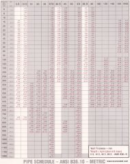
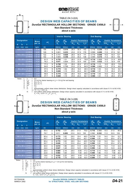
TABLE D4.3-2(A)<br />
DESIGN WEB CAPACITIES OF BEAMS<br />
DuraGal RECTANGULAR HOLLOW SECTIONS: GRADE C450L0<br />
Non-Standard Thickness<br />
about x-axis<br />
Interior Bearing<br />
End Bearing<br />
Designation<br />
d b t<br />
φR<br />
Mass<br />
by<br />
φR bb<br />
Useful Parameters φR by<br />
φR bb<br />
Useful Parameters<br />
φV<br />
per m v<br />
b b<br />
b b<br />
5r ext<br />
b bw<br />
L e<br />
/r b b<br />
b b<br />
2.5r ext<br />
b bw<br />
L e<br />
/r<br />
mm mm mm kg/m kN kN/mm kN/mm mm mm mm kN/mm kN/mm mm mm mm<br />
125 x 75 x 2.8 RHS 8.39 156 N 0.735 0.414 28.0 56.9 142 0.718 0.359 14.0 56.9 154<br />
2.3 RHS 6.95 129 N 0.601 0.233 23.0 57.9 176 0.590 0.200 11.5 57.9 191<br />
100 x 50 x 2.8 RHS 6.19 122 N 0.741 0.626 28.0 44.4 111 0.718 0.548 14.0 44.4 121<br />
2.3 RHS 5.14 102 N 0.605 0.358 23.0 45.4 138 0.590 0.310 11.5 45.4 150<br />
75 x 50 x 2.8 RHS 5.09 91.4 N 0.752 1.01 28.0 31.9 79.8 0.718 0.908 14.0 31.9 86.6<br />
2.3 RHS 4.24 76.2 N 0.611 0.604 23.0 32.9 100 0.590 0.532 11.5 32.9 109<br />
65 x 35 x 2.8 RHS 3.99 77.3 N 0.758 1.24 28.0 26.9 67.3 0.718 1.13 14.0 26.9 73.0<br />
2.3 RHS 3.34 64.6 N 0.616 0.766 23.0 27.9 84.9 0.590 0.683 11.5 27.9 92.2<br />
50 x 25 x 2.8 RHS 2.89 57.5 N 0.775 1.62 28.0 19.4 48.5 0.718 1.53 14.0 19.4 52.7<br />
2.3 RHS 2.44 48.3 N 0.626 1.10 23.0 20.4 62.1 0.590 1.01 11.5 20.4 67.4<br />
50 x 20 x 2.8 RHS 2.67 56.8 N 0.775 1.62 28.0 19.4 48.5 0.718 1.53 14.0 19.4 52.7<br />
2.3 RHS 2.25 47.7 N 0.626 1.10 23.0 20.4 62.1 0.590 1.01 11.5 20.4 67.4<br />
Notes : 1. φ = 0.9<br />
2. L e<br />
/r = 3.5 d 5<br />
/t for interior bearing or L e<br />
/r = 3.8 d 5<br />
/t for end bearing<br />
3. φR by<br />
= 2φ α p<br />
b b<br />
t f y<br />
4. φR bb<br />
= 2φ α c<br />
b b<br />
t f y<br />
5. αb = 0.5<br />
6. k f<br />
= 1.0<br />
7. U = approximately uniform shear stress distribution. Design shear capacity calculated in accordance with clause 5.11.4 of AS 4100.<br />
V v<br />
= V u<br />
= V w<br />
= 0.6 f y<br />
A w<br />
N = non-uniform shear stress distribution. Design shear capacity calculated in accordance with clause 5.11.3 of AS 4100.<br />
V v<br />
= 2V u<br />
/ (0.9 + (f * vm<br />
/f * va<br />
)) ≤ V u<br />
TABLE D4.3-2(B)<br />
DESIGN WEB CAPACITIES OF BEAMS<br />
DuraGal RECTANGULAR HOLLOW SECTIONS: GRADE C450L0<br />
Non-Standard Thickness<br />
about y-axis<br />
Interior Bearing<br />
End Bearing<br />
Designation<br />
φR<br />
Mass<br />
by<br />
φR bb<br />
Useful Parameters φR by<br />
φR bb<br />
Useful Parameters<br />
φV<br />
per m v<br />
b<br />
d b t<br />
b<br />
b b<br />
5r ext<br />
b bw<br />
L e<br />
/r b b<br />
b b<br />
2.5r ext<br />
b bw<br />
L e<br />
/r<br />
mm mm mm kg/m kN kN/mm kN/mm mm mm mm kN/mm kN/mm mm mm mm<br />
125 x 75 x 2.8 RHS 8.39 94.4 U 0.752 1.01 28.0 31.9 79.8 0.718 0.908 14.0 31.9 86.6<br />
2.3 RHS 6.95 78.7 U 0.611 0.609 23.0 32.9 100 0.590 0.532 11.5 32.9 109<br />
100 x 50 x 2.8 RHS 6.19 60.4 U 0.775 1.62 28.0 19.4 48.5 0.718 1.53 14.0 19.4 52.7<br />
2.3 RHS 5.14 50.7 U 0.626 1.10 23.0 20.4 62.1 0.590 1.01 11.5 20.4 67.4<br />
75 x 50 x 2.8 RHS 5.09 60.4 U 0.775 1.62 28.0 19.4 48.5 0.718 1.53 14.0 19.4 52.7<br />
2.3 RHS 4.24 50.7 U 0.626 1.10 23.0 20.4 62.1 0.590 1.01 11.5 20.4 67.4<br />
65 x 35 x 2.8 RHS 3.99 40.0 U 0.810 1.96 28.0 11.9 29.8 0.718 1.92 14.0 11.9 32.3<br />
2.3 RHS 3.34 34.0 U 0.647 1.48 23.0 12.9 39.3 0.590 1.42 11.5 12.9 42.6<br />
50 x 25 x 2.8 RHS 2.89 26.4 U 0.869 2.16 28.0 6.90 17.3 0.718 2.14 14.0 6.90 18.7<br />
2.3 RHS 2.44 22.8 U 0.682 1.69 23.0 7.90 24.0 0.590 1.66 11.5 7.90 26.1<br />
50 x 20 x 2.8 RHS 2.67 19.6 U 0.932 2.25 28.0 4.40 11.0 0.718 2.24 14.0 4.40 11.9<br />
2.3 RHS 2.25 17.2 U 0.719 1.78 23.0 5.40 16.4 0.590 1.77 11.5 5.40 17.8<br />
Notes : 1. φ = 0.9<br />
2. L e<br />
/r = 3.5 d 5<br />
/t for interior bearing or L e<br />
/r = 3.8 d 5<br />
/t for end bearing<br />
3. φR by<br />
= 2φ α p<br />
b b<br />
t f y<br />
4. φR bb<br />
= 2φ α c<br />
b b<br />
t f y<br />
5. αb = 0.5<br />
6. k f<br />
= 1.0<br />
7. U = approximately uniform shear stress distribution. Design shear capacity calculated in accordance with clause 5.11.4 of AS 4100.<br />
V v<br />
= V u<br />
= V w<br />
= 0.6 f y<br />
A w<br />
N = non-uniform shear stress distribution. Design shear capacity calculated in accordance with clause 5.11.3 of AS 4100.<br />
V v<br />
= 2V u<br />
/ (0.9 + (f * vm<br />
/f * va<br />
)) ≤ V u<br />
DCTDHS/06<br />
DuraGal DESIGN CAPACITY TABLES<br />
MARCH 2002 for STRUCTURAL STEEL HOLLOW SECTIONS D4-21