
You also want an ePaper? Increase the reach of your titles
YUMPU automatically turns print PDFs into web optimized ePapers that Google loves.
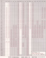
DuraGal DESIGN CAPACITY TABLES DCTDHS/06<br />
D4-18 for STRUCTURAL STEEL HOLLOW SECTIONS MARCH 2002<br />
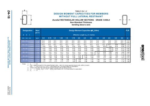
TABLE D4.1-2<br />
DESIGN MOMENT CAPACITIES FOR MEMBERS<br />
WITHOUT FULL LATERAL RESTRAINT<br />
DuraGal RECTANGULAR HOLLOW SECTIONS: GRADE C450L0<br />
Non-Standard Thickness<br />
bending about x-axis<br />
Designation Mass Design Moment Capacities φM b<br />
(kNm) FLR<br />
per m<br />
d b t<br />
Effective Length (L e ) in metres<br />
mm mm mm kg/m 0.5 0.75 1.0 1.25 1.5 1.75 2.0 2.5 3.0 3.5 4.0 4.5 5.0 6.0 m<br />
125 x 75 x 2.8 RHS 8.39 16.9 16.9 16.9 16.9 16.9 16.9 16.9 16.9 16.9 16.9 16.9 16.9 16.9 16.9 7.51<br />
2.3 RHS 6.95 12.3 12.3 12.3 12.3 12.3 12.3 12.3 12.3 12.3 12.3 12.3 12.3 12.3 12.3 8.69<br />
100 x 50 x 2.8 RHS 6.19 10.2 10.2 10.2 10.2 10.2 10.2 10.2 10.2 10.2 10.2 10.2 10.1 9.94 9.63 4.34<br />
2.3 RHS 5.14 8.52 8.52 8.52 8.52 8.52 8.52 8.52 8.52 8.52 8.52 8.52 8.48 8.34 8.08 4.37<br />
75 x 50 x 2.8 RHS 5.09 6.52 6.52 6.52 6.52 6.52 6.52 6.52 6.52 6.52 6.52 6.52 6.52 6.49 6.31 4.85<br />
2.3 RHS 4.24 5.49 5.49 5.49 5.49 5.49 5.49 5.49 5.49 5.49 5.49 5.49 5.49 5.47 5.32 4.88<br />
65 x 35 x 2.8 RHS 3.99 4.21 4.21 4.21 4.21 4.21 4.21 4.21 4.21 4.21 4.13 4.04 3.95 3.86 3.69 3.08<br />
2.3 RHS 3.34 3.57 3.57 3.57 3.57 3.57 3.57 3.57 3.57 3.57 3.50 3.43 3.35 3.28 3.14 3.11<br />
50 x 25 x 2.8 RHS 2.89 2.26 2.26 2.26 2.26 2.26 2.26 2.26 2.19 2.12 2.05 1.99 1.92 1.86 1.75 2.08<br />
2.3 RHS 2.44 1.94 1.94 1.94 1.94 1.94 1.94 1.94 1.89 1.83 1.77 1.71 1.66 1.61 1.51 2.11<br />
50 x 20 x 2.8 RHS 2.67 1.99 1.99 1.99 1.99 1.98 1.93 1.89 1.80 1.72 1.64 1.57 1.50 1.43 1.31 1.45<br />
2.3 RHS 2.25 1.71 1.71 1.71 1.71 1.71 1.67 1.63 1.56 1.49 1.42 1.36 1.30 1.25 1.15 1.48<br />
Notes: 1. φ = 0.9<br />
2. FLR - segment length for Full Lateral Restraint (φM bx<br />
= φM sx<br />
) for simply supported beams with uniform moment.<br />
FLR = 0.231 (π 2 E /y G J / M sx2<br />
) 0.5 (See Section D4.1.3 of these tables for explanation)<br />
3. Values to the left of the solid line are segment lengths with full lateral restraint.<br />
4. α sh<br />
= 0.7(((M sx<br />
/ M oa<br />
) 2 + 2.7)) 0.5 - M s<br />
/M oa<br />
) (See Section D4.1.2 of these tables for explanation)<br />
5. α m<br />
= 1.0