Create successful ePaper yourself
Turn your PDF publications into a flip-book with our unique Google optimized e-Paper software.
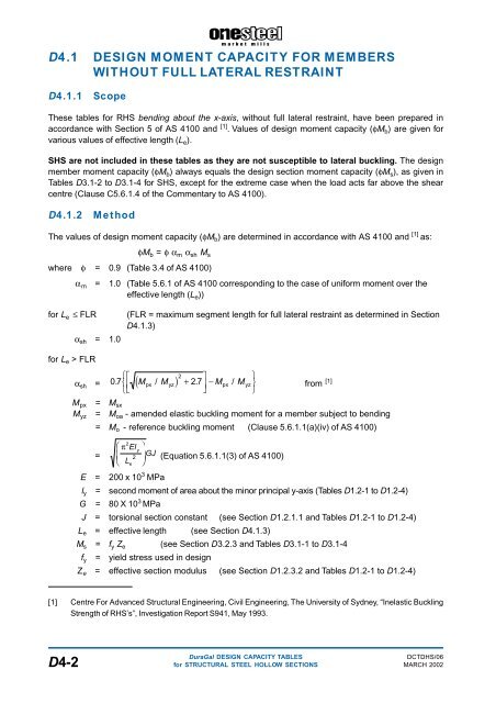
D4.1 DESIGN MOMENT CAPACITY FOR MEMBERS<br />
WITHOUT FULL LATERAL RESTRAINT<br />
D4.1.1<br />
Scope<br />
These tables for RHS bending about the x-axis, without full lateral restraint, have been prepared in<br />
accordance with Section 5 of AS 4100 and [1] . Values of design moment capacity (φM b ) are given for<br />
various values of effective length (L e ).<br />
SHS are not included in these tables as they are not susceptible to lateral buckling. The design<br />
member moment capacity (φM b ) always equals the design section moment capacity (φM s ), as given in<br />
Tables D3.1-2 to D3.1-4 for SHS, except for the extreme case when the load acts far above the shear<br />
centre (Clause C5.6.1.4 of the Commentary to AS 4100).<br />
D4.1.2<br />
Method<br />
The values of design moment capacity (φM b ) are determined in accordance with AS 4100 and [1] as:<br />
φM b = φ α m α sh M s<br />
where φ = 0.9 (Table 3.4 of AS 4100)<br />
α m = 1.0 (Table 5.6.1 of AS 4100 corresponding to the case of uniform moment over the<br />
effective length (L e ))<br />
for L e £ FLR<br />
α sh = 1.0<br />
(FLR = maximum segment length for full lateral restraint as determined in Section<br />
D4.1.3)<br />
for L e > FLR<br />
R<br />
SL<br />
TNM<br />
O<br />
QP −<br />
2<br />
d px yzh +<br />
px yz<br />
α sh = 07 . M / M 27 . M / M<br />
U<br />
V<br />
W<br />
from [1]<br />
M px = M sx<br />
M yz = M oa - amended elastic buckling moment for a member subject to bending<br />
= M o - reference buckling moment (Clause 5.6.1.1(a)(iv) of AS 4100)<br />
F<br />
HG<br />
π 2 Ely<br />
2<br />
Le<br />
I<br />
=<br />
GJ<br />
KJ (Equation 5.6.1.1(3) of AS 4100)<br />
E = 200 x 10 3 MPa<br />
l y = second moment of area about the minor principal y-axis (Tables D1.2-1 to D1.2-4)<br />
G = 80 X 10 3 MPa<br />
J = torsional section constant (see Section D1.2.1.1 and Tables D1.2-1 to D1.2-4)<br />
L e = effective length (see Section D4.1.3)<br />
M s = f y Z e (see Section D3.2.3 and Tables D3.1-1 to D3.1-4<br />
f y = yield stress used in design<br />
Z e = effective section modulus (see Section D1.2.3.2 and Tables D1.2-1 to D1.2-4)<br />
[1] Centre For Advanced Structural Engineering, Civil Engineering, The University of Sydney, “Inelastic Buckling<br />
Strength of RHS’s”, Investigation Report S941, May 1993.<br />
DuraGal DESIGN CAPACITY TABLES<br />
DCTDHS/06<br />
D4-2 for STRUCTURAL STEEL HOLLOW SECTIONS MARCH 2002


