
Create successful ePaper yourself
Turn your PDF publications into a flip-book with our unique Google optimized e-Paper software.
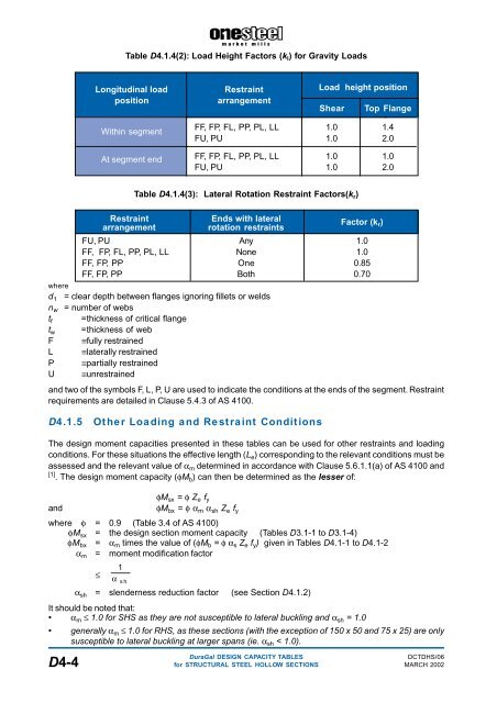
Table D4.1.4(2): Load Height Factors (k l ) for Gravity Loads<br />
Longitudinal load Restraint Load height position<br />
position<br />
arrangement<br />
Shear Top Flange<br />
Within segment<br />
FF, FP, FL, PP, PL, LL 1.0 1.4<br />
FU, PU 1.0 2.0<br />
At segment end FF, FP, FL, PP, PL, LL 1.0 1.0<br />
FU, PU 1.0 2.0<br />
Table D4.1.4(3): Lateral Rotation Restraint Factors(k r )<br />
Restraint Ends with lateral<br />
arrangement<br />
rotation restraints<br />
Factor (k r )<br />
FU, PU Any 1.0<br />
FF, FP, FL, PP, PL, LL None 1.0<br />
FF, FP, PP One 0.85<br />
FF, FP, PP Both 0.70<br />
where<br />
d 1 = clear depth between flanges ignoring fillets or welds<br />
n w = number of webs<br />
t f =thickness of critical flange<br />
t w =thickness of web<br />
F ≡fully restrained<br />
L ≡laterally restrained<br />
P ≡partially restrained<br />
U ≡unrestrained<br />
and two of the symbols F, L, P, U are used to indicate the conditions at the ends of the segment. Restraint<br />
requirements are detailed in Clause 5.4.3 of AS 4100.<br />
D4.1.5<br />
Other Loading and Restraint Conditions<br />
The design moment capacities presented in these tables can be used for other restraints and loading<br />
conditions. For these situations the effective length (L e ) corresponding to the relevant conditions must be<br />
assessed and the relevant value of α m determined in accordance with Clause 5.6.1.1(a) of AS 4100 and<br />
[1] . The design moment capacity (φM b ) can then be determined as the lesser of:<br />
and<br />
φM sx = φ Z e f y<br />
φM bx = φ α m α sh Z e f y<br />
where φ = 0.9 (Table 3.4 of AS 4100)<br />
φM sx = the design section moment capacity (Tables D3.1-1 to D3.1-4)<br />
φM bx = α m times the value of (φM b = φ α s Z e f y ) given in Tables D4.1-1 to D4.1-2<br />
α m = moment modification factor<br />
1<br />
≤<br />
α sh<br />
α sh = slenderness reduction factor (see Section D4.1.2)<br />
It should be noted that:<br />
• α m ≤ 1.0 for SHS as they are not susceptible to lateral buckling and α sh = 1.0<br />
• generally α m ≤ 1.0 for RHS, as these <strong>sections</strong> (with the exception of 150 x 50 and 75 x 25) are only<br />
susceptible to lateral buckling at larger spans (ie. α sh < 1.0).<br />
DuraGal DESIGN CAPACITY TABLES<br />
DCTDHS/06<br />
D4-4 for STRUCTURAL STEEL HOLLOW SECTIONS MARCH 2002