CPT International 04/2016
The leading technical journal for the global foundry industry – Das führende Fachmagazin für die weltweite Gießerei-Industrie
The leading technical journal for the
global foundry industry – Das führende Fachmagazin für die
weltweite Gießerei-Industrie

You also want an ePaper? Increase the reach of your titles
YUMPU automatically turns print PDFs into web optimized ePapers that Google loves.
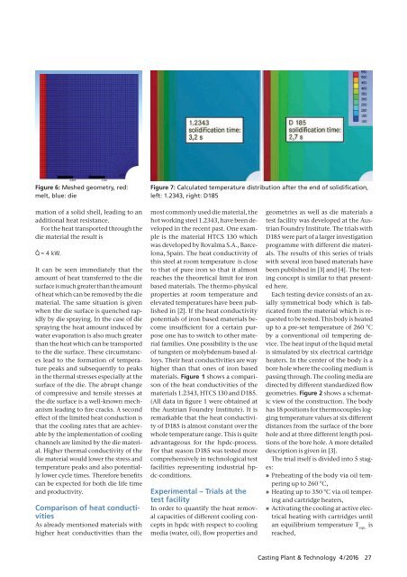
Figure 6: Meshed geometry, red:<br />
melt, blue: die<br />
Figure 7: Calculated temperature distribution after the end of solidification,<br />
left: 1.2343, right: D185<br />
mation of a solid shell, leading to an<br />
additional heat resistance.<br />
For the heat transported through the<br />
die material the result is<br />
Q˙ = 4 kW.<br />
It can be seen immediately that the<br />
amount of heat transferred to the die<br />
surface is much greater than the amount<br />
of heat which can be removed by the die<br />
material. The same situation is given<br />
when the die surface is quenched rapidly<br />
by die spraying. In the case of die<br />
spraying the heat amount induced by<br />
water eva poration is also much greater<br />
than the heat which can be transported<br />
to the die surface. These circumstances<br />
lead to the formation of temperature<br />
peaks and subsequently to peaks<br />
in the thermal stresses especially at the<br />
surface of the die. The abrupt change<br />
of compressive and tensile stresses at<br />
the die surface is a well-known mechanism<br />
leading to fire cracks. A second<br />
effect of the limited heat conduction is<br />
that the cooling rates that are achievable<br />
by the implementation of cooling<br />
channels are limited by the die material.<br />
Higher thermal conductivity of the<br />
die material would lower the stress and<br />
temperature peaks and also potentially<br />
lower cycle times. Therefore benefits<br />
can be expected for both die life time<br />
and productivity.<br />
Comparison of heat conductivities<br />
As already mentioned materials with<br />
higher heat conductivities than the<br />
most commonly used die material, the<br />
hot working steel 1.2343, have been developed<br />
in the recent past. One example<br />
is the material HTCS 130 which<br />
was developed by Rovalma S.A., Barcelona,<br />
Spain. The heat conductivity of<br />
this steel at room temperature is close<br />
to that of pure iron so that it almost<br />
reaches the theoretical limit for iron<br />
based materials. The thermo-physical<br />
properties at room temperature and<br />
elevated temperatures have been published<br />
in [2]. If the heat conductivity<br />
potentials of iron based materials become<br />
insufficient for a certain purpose<br />
one has to switch to other material<br />
families. One possibility is the use<br />
of tungsten or molybdenum-based alloys.<br />
Their heat conductivities are way<br />
higher than that ones of iron based<br />
materials. Figure 1 shows a comparison<br />
of the heat conductivities of the<br />
materials 1.2343, HTCS 130 and D185.<br />
(All data in figure 1 were obtained at<br />
the Austrian Foundry Institute). It is<br />
remarkable that the heat conductivity<br />
of D185 is almost constant over the<br />
whole temperature range. This is quite<br />
advantageous for the hpdc-process.<br />
For that reason D185 was tested more<br />
comprehensively in technological test<br />
facilities representing industrial hpdc-conditions.<br />
Experimental – Trials at the<br />
test facility<br />
In order to quantify the heat removal<br />
capacities of different cooling concepts<br />
in hpdc with respect to cooling<br />
media (water, oil), flow properties and<br />
geometries as well as die materials a<br />
test facility was developed at the Austrian<br />
Foundry Institute. The trials with<br />
D185 were part of a larger investigation<br />
programme with different die materials.<br />
The results of this series of trials<br />
with several iron based materials have<br />
been published in [3] and [4]. The testing<br />
concept is similar to that presented<br />
here.<br />
Each testing device consists of an axially<br />
symmetrical body which is fabricated<br />
from the material which is requested<br />
to be tested. This body is heated<br />
up to a pre-set temperature of 260 °C<br />
by a conventional oil tempering device.<br />
The heat input of the liquid metal<br />
is simulated by six electrical cartridge<br />
heaters. In the center of the body is a<br />
bore hole where the cooling medium is<br />
passing through. The cooling media are<br />
directed by different standardized flow<br />
geometries. Figure 2 shows a schematic<br />
view of the construction. The body<br />
has 18 positions for thermocouples logging<br />
temperature values at six different<br />
distances from the surface of the bore<br />
hole and at three different length positions<br />
of the bore hole. A more detailed<br />
description is given in [3].<br />
The trial itself is divided into 5 stages:<br />
» Preheating of the body via oil tempering<br />
up to 260 °C,<br />
» Heating up to 350 °C via oil tempering<br />
and cartridge heaters,<br />
» Activating the cooling at active electrical<br />
heating with cartridges until<br />
an equilibrium temperature T equ.<br />
is<br />
reached,<br />
Casting Plant & Technology 4 / <strong>2016</strong> 27