Eric Vittoz - IEEE
Eric Vittoz - IEEE
Eric Vittoz - IEEE

You also want an ePaper? Increase the reach of your titles
YUMPU automatically turns print PDFs into web optimized ePapers that Google loves.
TECHNICAL LITERATURE<br />
given number of gates. The computer was the IBM<br />
1130 of the University of Neuchâtel that was fed by<br />
punched cards. I was coming in the evening with my<br />
stack of cards, retrieving the result the next morning.<br />
It took me many days until my FORTRAN program<br />
was debugged, but finally I got the results, which is<br />
still valid to-day: only one 4-gate race-free divider-bytwo<br />
is possible whereas 9 solutions exist with 5 gates.<br />
The best of these 10 possibilities is the 5-gate structure<br />
illustrated in Fig. 14.<br />
Fig. 14: Race-free divide-by-two cell.<br />
The five gates and their interconnections are<br />
defined by the five equations (or rather logic implications).<br />
The input variable is I, each internal variable A<br />
to E is produced by a gate (D and E by simple inverters),<br />
and the gates are interconnected according to<br />
the set of equations. The corresponding graph of transitions<br />
shows that no more than one variable tends to<br />
transit from any given state; hence there is no race<br />
between variables. The sequence of stable states<br />
shows that each variable transits at half the input frequency<br />
and may thus be used as output of the divider<br />
stage. This circuit was integrated experimentally in a<br />
5μm silicon gate process that had been developed in<br />
the meantime 8 (Fig. 15). At 1.35V, it was consuming<br />
only 1.2nA/kHz, thus about 10 times less than the<br />
previous realization. A maximum frequency of 2MHz<br />
made it possible to use higher quartz frequencies for<br />
special products, such as the Beta 4 mentioned previously.<br />
The process itself was running on a pilot line,<br />
producing a limited quantity of industrial circuits.<br />
The asynchronous divide-by-two cell is the most<br />
elementary non-trivial sequential circuit, and computer<br />
synthesis of race-free solutions was not applicable<br />
to more complex cells. But our younger colleague<br />
Christian Piguet later developed a methodology applicable<br />
to various types of cells, including D and JK<br />
flip-flops 9 .<br />
Returning to 1972, an important contribution was<br />
brought by my senior colleague Henri Oguey. After<br />
Fig. 15: First integrated race-free frequency divider.<br />
developing display motors, Henri had been very<br />
active in the industrialization of Beta 21. Returning to<br />
circuit design, he joined our project on new CMOS<br />
frequency dividers. He soon pointed out that among<br />
all the transistors of a sequential circuit, only some are<br />
active to change the output state of each gate, by<br />
charging or discharging the output capacitor. The others<br />
are just needed to maintain established states<br />
against leakage currents. They are therefore not necessary<br />
if the frequency is high enough.<br />
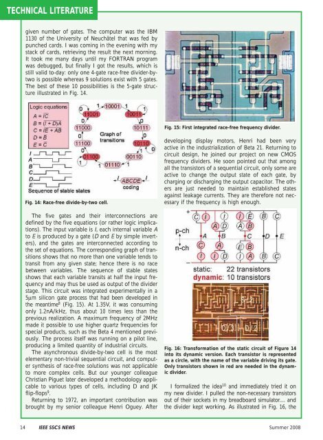
Fig. 16: Transformation of the static circuit of Figure 14<br />
into its dynamic version. Each transistor is represented<br />
as a circle, with the name of the variable driving its gate.<br />
Only transistors shown in red are needed in the dynamic<br />
divider.<br />
I formalized the idea 10 and immediately tried it on<br />
my new divider. I pulled the non-necessary transistors<br />
out of their sockets in my breadboard simulator.... and<br />
the divider kept working. As illustrated in Fig. 16, the<br />
14 <strong>IEEE</strong> SSCS NEWS Summer 2008