Eric Vittoz - IEEE
Eric Vittoz - IEEE
Eric Vittoz - IEEE

You also want an ePaper? Increase the reach of your titles
YUMPU automatically turns print PDFs into web optimized ePapers that Google loves.
TECHNICAL LITERATURE<br />
the MOS transistor is a 4-terminal device, with the<br />
gate voltage controlling what would be the specific<br />
current of the BJT.<br />
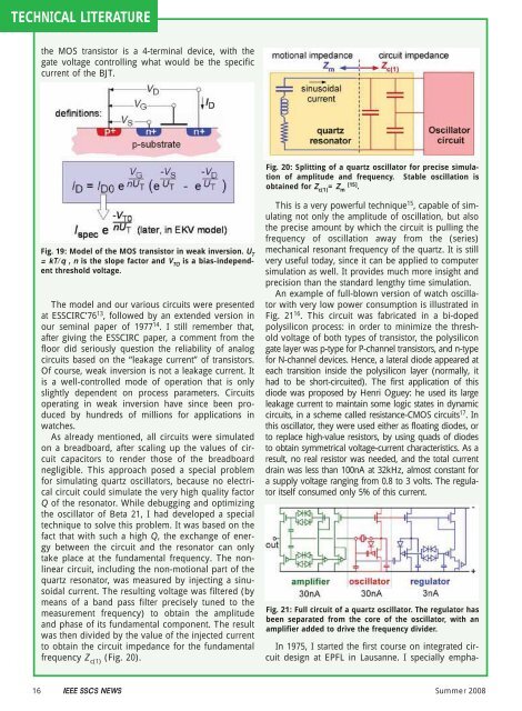
Fig. 19: Model of the MOS transistor in weak inversion. U T<br />
= kT/q , n is the slope factor and V TO is a bias-independent<br />
threshold voltage.<br />
The model and our various circuits were presented<br />
at ESSCIRC’76 13 , followed by an extended version in<br />
our seminal paper of 1977 14 . I still remember that,<br />
after giving the ESSCIRC paper, a comment from the<br />
floor did seriously question the reliability of analog<br />
circuits based on the “leakage current” of transistors.<br />
Of course, weak inversion is not a leakage current. It<br />
is a well-controlled mode of operation that is only<br />
slightly dependent on process parameters. Circuits<br />
operating in weak inversion have since been produced<br />
by hundreds of millions for applications in<br />
watches.<br />
As already mentioned, all circuits were simulated<br />
on a breadboard, after scaling up the values of circuit<br />
capacitors to render those of the breadboard<br />
negligible. This approach posed a special problem<br />
for simulating quartz oscillators, because no electrical<br />
circuit could simulate the very high quality factor<br />
Q of the resonator. While debugging and optimizing<br />
the oscillator of Beta 21, I had developed a special<br />
technique to solve this problem. It was based on the<br />
fact that with such a high Q, the exchange of energy<br />
between the circuit and the resonator can only<br />
take place at the fundamental frequency. The nonlinear<br />
circuit, including the non-motional part of the<br />
quartz resonator, was measured by injecting a sinusoidal<br />
current. The resulting voltage was filtered (by<br />
means of a band pass filter precisely tuned to the<br />
measurement frequency) to obtain the amplitude<br />
and phase of its fundamental component. The result<br />
was then divided by the value of the injected current<br />
to obtain the circuit impedance for the fundamental<br />
frequency Z c(1) (Fig. 20).<br />
Fig. 20: Splitting of a quartz oscillator for precise simulation<br />
of amplitude and frequency. Stable oscillation is<br />
obtained for Z c(1) = Z m [15] .<br />
This is a very powerful technique 15 , capable of simulating<br />
not only the amplitude of oscillation, but also<br />
the precise amount by which the circuit is pulling the<br />
frequency of oscillation away from the (series)<br />
mechanical resonant frequency of the quartz. It is still<br />
very useful today, since it can be applied to computer<br />
simulation as well. It provides much more insight and<br />
precision than the standard lengthy time simulation.<br />
An example of full-blown version of watch oscillator<br />
with very low power consumption is illustrated in<br />
Fig. 21 16 . This circuit was fabricated in a bi-doped<br />
polysilicon process: in order to minimize the threshold<br />
voltage of both types of transistor, the polysilicon<br />
gate layer was p-type for P-channel transistors, and n-type<br />
for N-channel devices. Hence, a lateral diode appeared at<br />
each transition inside the polysilicon layer (normally, it<br />
had to be short-circuited). The first application of this<br />
diode was proposed by Henri Oguey: he used its large<br />
leakage current to maintain some logic states in dynamic<br />
circuits, in a scheme called resistance-CMOS circuits 17 . In<br />
this oscillator, they were used either as floating diodes, or<br />
to replace high-value resistors, by using quads of diodes<br />
to obtain symmetrical voltage-current characteristics. As a<br />
result, no real resistor was needed, and the total current<br />
drain was less than 100nA at 32kHz, almost constant for<br />
a supply voltage ranging from 0.8 to 3 volts. The regulator<br />
itself consumed only 5% of this current.<br />
Fig. 21: Full circuit of a quartz oscillator. The regulator has<br />
been separated from the core of the oscillator, with an<br />
amplifier added to drive the frequency divider.<br />
In 1975, I started the first course on integrated circuit<br />
design at EPFL in Lausanne. I specially empha-<br />
16 <strong>IEEE</strong> SSCS NEWS Summer 2008