The Impact of Dennard's Scaling Theory - IEEE
The Impact of Dennard's Scaling Theory - IEEE
The Impact of Dennard's Scaling Theory - IEEE
- TAGS
- scaling
- www.ieee.org

You also want an ePaper? Increase the reach of your titles
YUMPU automatically turns print PDFs into web optimized ePapers that Google loves.
SSCS<br />
SSCS<br />
<strong>IEEE</strong> SOLID-STATE CIRCUITS SOCIETY NEWS<br />
Winter 2007 Vol. 12, No. 1 www.ieee.org/sscs-news<br />
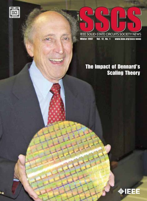
<strong>The</strong> <strong>Impact</strong> <strong>of</strong> <strong>Dennard's</strong><br />
<strong>Scaling</strong> <strong>The</strong>ory
Editor’s Column<br />
We appreciate<br />
all<br />
<strong>of</strong> your<br />
feedback on our<br />
first issue in September,<br />
2006 on “<strong>The</strong><br />
Technical <strong>Impact</strong> <strong>of</strong><br />
Moore's Law.” With the Winter, 2007<br />
issue, we are continuing our new<br />
policy <strong>of</strong> mailing a hard copy <strong>of</strong> the<br />
SSCS News to all 11,500 members.<br />
This issue is the first <strong>of</strong> four that SSCS<br />
plans to publish annually (one each<br />
in Winter, Spring, Summer, and Fall).<br />
<strong>The</strong> goal <strong>of</strong> every issue is to be a<br />
self-contained resource on a select-<br />
President:<br />
Richard C. Jaeger<br />
Alabama Microelectronics Center<br />
Auburn University, AL<br />
jaeger@eng.auburn.edu<br />
Fax: +1 334 844-1888<br />
Vice President:<br />
Willy Sansen<br />
K. U. Leuven<br />
Leuven, Belgium<br />
Secretary:<br />
David A. Johns<br />
University <strong>of</strong> Toronto<br />
Toronto, Ontario, Canada<br />
Treasurer:<br />
Rakesh Kumar<br />
Technology Connexions<br />
Poway, CA<br />
Past President:<br />
Stephen H. Lewis<br />
University <strong>of</strong> California<br />
Davis, CA<br />
Other Representatives:<br />
Representative to Sensors Council<br />
Darrin Young<br />
Representative from CAS to SSCS<br />
Domine Leenaerts<br />
Representative to CAS from SSCS<br />
Un-Ku Moon<br />
Newsletter Editor:<br />
Lewis Terman<br />
IBM T. J. Watson Research Center<br />
terman@us.ibm.com<br />
Fax: +1 914 945-4160<br />
ed topic, with background articles<br />
(that is, the ‘original sources’) and<br />
new articles by experts who<br />
describe the current state <strong>of</strong> affairs<br />
in technology and the impact <strong>of</strong> the<br />
original papers and/or patents.<br />
<strong>The</strong> theme <strong>of</strong> the Winter 2007<br />
issue is “<strong>The</strong> <strong>Impact</strong> <strong>of</strong> <strong>Dennard's</strong><br />
<strong>Scaling</strong> <strong>The</strong>ory.”<br />
This issue contains one Research<br />
Highlights article: “Analog IC Design<br />
at the University <strong>of</strong> Twente,” by<br />
Bram Nauta, Head <strong>of</strong> the IC Design<br />
Group at the University <strong>of</strong> Twente,<br />
<strong>The</strong> Netherlands. <strong>The</strong> issue also<br />
contains seven short feature articles<br />
<strong>IEEE</strong> Solid-State Circuits Society AdCom<br />
Newsletter Coeditor:<br />
Mary Y. Lanzerotti<br />
IBM T.J. Watson Research Center<br />
myl@us.ibm.com<br />
Fax: +1 914 945 1358<br />
Elected AdCom Members at Large<br />
Terms to 31 Dec. 07:<br />
Bill Bidermann<br />
David Johns<br />
Terri Fiez<br />
Takayasu Sakurai<br />
Mehmet Soyuer<br />
Terms to 31 Dec. 08:<br />
Wanda K. Gass<br />
Ali Hajimiri<br />
Paul J. Hurst<br />
Akira Matsuzawa<br />
Ian Young<br />
Terms to 31 Dec. 09:<br />
John J. Corcoran<br />
Kevin Kornegay<br />
Hae-Seung (Harry) Lee<br />
Thomas H. Lee<br />
Jan Van der Spiegel<br />
Chairs <strong>of</strong> Standing Committees:<br />
Awards David Hodges<br />
Chapters Jan Van der Spiegel<br />
Education CK Ken Yang<br />
Meetings Anantha Chandrakasan<br />
Membership Bruce Hecht<br />
Nominations Stephen H. Lewis<br />
Publications Bernhard Boser<br />
For detailed contact information, see the Society<br />
e-News: www.ieee.org/portal/site/sscs<br />
For questions regarding Society business, contact the SSCS Executive Office.<br />
Contributions for the Spring 2007 issue <strong>of</strong> the Newsletter must be received by<br />
8 February 2007 at the SSCS Executive Office. A complete media kit for advertisers<br />
is available at www.spectrum.ieee.org/mc_print. Scroll down to find SSCS<br />
Anne O’Neill, Executive Director<br />
<strong>IEEE</strong> SSCS<br />
445 Hoes Lane<br />
Piscataway, NJ 08854<br />
Tel: +1 732 981 3400<br />
Fax: +1 732 981 3401<br />
Email: sscs@ieee.org<br />
Katherine Olstein, SSCS Administrator<br />
<strong>IEEE</strong> SSCS<br />
445 Hoes Lane,<br />
Piscataway, NJ 08854<br />
Tel: +1 732 981 3410<br />
Fax: +1 732 981 3401<br />
Email: k.olstein@ieee.org<br />
that address the theme:<br />
(1) “A 30 Year Retrospective on<br />
<strong>Dennard's</strong> MOSFET <strong>Scaling</strong><br />
Paper,” by Mark Bohr <strong>of</strong> Intel<br />
Corporation;<br />
(2) “Device <strong>Scaling</strong>: <strong>The</strong> Treadmill<br />
that Fueled Three Decades <strong>of</strong><br />
Semiconductor Industry Growth,”<br />
by Pallab Chatterjee <strong>of</strong> i2 Technologies;<br />
(3) “Recollections on MOSFET<br />
<strong>Scaling</strong>,” by Dale Critchlow,<br />
the University <strong>of</strong> Vermont;<br />
(4) “<strong>The</strong> Business <strong>of</strong> <strong>Scaling</strong>,” by<br />
Rakesh Kumar, TCX, Inc. Technology<br />
Connexions;<br />
(5) “A Perspective on the <strong>The</strong>ory<br />
<strong>of</strong> MOSFET <strong>Scaling</strong> and its<br />
<strong>Impact</strong>,” by Tak Ning, IBM;<br />
(6) “<strong>Impact</strong> <strong>of</strong> <strong>Scaling</strong> and the<br />
environment in which the <strong>Scaling</strong><br />
developed<br />
at that time," by Yoshio Nishi, Stanford<br />
University;<br />
(7) "It's All About Scale," by Hans<br />
Stork, TI.<br />
Three original papers by Dennard,<br />
from 1972 (IEDM Conference),<br />
1973 (IEDM Conference), and 1974<br />
(<strong>IEEE</strong> Journal <strong>of</strong> Solid-State Circuits),<br />
are also reprinted in this<br />
issue.<br />
Thank you for taking the time to<br />
read the SSCS News. We appreciate<br />
your comments and feedback! Please<br />
send comments to myl@us.ibm.com.<br />
2 <strong>IEEE</strong> SSCS NEWSLETTER Winter 2007
Winter 2007 Volume 12, Number 1<br />
Editor’s Column . . . . . . . . . . . . . . . . . . . . . . . . . . . . . . . . . . . . . . . . . . . .2<br />
President’s Message . . . . . . . . . . . . . . . . . . . . . . . . . . . . . . . . . . . . . . . .4<br />
Corrections . . . . . . . . . . . . . . . . . . . . . . . . . . . . . . . . . . . . . . . . . . . . . . .4<br />
20<br />
51<br />
56<br />
©Copyright IBM<br />
Corporation 2006.<br />
All rights reserved.<br />
Reproduced by<br />
permission <strong>of</strong> IBM<br />
Corporation.<br />
RESEARCH HIGHLIGHTS<br />
Analog IC Design at the University <strong>of</strong> Twente . . . . . . . . . . . . . . . . . .5<br />
TECHNICAL LITERATURE<br />
A 30 Year Retrospective on Dennard’s MOSFET <strong>Scaling</strong> Paper . . .11<br />
Device <strong>Scaling</strong>: <strong>The</strong> Treadmill that Fueled Three Decades <strong>of</strong> Semiconductor<br />
Industry Growth . . . . . . . . . . . . . . . . . . . . . . . . . . . . . . . .14<br />
Recollections on MOSFET <strong>Scaling</strong> . . . . . . . . . . . . . . . . . . . . . . . . . . .19<br />
<strong>The</strong> Business <strong>of</strong> <strong>Scaling</strong> . . . . . . . . . . . . . . . . . . . . . . . . . . . . . . . . . . .22<br />
A Perspective on the <strong>The</strong>ory <strong>of</strong> MOSFET <strong>Scaling</strong> and its <strong>Impact</strong> . .27<br />
<strong>The</strong> <strong>Impact</strong> <strong>of</strong> <strong>Scaling</strong> and the <strong>Scaling</strong> Development Environment 31<br />
It’s All About Scale . . . . . . . . . . . . . . . . . . . . . . . . . . . . . . . . . . . . . .33<br />
Design <strong>of</strong> Micron MOS Switching Devices . . . . . . . . . . . . . . . . . . . .35<br />
Ion Implanted MOSFET’s with Very Short Channel Lengths . . . . . . .36<br />
Design <strong>of</strong> Ion-Implanted MOSFET’s with Very Small Physical Dimensions 38<br />
PEOPLE<br />
An Interview with James Meindl - 2006 <strong>IEEE</strong> Medal <strong>of</strong> Honor Recipient 51<br />
Hugo De Man Awarded for Leadership in Integrated Circuit Design . .53<br />
Yannis P. Tsividis to Receive <strong>IEEE</strong> Kirchh<strong>of</strong>f Award . . . . . . . . . . . . . . . . . . .56<br />
<strong>IEEE</strong> Educational Innovation Award to Terri Fiez . . . . . . . . . . . . . . . . . . . . .58<br />
16 New Speakers Diversify SSCS Distinguished Lecturer Program . . . . . .61<br />
New Senior Members . . . . . . . . . . . . . . . . . . . . . . . . . . . . . . . . . . . . . . . . . .67<br />
Tools: How to Write Readable Reports and Winning Proposals . . . . . . . .67<br />
CHAPTER NEWS<br />
SSCS Awards $35,000 in Chapter Subsidies . . . . . . . . . . . . . . . . . . . . . . . .69<br />
Far East Chapters Meet in Hangzhou, China . . . . . . . . . . . . . . . . . . . . . .70<br />
V. Oklobdzija Offers <strong>IEEE</strong> DL Talks in Western Australia . . . . . . . . . . . .71<br />
Denver Hosts Technical Seminars on Cutting-Edge CMOS Technology .72<br />
CONFERENCES<br />
Second A-SSCC Considers Challenges for the e-Life . . . . . . . . . . .74<br />
Solid-State Circuits Conference Will Focus on Nano-Era Synergy . .76<br />
Invitation from the ISSCC 2007 Chair . . . . . . . . . . . . . . . . . . . . . . . .75<br />
AACD Conference Will Convene on 27-29 March 2006 . . . . . . . . .78<br />
NEWS<br />
SSCS AdCom Election for 2007-2009 Term . . . . . . . . . . . . . . . . . . . . . . .80<br />
<strong>IEEE</strong> Design Council Newsletter Completes Inaugural Year . . . . . . . . . .80<br />
<strong>IEEE</strong> Teaching Awards . . . . . . . . . . . . . . . . . . . . . . . . . . . . . . . . . . . . . . . . .81<br />
Call for Nominations: SSCS Predoctoral Fellowships . . . . . . . . . . . . . . . .82<br />
Winter 2007 <strong>IEEE</strong> SSCS NEWSLETTER 3
Message from the President<br />
In 2007, look for an unadvertised bonus<br />
with your SSCS membership: A free<br />
subscription to the brand new quarterly<br />
Nanotechnology Magazine. We believe<br />
that circuit experts need to be in touch<br />
with this rapidly progressing technology.<br />
Some day it will be a fruitful area<br />
for circuits development, and opportunities to contribute<br />
will arise.<br />
<strong>The</strong> minimal subscription cost to the Society for the<br />
launch year <strong>of</strong> the new magazine prompted the AdCom<br />
to join the Nanotechnology Council. We hope the<br />
Council’s magazine effort will be <strong>of</strong> comparable interest<br />
to its Transactions on Nanotechnology, which is just<br />
beginning its sixth year and has among the highest rates<br />
<strong>of</strong> citation as measured by the Thompson ISI. I would<br />
like to receive feedback from you on how useful a tool<br />
the new magazine is. Look for the first issue in the<br />
spring <strong>of</strong> 2007.<br />
2007 is the Society’s 10th anniversary, having<br />
evolved from the Solid-State Circuits Council that originated<br />
in 1970. We’ve updated the SSCS logo for this<br />
year to draw attention to our progress. Since 1997, the<br />
Journal <strong>of</strong> Solid-State Circuits has increased coverage <strong>of</strong><br />
technical articles by 40%, and the SSCS Newsletter by 2<br />
1/2 times. <strong>The</strong> JSSC continues to be the most read in<br />
<strong>IEEE</strong> Xplore and the most cited in patents. Your SSCS<br />
membership provides online access not only to the<br />
Journal but also to the digests <strong>of</strong> our five major solidstate<br />
circuits conferences and most <strong>of</strong> their historic<br />
record. Local chapters have grown from 2 to 59, with<br />
Corrections<br />
In the article entitled “Overview <strong>of</strong><br />
CMOS Technology Development in<br />
the MIRAI Project,” by Toshiaki<br />
Masuhara and Masataka Hirose in<br />
the September 2006 issue, the last<br />
sentence in the Section entitled<br />
“New Circuits and System Technology<br />
- Post-fabrication Adaptive<br />
Adjustment” contains an incorrect<br />
expression, which is corrected as in<br />
the underlined expression in the following<br />
sentence:<br />
“As shown in Fig. 3, the developed<br />
tool successfully extracted the<br />
34 model parameters in 23 hours<br />
with a PC and resulted in a mean<br />
RMS error <strong>of</strong> 1.83% for benchmark<br />
MOSFETs.”<br />
In the Section, “New Gate Stack<br />
Technology with High-k Materials”,<br />
the caption for Figure 4 should read:<br />
Fig. 4 Gate leakage current in<br />
MIRAI HfAlON formed by Layer-by-<br />
Layer Deposition and Annealing<br />
(LL-D&A) 4 ).<br />
(a) Comparison <strong>of</strong> gate leakage current<br />
in MOSFETs with HfAlON<br />
gate insulator and HfSiON 5 ).<br />
(b) Cross sectional TEM micrograph<br />
<strong>of</strong> HfAlON/SiO 2 /Si gate stack<br />
formed by Layer-by-Layer Deposition<br />
and Annealing.<br />
<strong>The</strong> following corrections pertain<br />
to the reprint <strong>of</strong> “Lithography and<br />
the Future <strong>of</strong> Moore’s Law” (Moore,<br />
1995) in the September 2006 issue:<br />
I have reproduced photomicrographs<br />
<strong>of</strong> the first planar transistor<br />
the recent addition <strong>of</strong> Tainan (Taiwan) and South<br />
Brazil. Celebrate our anniversary by browsing your<br />
technical articles online.<br />
I’ve been active in the last quarter attending many <strong>of</strong><br />
the conferences that SSCS cosponsors to sample their<br />
quality, focus, and differences, as well as to increase the<br />
Society’s visibility and support for these important gatherings<br />
<strong>of</strong> technical experts. ESSCIRC in Montreux,<br />
Switzerland last fall was fully overlapped with the ESS-<br />
DERC device conference. One was able to move freely<br />
between the co-located meetings. <strong>The</strong> wide variety <strong>of</strong><br />
plenary topics covered by the two meetings was <strong>of</strong> particular<br />
interest. Welcoming the Asian-Solid-State Circuits<br />
Conference in Hangzhou, China two months later, I was<br />
able to talk with circuit experts from around the world,<br />
and by the time this issue reaches you, I will have celebrated<br />
the opening <strong>of</strong> the 20th International Conference<br />
on VLSI Design in Bangalore.<br />
Thanks to all <strong>of</strong> our members who voted in our fall<br />
election. Welcome to our new additions to AdCom,<br />
Kevin Kornegay from Georgia Tech and Harry Lee from<br />
MIT. And welcome back to returning AdCom members<br />
John Corcoran from Agilent Laboratories, Tom Lee from<br />
Stanford, and Jan Van der Spiegel from the University <strong>of</strong><br />
Pennsylvania. <strong>The</strong> Society is beginning a review <strong>of</strong> its<br />
priorities for 2007 and beyond. As Society members,<br />
please make your interests known to your AdCom representatives.<br />
Start a conversation and help the Society<br />
point to the future that you feel is coming.<br />
Richard C. Jaeger<br />
and the first commercially-available<br />
integrated circuit in Figs 3 & 4. I am<br />
particularly fond <strong>of</strong> the transistor,<br />
since it is one <strong>of</strong> the very few products<br />
that I designed myself that<br />
actually went into production.<br />
Fig. 3. Photomicrograph <strong>of</strong> the first<br />
commercial planar transistor.<br />
continued on page 10<br />
4 <strong>IEEE</strong> SSCS NEWSLETTER Winter 2007
Analog IC Design at the University <strong>of</strong> Twente<br />
Bram Nauta, IC Design Group, University <strong>of</strong> Twente, Enschede, <strong>The</strong> Netherlands,<br />
b.nauta@utwente.nl<br />
Introduction<br />
This article describes some recent research results<br />
from the IC Design group <strong>of</strong> the University <strong>of</strong> Twente,<br />
located in Enschede, <strong>The</strong> Netherlands.<br />
Our research focuses on analog CMOS circuit<br />
design with emphasis on high frequency and broadband<br />
circuits. With the trend <strong>of</strong> system integration in<br />
mind, we try to develop new circuit techniques that<br />
enable the next steps in system integration in<br />
nanometer CMOS technology. Our research funding<br />
comes from industry, as well as from governmental<br />
organizations. We aim to find fundamental solutions<br />
for practical problems <strong>of</strong> integrated circuits realized in<br />
industrial Silicon technologies.<br />
CMOS IC technology is dictated by optimal cost and<br />
performance <strong>of</strong> digital circuits and is certainly not<br />
optimized for nice analog behavior. As analog designers,<br />
we do not have the illusion <strong>of</strong> being able to<br />
change CMOS technology, so we have to “live with it”<br />
and solve the problems by design. In this article several<br />
examples will be shown where problematic analog<br />
behavior, such as noise and distortion, can be tackled<br />
with new circuit design techniques. <strong>The</strong>se circuit<br />
techniques are developed in such a way that they do<br />
benefit from modern technology and thus enable further<br />
integration. This way we can improve various<br />
analog building blocks for wireless, wire-line and optical<br />
communication. Below some examples are given.<br />
<strong>The</strong>rmal Noise Cancelling<br />
Noise is an important issue; in communication circuits<br />
the sensitivity <strong>of</strong> the receiver is limited by the noise<br />
level <strong>of</strong> the circuits. Especially, the noise <strong>of</strong> the first<br />
amplifier in the receiving chain is <strong>of</strong> high importance,<br />
since after that amplifier the signal is stronger and the<br />
allowable noise levels are higher. For narrowband<br />
receivers the added noise <strong>of</strong> the amplifier can be<br />
reduced relatively easily. This is done by using resonant<br />
structures, built with - for example - integrated<br />
spiral inductors and capacitors which provide voltage<br />
gain <strong>of</strong> the narrowband signals and therefore needing<br />
less gain from “noisy” transistors. For wideband systems,<br />
e.g. for TV tuners, UWB (Ultra Wide Band)<br />
communication and future s<strong>of</strong>tware defined radio,<br />
several octaves <strong>of</strong> bandwidth are needed and simple<br />
resonant structures cannot be used. For these applications,<br />
low noise gain stages using noisy transistors<br />
have to be used, which is quite a challenge. Apart<br />
from the gain and noise demands, additional<br />
demands, such as input impedance matching and<br />
good linearity, need to be satisfied.<br />
RESEARCH HIGHLIGHTS<br />
Figure 1a shows a wide band first amplifier stage,<br />
denoted as a common-source feedback amplifier.<br />
Fig 1a: common source LNA with impedance matching,<br />
the signals at nodes X and Y have opposite sign.<br />
Fig 1b: <strong>The</strong> noise <strong>of</strong> M1 generates in-phase noise voltages<br />
at nodes X and Y.<br />
<strong>The</strong> input impedance is 1/g m <strong>of</strong> M1, and must be<br />
equal to the source impedance Rs, usually 50 Ohms.<br />
With this in mind the gm <strong>of</strong> M1 is fixed by design<br />
resulting in poor noise behavior <strong>of</strong> the amplifier: <strong>The</strong><br />
"noise figure" is always larger than 3dB. In order to<br />
reduce the noise one would like to increase the g m <strong>of</strong><br />
M1 (preferably g m>>1/Rs for minimal noise figure) but<br />
then the input impedance does not match anymore.<br />
Conventionally, additional feedback techniques are<br />
used to break this paradox, but at the cost <strong>of</strong> stability<br />
and bandwidth issues.<br />
PhD Student Federico Bruccoleri realized, however,<br />
that generated noise can be cancelled by proper<br />
circuit design. If we take a look at Figure 1b, we can<br />
see how the noise current <strong>of</strong> M1 flows in the circuit;<br />
this is indicated by the red arrow.<br />
<strong>The</strong> noise current due to M1 flows in a loop,<br />
through Rs. This noise current generates a noise voltage<br />
at nodes X and Y which are <strong>of</strong> different magnitude<br />
but <strong>of</strong> the same phase. <strong>The</strong> signals nodes X and<br />
Y are in anti-phase due to the inverting nature <strong>of</strong> this<br />
amplifier. So somehow it should be possible to separate<br />
the signal from the noise!<br />
By adding an additional amplifier “A,” as shown in<br />
Figure 2, we can construct an output signal in such a<br />
way the wanted signals at nodes X and Y are added<br />
and that the noise at nodes X and Y are cancelled [1].<br />
This way we can cancel the noise <strong>of</strong> M1, which holds<br />
for both thermal and 1/f noise. Of course amplifier<br />
“A” will now add additional noise, but this needs not<br />
to be a problem. <strong>The</strong> reason for this is that in contrast<br />
to M1, we can choose the gm <strong>of</strong> the input stage <strong>of</strong><br />
amplifier “A” relatively large, and thus make it low-<br />
Winter 2007 <strong>IEEE</strong> SSCS NEWSLETTER 5
RESEARCH HIGHLIGHTS<br />
Fig 2: Basic idea <strong>of</strong> noise cancelling; the noise due to M1<br />
is cancelled.<br />
noise. So we don't break the laws <strong>of</strong> physics: we still<br />
have to burn power (in amplifier “A”) to get a lownoise<br />
amplifier, but we have created a degree <strong>of</strong> freedom<br />
by decoupling the input matching (g m1 =1/Rs)<br />
and allowing a large gm ( g mA>>1/Rs) in the amplifier<br />
A. <strong>The</strong> noise <strong>of</strong> I bias is cancelled as well. A prototype<br />
amplifier has been realized on silicon and it worked<br />
well: the noise figure was well below 3dB, which<br />
proves the concept <strong>of</strong> noise canceling. Also the<br />
robustness to mismatch in the two noise paths is good<br />
[1]. Other topologies are also possible <strong>of</strong>fering “balun”<br />
functionality [1,2].<br />
Low Frequency noise reduction in MOSFETS<br />
Low frequency (LF) transistor noise, also denoted as<br />
1/f noise, is <strong>of</strong> great importance in today's circuit<br />
design. Especially, baseband circuits suffer from this<br />
noise phenomenon which can be dominant well<br />
above 10MHz. Also high-frequency oscillators suffer<br />
from LF noise, since this noise is up-converted and<br />
appears close to the carrier frequency <strong>of</strong> the oscillator<br />
degrading the close-in phase noise.<br />
A while ago, a MSc student Gian Hoogzaad did<br />
calculations on the phase noise <strong>of</strong> CMOS inverterbased<br />
ring oscillators. <strong>The</strong>se oscillators were free<br />
running, and we expected a large close-in phase<br />
noise due to the low frequency noise <strong>of</strong> the MOS-<br />
FETs in the oscillator. Measurements, however,<br />
showed a much lower, (8dB less), close-in phase<br />
noise than we expected from the LF noise <strong>of</strong> those<br />
single transistors. <strong>The</strong> student and his supervisor<br />
Sander Gierkink were very confident <strong>of</strong> his calculations,<br />
and we were thus wondering what caused the<br />
8dB lower close-in phase noise.<br />
Finally, we suspected that the large signal switching<br />
behavior in the inverters caused the strange effect<br />
and we carried out measurements on stand-alone<br />
transistors under normal bias and under “switched<br />
bias”. Figure 3 illustrates these conditions.<br />
One would expect 6 dB less noise from the<br />
switched bias transistors compared to the normal one:<br />
3dB reduction due to the 50% duty-cycle <strong>of</strong> the noise<br />
and another 3dB due to up-conversion <strong>of</strong> the LF noise.<br />
Fig. 3: MOSFET under constant bias (blue) and switched<br />
bias (red)<br />
Measurements however showed 6 + 8 = 14 dB reduction<br />
for frequencies lower than the switching frequency,<br />
as illustrated with the red curve in Figure 4.<br />
This matched to the 8dB reduction <strong>of</strong> phase noise<br />
in the inverter ring-oscillator. This reduction takes<br />
place for frequencies lower than the switching frequency.<br />
Later, we discovered that a similar noise phenomenon<br />
had been observed before in physicists'<br />
device experiments[3]; however, we could not find a<br />
citation to this paper.<br />
Fig. 4: Measured LF noise <strong>of</strong> a MOSFET under constant<br />
bias (blue), expected 6 dB reduction under switched bias<br />
(red dashed curve) and measured behavior with intrinsic<br />
reduced noise (red)<br />
So, in fact, all inverter based ring oscillators benefited<br />
already from this phenomenon while none <strong>of</strong><br />
the designers apparently realized this. To a large<br />
extent this is because the “switched bias” noise reduction<br />
is not modeled in today's simulators. Also, the<br />
effect can be masked by the very large spread which<br />
is normally present in LF noise, especially for small<br />
area devices.<br />
After a study carried out in the PhD projects by<br />
Arnoud van der Wel and Jay Kolhatkar, the phenomena<br />
could be explained by the bias dependency <strong>of</strong><br />
the emission and capture time constants which are<br />
responsible for the trapping and de-trapping <strong>of</strong> oxidecharge<br />
in MOSFETs. This trapping and de-trapping<br />
6 <strong>IEEE</strong> SSCS NEWSLETTER Winter 2007
causes so-called random telegraph signals, which<br />
determine the low frequency noise <strong>of</strong> the transistors.<br />
<strong>The</strong> reduction effect is found to be present in all technologies<br />
investigated: from 10μm down to 0.12μm,<br />
both N and P MOSFETs and works for switching frequencies<br />
up to at least 3GHz.<br />
For large-geometry transistors we generally see a<br />
significant reduction, whereas for very small-sized<br />
modern devices the noise can decrease but also<br />
increase. This is due to the very small number <strong>of</strong><br />
traps in the transistors (sometimes only one trap)<br />
while the phenomenon depends strongly on the<br />
energy distribution <strong>of</strong> the traps. Details can be<br />
found in [4].<br />
Other known techniques to reduce the effect <strong>of</strong> LF<br />
noise in electronic circuits are chopping and correlated<br />
double sampling. <strong>The</strong> LF noise can also be<br />
reduced by increasing gate area <strong>of</strong> the MOSFETS, at<br />
the cost <strong>of</strong> area and/or power consumption. <strong>The</strong><br />
switched bias technique <strong>of</strong>fers an orthogonal method<br />
to reduce the intrinsic LF noise in the transistor itself.<br />
It is beneficial especially in circuits where switching<br />
already occurs, such as oscillators and discrete time<br />
circuits.<br />
Distortion Cancelling using Poly-Phase<br />
Technique<br />
In deep submicron technology, distortion becomes<br />
an increasing problem. Large signals are required<br />
for dynamic range reasons or simply because for a<br />
given radio standard dictates the output power to be<br />
delivered by a power amplifier. <strong>The</strong> transistors,<br />
however, have less voltage gain and exhibit very<br />
non-linear behavior, which makes linear circuit<br />
design a challenge.<br />
We know that in differential circuit the even harmonics<br />
are cancelled if the signals are in anti-phase.<br />
With this in mind, MSc student Eisse Mensink investigated<br />
whether it would be possible to use more than<br />
2 paths and multiple phases <strong>of</strong> the signal (poly-phase)<br />
and cancel more than 2 harmonics. <strong>The</strong> basic idea is<br />
shown in Figure 5, where the signal path is split in N<br />
separate parallel paths.<br />
N=2 equals the well-known differential circuit<br />
topology to cancel even harmonics. If phase shifters<br />
are available before and after the nonlinear circuit, the<br />
structure <strong>of</strong> Fig. 5 can cancel the harmonics up to N-<br />
1 [5]. <strong>The</strong> problem is however that wide-band phase<br />
shifters are very hard to implement with analog circuits.<br />
For this reason, we choose to use mixers as second<br />
phase shifters, as shown in Figure 6.<br />
<strong>The</strong> mixers each have a Local Oscillator (LO) input<br />
with each a different phase, equally divided over<br />
360/N degrees. Since we automatically get up-conversion<br />
<strong>of</strong> our input signal with these mixers, we strategically<br />
changed our plan and decided to build an RF<br />
RESEARCH HIGHLIGHTS<br />
Fig. 5: N path poly-phase circuit can cancel up to the N-1 th<br />
harmonic.<br />
power up-converter. In this up-converter the first<br />
phase shifters are assumed to be implemented in the<br />
digital baseband, while in the up-conversion mixers<br />
all problematic harmonics due to nonlinearities <strong>of</strong> the<br />
N power amplifier stages can be cancelled via the<br />
poly-phase technique in combination with a 1/3 dutycycle<br />
LO-signal [6].<br />
A silicon realization, designed by MSc Student<br />
Fig 6: Wide band phase shifters can be implemented with<br />
mixers, resulting in up-converter behavior.<br />
Rameswor Shrestha, is based on the circuit <strong>of</strong> Fig. 7<br />
with N=18 [6]. <strong>The</strong> colors in Figure 7 correspond to<br />
the colors <strong>of</strong> the functional blocks <strong>of</strong> Figure 6.<br />
Rameswor demonstrated a power up-conversion<br />
mixer, which is driven in compression while all harmonics<br />
and their sidebands, up to the 17 th harmonic,<br />
still remain under -40dBc. Without this poly-phase<br />
topology (i.e. for N=1) the harmonics would be below<br />
only -6dBc, which clearly demonstrates the effectiveness<br />
<strong>of</strong> the technique - 34 dB improvement. <strong>The</strong> RF<br />
frequency could be varied from DC to 2.5GHz and the<br />
final accuracy <strong>of</strong> the technique was limited by timing<br />
<strong>of</strong> the LO phases.<br />
Conventional RF up-converters require expensive<br />
post-filters, dedicated for every RF frequency to filter<br />
out the harmonics and sidebands in order to satisfy<br />
the radio transmit mask. With this poly-phase up-converter<br />
the harmonics can be rejected and the filter<br />
demands can be much relaxed. Applications <strong>of</strong> this<br />
poly-phase up-converter can probably be found in<br />
wide band flexible up-converters and s<strong>of</strong>tware radio<br />
transmitters, where the actual RF frequency is a priori<br />
Winter 2007 <strong>IEEE</strong> SSCS NEWSLETTER 7
RESEARCH HIGHLIGHTS<br />
not known and is free to be chosen in a given<br />
range.<br />
Pulse Width Modulation Cable Equalizer<br />
For digital data communication over copper cables,<br />
electronic equalizer circuits are used to compensate<br />
for the losses and reflections over the cables. Thanks<br />
to these electronic circuits, higher data rates can be<br />
achieved over relatively cheap cables. Examples are<br />
USB and LAN.<br />
A well known technique used at the transmitter<br />
side is pre/de-emphasis, effectively high-pass filtering<br />
the transmitted signal. This way the low-pass characteristic<br />
<strong>of</strong> the cable is compensated for. <strong>The</strong>se transmit<br />
pre-emphasis filters are generally implemented<br />
with Finite Impulse Response (FIR) filters, most <strong>of</strong>ten<br />
with just a few symbol spaced taps.<br />
As an alternative to FIR filters Daniel Schinkel and<br />
Jan-Rutger Schrader proposed Pulse Width Modulation<br />
(PWM) on a digitally coded signal [7,8]: If a ‘1’-bit<br />
has to be transmitted, a 1-0 pattern is transmitted in<br />
one bit time and if a ‘0’-bit has to be transmitted a 0-<br />
1 pattern is transmitted in one bit time. This is similar<br />
to Manchester coding but with adjustable, non-50%<br />
duty-cycle. <strong>The</strong> duty-cycle <strong>of</strong> the 1-0 and 0-1 pattern<br />
is chosen in such a way that it compensates for the<br />
cable loss. This is illustrated in Figure 8, where the<br />
duty-cycle <strong>of</strong> a 1-0 pattern is varied and the corresponding<br />
cable responses are plotted.<br />
Thus, by changing the duty-cycle, the transmitted<br />
spectrum, in which the lower frequencies are attenuated,<br />
is tuned for the high-frequency loss <strong>of</strong> the cable.<br />
In a real application an adaptive loop with returnchannel<br />
communication takes care for this tuning,<br />
similar as in a conventional FIR approach. A test chip<br />
achieved 5Gb/s over 25m <strong>of</strong> RG-58U coaxial cable<br />
which has a loss <strong>of</strong> 33 dB at the Nyquist frequency <strong>of</strong><br />
2.5GHz [8] . <strong>The</strong> eye diagram for various duty-cycles<br />
is shown in Figure 9: for this 10m long cable 66% is<br />
the optimum duty-cycle.<br />
<strong>The</strong> PWM technique can compensate for higher<br />
loss compensation (33 dB in contrast to approximately<br />
20dB for 2 tap symbol-spaced FIR) because the<br />
resulting spectrum has a better match to the skin-<br />
Fig 7: Basic circuit <strong>of</strong> Power up-converter. Fig. 8: Transmitting a “1” using PWM pre-emphasis: tuning<br />
the duty-cycle <strong>of</strong> the 1-0 pattern can compensate for<br />
the cable response.<br />
effect and dielectric loss <strong>of</strong> the cable. Still only one<br />
tuning “knob” is required to fit the transfer function to<br />
the cable. Moreover the technique is insensitive to<br />
slew-rate distortion and requires only two discrete<br />
amplitudes at the TX output (with a continuously<br />
adjustable duty-cycle), which makes it suitable for<br />
modern CMOS technologies. <strong>The</strong> technique was also<br />
successfully applied earlier for very long on-chip RC<br />
limited interconnects by Daniel Schinkel and Eisse<br />
Mensink [7].<br />
Fig 9: 5Gb/s eye patterns <strong>of</strong> transmitted signals (TX) and<br />
received signals (RX) for duty-cycle settings <strong>of</strong> 100% (normal<br />
data) , 66% (optimal PWM) and 50% (overcompensated<br />
PWM) over 10m RG-58CU cable.<br />
Optical Detectors in Standard CMOS<br />
Traditionally, in optical communication extremely<br />
high data rates have to be achieved over long distances.<br />
<strong>The</strong>refore optical communication is the<br />
domain <strong>of</strong> expensive exotic technologies and the high<br />
8 <strong>IEEE</strong> SSCS NEWSLETTER Winter 2007
costs associated with it can be shared between many<br />
users. For optical communication over short distances<br />
(meters) or very short distances (optical interconnect),<br />
cost issues, however, do play a crucial role. <strong>The</strong>refore,<br />
we started a project to integrate an optical detector<br />
in standard CMOS technology; the optical data signal<br />
can now shine directly on a digital CMOS chip.<br />
Due to the availability <strong>of</strong> low-cost high-speed laser at<br />
850nm wavelength and the compatibility with both<br />
inexpensive plastic fibers and with photo-generation<br />
in silicon, our work mainly uses this 850nm.<br />
An essential part <strong>of</strong> an optical detector in CMOS is<br />
the integrated photodiode structure, shown in the leftmost<br />
inset in Figure 10.<br />
Fig. 10: Transmitting a “1” using PWM pre-emphasis: tuning<br />
the duty-cycle <strong>of</strong> the 1-0 pattern can compensate for<br />
the cable response.<br />
Incident photons are absorbed in the silicon at tens<br />
<strong>of</strong> microns deep, much deeper than any junction in<br />
standard CMOS. In the absorption process, electrons<br />
and holes are generated and most <strong>of</strong> them slowly diffuse<br />
to the pn-junctions where the actual detection<br />
takes place. <strong>The</strong> slow diffusion causes the -3dB bandwidth<br />
<strong>of</strong> the photodiode to be in the order <strong>of</strong> 5 MHz,<br />
which causes a serious speed problem. In literature<br />
authors generally modify the technology, e.g. to allow<br />
high voltages and very wide depletion layers to boost<br />
the speed <strong>of</strong> the carriers, however this implies that<br />
non-standard CMOS has to be used. <strong>The</strong> maximal<br />
speed reported in standard CMOS so far has been<br />
700Mbit/sec.<br />
Ph.D. student Sasa Radovanovic implemented<br />
another solution. Although the -3dB frequency is<br />
very low, the roll-<strong>of</strong>f per decade <strong>of</strong> frequency<br />
appears to be very low as well; only 3 to 4 dB per<br />
decade, up to in the low GHz region. <strong>The</strong>refore, Sasa<br />
used an analog equalizer, with opposite frequency<br />
characteristic after the transimpedance amplifier following<br />
the diode to get a flat overall response up to<br />
a few GHz. One might assume that the production<br />
spread in time constants between the equalizer and<br />
the diode itself might ruin the performance, but<br />
RESEARCH HIGHLIGHTS<br />
thanks to the low roll <strong>of</strong>f, even +/- 20% spread in<br />
time constants hardly affects the time pulses. <strong>The</strong><br />
resulting chip achieved 3Gbit/sec in standard 0.18μm<br />
CMOS, with a BER <strong>of</strong> 10 -11 at an optical input power<br />
<strong>of</strong> 25μW [9]. <strong>The</strong> speed limitation was in the electronic<br />
circuit, and is expected to scale with technology.<br />
This result enables high speed optical inputs for<br />
standard CMOS chips.<br />
Conclusion<br />
Several examples <strong>of</strong> new design methodologies have<br />
been illustrated. <strong>The</strong>se methodologies benefit from<br />
modern CMOS technology and may be helpful for<br />
future system integration. More work can be found at<br />
the URL: http://icd.ewi.utwente.nl<br />
Acknowledgements<br />
<strong>The</strong> work described in this article has been carried<br />
out by many students; however, without the supervision<br />
or help from Eric Klumperink, Anne Johan<br />
Annema, Ed van Tuijl, Ronan van der Zee, Gerard<br />
Wienk and Henk de Vries, these results would not<br />
have been here. This work has been funded by: STW,<br />
FOM and MESA +. Philips and CERN are acknowledged<br />
for providing silicon access.<br />
References<br />
[1] F. Bruccoleri, E.A.M. Klumperink, B. Nauta,<br />
“Wide-Band CMOS Low-Noise Amplifier Exploiting<br />
<strong>The</strong>rmal-Noise Canceling”, <strong>IEEE</strong> Journal <strong>of</strong><br />
Solid-State Circuits, Vol. 39, No. 2, pp. 275 -282,<br />
February 2004.<br />
[2] S. Chehrazi, A. Mirzaei, R. Bagheri, A. A. Abidi;<br />
“A 6.5 GHz wideband CMOS low noise amplifier<br />
for multi-band use”, 2005 <strong>IEEE</strong> Custom Integrated<br />
Circuits Conference18, pp. 801 - 804, September<br />
2005.<br />
[3] I. Bloom and Y. Nemirovsky, “1/f noise reduction<br />
<strong>of</strong> metal-oxide semiconductor transistors by<br />
cycling from inversion to accumulation”, Applied<br />
Physics Letters, vol. 58, no. 15, pp. 1664–1666,<br />
Apr. 1991.<br />
[4] A.P. van der Wel , E.A.M. Klumperink , J. Kolhatkar<br />
, E. Hoekstra, M. Snoeij , C. Salm, H.<br />
Wallinga and B. Nauta “Low Frequency Noise<br />
Phenomena in Switched MOSFETs”, <strong>IEEE</strong> Journal<br />
<strong>of</strong> Solid State Circuits, Vol. 42, No.3, March 2007.<br />
[5] E. Mensink, E.A.M. Klumperink, B.Nauta, “Distortion<br />
Cancellation by Polyphase Multipath Circuits,”<br />
<strong>IEEE</strong> TCAS-I, pp. 1785-1794, Sept. 2005.<br />
[6] R. Shrestha, E.A.M. Klumperink, E. Mensink, G.<br />
Wienk, B. Nauta, “A Polyphase Multipath Technique<br />
for S<strong>of</strong>tware Defined Radio Transmitters”,<br />
<strong>IEEE</strong> Journal <strong>of</strong> Solid State Circuits, Vol. 41,<br />
No.12, Dec 2006.<br />
[7] D. Schinkel., E. Mensink, E.A.M. Klumperink,<br />
A.J.M. van Tuijl, B. Nauta, “A 3Gb/s/ch Transceiver<br />
Winter 2007 <strong>IEEE</strong> SSCS NEWSLETTER 9
RESEARCH HIGHLIGHTS<br />
for 10-mm Uninterrupted RC-Limited Global On-<br />
Chip Interconnects”, <strong>IEEE</strong> Journal <strong>of</strong> Solid State<br />
Circuits, Vol. 41, No. 1, pp. 297- 306, Jan. 2006.<br />
[8] J.H.R. Schrader, E.A.M. Klumperink, J.L. Visschers,<br />
B. Nauta, “Pulse-Width Modulation Pre<br />
Emphasis applied in a Wireline Transmitter,<br />
achieving 33dB Loss Compensation at 5-Gb/s in<br />
About the Author<br />
Bram Nauta was born in Hengelo,<br />
<strong>The</strong> Netherlands. In 1987 he<br />
received the M.Sc degree (cum<br />
laude) in electrical engineering from<br />
the University <strong>of</strong> Twente, Enschede,<br />
<strong>The</strong> Netherlands. In 1991 he<br />
received the Ph.D. degree from the<br />
same university on the subject <strong>of</strong><br />
analog CMOS filters for very high frequencies.<br />
In 1991 he joined the Mixed-Signal Circuits and<br />
Systems Department <strong>of</strong> Philips Research, Eindhoven<br />
the Netherlands, where he worked on high speed AD<br />
converters and analog key modules. In 1998 he<br />
returned to the University <strong>of</strong> Twente, as full pr<strong>of</strong>essor<br />
heading the IC Design group, which is part <strong>of</strong> the<br />
Corrections continued from page 4<br />
Fig. 4. Photomicrograph <strong>of</strong> one <strong>of</strong> the<br />
first planar integrated circuits produced<br />
by Fairchild Semiconductor in<br />
the early 1960’s.<br />
<strong>The</strong> unusual diameter <strong>of</strong> 764<br />
microns was chosen because we<br />
were working in English units and<br />
that is thirty thousandths <strong>of</strong> an inch,<br />
or 30mils. <strong>The</strong> minimum feature size<br />
is the three mil metal line making<br />
the circular base contact. Metal-tometal<br />
spacing is five mils to allow<br />
the 2.5mil alignment tolerance we<br />
needed.<br />
Interestingly enough at the time<br />
the idea for the planar transistor was<br />
conceived by Jean Hoerni in the<br />
early days <strong>of</strong> Fairchild Semiconductor,<br />
it had to sit untried for a couple<br />
<strong>of</strong> years, because we did not have<br />
the technology to do four aligned<br />
mask layers. In fact, we were developing<br />
the technology to do two<br />
aligned oxide-masked diffusions<br />
plus a mesa etching step for transistors.<br />
<strong>The</strong> original step and repeat<br />
camera that Bob Noyce designed<br />
using matched 16mm movie camera<br />
lenses had only three lenses, so it<br />
could only step a three-mask set.<br />
We had to wait until the first mesa<br />
transistors were in production<br />
before we could go back and figure<br />
out how to make a four mask set to<br />
actually try the planar idea.<br />
<strong>The</strong> first integrated circuit on the<br />
graph is one <strong>of</strong> the first planar integrated<br />
circuits produced. It included<br />
four transistors and six resistors.<br />
0.13-μm CMOS”, <strong>IEEE</strong> Journal <strong>of</strong> Solid-State Circuits,<br />
Vol. 41, No. 4, pp.990-999, April 2006.<br />
[9] S. Radovanovic, A.J. Annema, B. Nauta, “A 3<br />
Gb/s optical detector in standard CMOS for 850<br />
nm optical communication” <strong>IEEE</strong> Journal <strong>of</strong><br />
Solid-State Circuits, Volume 40, No.8, Pg:1706 -<br />
1717, Aug. 2005.<br />
CTIT Research Institute. His current research interest<br />
is high-speed analog CMOS circuits. Besides, he is<br />
also part-time consultant in industry and in 2001 he<br />
co-founded Chip Design Works.<br />
His Ph.D. thesis was published as a book: Analog<br />
CMOS Filters for Very High Frequencies, (Springer, 1993)<br />
and he received the “Shell Study Tour Award” for his<br />
Ph.D. Work. From 1997-1999 he served as Associate Editor<br />
<strong>of</strong> <strong>IEEE</strong> Transactions on Circuits and Systems -II; Analog<br />
and Digital Signal Processing, and in 1998 he served<br />
as Guest Editor for <strong>IEEE</strong> Journal <strong>of</strong> Solid-State Circuits.<br />
From 2001 to 2006 he was Associate Editor for <strong>IEEE</strong><br />
Journal <strong>of</strong> Solid-State Circuits and he is also member <strong>of</strong><br />
the technical program committees <strong>of</strong> ISSCC, ESSCIRC,<br />
and Symposium on VLSI circuits. He is co-recipient <strong>of</strong> the<br />
ISSCC 2002 “Van Vessem Outstanding Paper Award.”<br />
It has always bothered me that the<br />
picture <strong>of</strong> this important device<br />
that got preserved was <strong>of</strong> the ugly<br />
chip shown in Fig. 4. <strong>The</strong> circuit<br />
had six bonding pads around the<br />
circumference <strong>of</strong> a circle for<br />
mounting in an 8-leaded version<br />
<strong>of</strong> the old TO-5 outline transistor<br />
can. In this case only six <strong>of</strong> the<br />
eight possible connections were<br />
required. We did not think we<br />
could make eight wire bonds with<br />
reasonable yield, so for these first<br />
integrated circuits we etched a<br />
round die that let us utilize blobs<br />
<strong>of</strong> conducting epoxy to make contact<br />
to the package pins. For the<br />
die in the picture, the etching<br />
clearly got away from the etcher.<br />
A prior version <strong>of</strong> “<strong>The</strong> Mythology<br />
<strong>of</strong> Moore’s Law,” by Tom R.<br />
Halfhill in the September 2006 issue<br />
was published in Microprocessor<br />
Report <strong>of</strong> December, 2004.<br />
10 <strong>IEEE</strong> SSCS NEWSLETTER Winter 2007
A 30 Year Retrospective on Dennard’s MOSFET<br />
<strong>Scaling</strong> Paper<br />
Mark Bohr, Intel Corporation, mark.bohr@intel.com<br />
More than three decades have passed since the<br />
team <strong>of</strong> Robert Dennard, Fritz Gaensslen,<br />
Hwa-Nien Yu, V. Leo Rideout, Ernest Bassous<br />
and Andre LeBlanc from the IBM T. J. Watson Research<br />
Center wrote the seminal paper describing MOSFET<br />
scaling rules for obtaining simultaneous improvements<br />
in transistor density, switching speed and power dissipation<br />
[1]. At the time <strong>of</strong> this paper (1974), commercially<br />
available circuits were using MOSFETs with gate<br />
lengths <strong>of</strong> approximately 5 microns, but devices with<br />
shorter gate lengths were already being built in laboratories<br />
that were demonstrating the benefits <strong>of</strong> further<br />
scaling. <strong>The</strong> scaling principles described by Dennard<br />
and his team were quickly adopted by the semiconductor<br />
industry as the roadmap for providing systematic<br />
and predictable transistor improvements.<br />
Table I is reproduced from Dennard’s paper and<br />
summarizes transistor or circuit parameter changes<br />
under ideal scaling conditions, where κ is the unitless<br />
scaling constant. <strong>The</strong> tantalizing benefits <strong>of</strong> MOSFET<br />
device scaling immediately leap out from this table: as<br />
transistors get smaller, they can switch faster and use<br />
less power. But <strong>of</strong> course learning exactly how to<br />
make transistors smaller in a way that could be done<br />
practically in high volume manufacturing would take<br />
time. It would take time to develop lithographic techniques<br />
to pattern smaller feature sizes, to grow thinner<br />
gate oxides, and to reduce defect levels at these<br />
increasingly challenging dimensions. But this paper<br />
gave our industry a roadmap, a method for setting targets<br />
and expectations for coming generations <strong>of</strong><br />
process technology. This paper gave us the more specific<br />
transistor scaling formula needed to continue<br />
Moore’s Law, which was first articulated in a paper by<br />
Table I: <strong>Scaling</strong> Results for Circuit Performance (from Dennard)<br />
TECHNICAL ARTICLES<br />
Gordon Moore in 1965 and was in effect being followed<br />
by the semiconductor industry since the early<br />
1960’s. (To read reprints <strong>of</strong> Gordon Moore’s 1965 and<br />
1975 papers along with recent commentaries on<br />
Moore’s Law, see the September 2006 issue <strong>of</strong> the<br />
<strong>IEEE</strong> Solid-State Circuits Society Newsletter.)<br />
<strong>The</strong> ideas described in Moore’s and Dennard’s<br />
papers set our industry on a course <strong>of</strong> developing new<br />
integrated circuit process technologies and products on<br />
a regular pace and providing consistent improvements<br />
in transistor density, performance and power. Each new<br />
generation <strong>of</strong> process technology was expected to<br />
reduce minimum feature size by approximately 0.7x (κ<br />
~1.4). A 0.7x reduction in linear features size was generally<br />
considered to be a worthwhile step to take for a<br />
new process generation as it provided roughly a 2x<br />
increase in transistor density. During the 1970’s and<br />
1980’s the semiconductor industry was introducing new<br />
technology generations approximately every 3 years.<br />
This translates to transistor density improvements <strong>of</strong> ~2x<br />
every 3 years, but this was also a period when average<br />
chip sizes were increasing, resulting in transistor count<br />
increases <strong>of</strong> close to 4x every 3 years (or 2x every 18<br />
months). Starting in the mid-1990’s our industry accelerated<br />
the pace <strong>of</strong> introducing new technology generations<br />
to once every 2 years and that pace continues to<br />
this day (see Figure 1). <strong>The</strong> trend <strong>of</strong> increasing chip size<br />
has slowed due to cost constraints, so we have settled<br />
into a trend <strong>of</strong> roughly doubling transistor density and<br />
transistor count every 2 years (see Figure 2).<br />
Even more surprising, from a MOSFET scaling perspective,<br />
is that over the past 10 years MOSFET gate<br />
lengths have been scaling faster than other minimum<br />
feature sizes (see Figure 1). Prior to the mid-1990’s,<br />
Figure 1: Feature size scaling for Intel logic technologies<br />
Winter 2007 <strong>IEEE</strong> SSCS NEWSLETTER 11
TECHNICAL ARTICLES<br />
Figure 2: Transistor count trend for Intel microprocessors<br />
gate lengths were roughly the same size as other minimum<br />
process features, but starting with the 0.35 μm<br />
generation, gate lengths have been scaling faster than<br />
0.7x per generation to realize performance advantages,<br />
even though gate pitch has been scaling at the<br />
normal rate. This has been a key factor in microprocessors<br />
achieving >3 GHz operating frequencies<br />
sooner than most experts thought possible even 10<br />
years ago. It is exciting to see in Figure 3 how far we<br />
have taken Dennard’s scaling law by comparing the 1<br />
mm transistor described in his 1974 paper to the 35<br />
nm gate length transistor used in Intel’s 65 nm generation<br />
logic technology that started high volume manufacturing<br />
in 2005 [2]. <strong>The</strong> Intel transistor shown in<br />
Figure 3 provides an example <strong>of</strong> an emerging trend<br />
among semiconductor manufacturers: the introduction<br />
<strong>of</strong> new structures and materials to extend transistor<br />
scaling. In this case the new feature is selectively<br />
deposited SiGe source-drains to provide strained silicon<br />
for improved transistor performance [3].<br />
Just as there have been questions about the end <strong>of</strong><br />
Moore’s Law, there have also been questions about<br />
the end <strong>of</strong> MOSFET scaling. In both cases, the answer<br />
is that the end is not yet in sight, although we face<br />
growing challenges in their continuation. Voltage scaling<br />
has been an extremely important component <strong>of</strong><br />
MOSFET scaling because it maintains constant electric<br />
field, which is important for reliability, and it lowers<br />
transistor power, which is needed to maintain constant<br />
power density. But even in the early days <strong>of</strong><br />
MOSFET scaling it was difficult to follow ideal voltage<br />
scaling requirements because <strong>of</strong> the need to use<br />
industry standard voltages, such as 12V, 5V, 3.3V, etc.<br />
Eventually we were able to deviate from standard<br />
voltage levels on key products such as microprocessors<br />
and were free to adjust product voltage levels to<br />
meet specific performance and power targets. More<br />
recently, however, voltage scaling has run into lower<br />
limits imposed by threshold voltage (V T) scaling limits<br />
[4]. Dennard’s scaling law assumed that V T would<br />
scale along with operating voltage, and thus provide<br />
Figure 3: MOSFET structure from Dennard’s 1974 paper<br />
(left) and from Intel’s 65 nm generation logic technology<br />
in 2005 (right)<br />
improved performance and power. But this 1974<br />
work ignored the impact <strong>of</strong> transistor sub-threshold<br />
leakage on overall chip power. Sub-threshold leakage<br />
was relatively low in the 1970’s and was a tiny contributor<br />
to total power consumption on logic circuits.<br />
But after 30 years <strong>of</strong> scaling, V T has scaled to the point<br />
where sub-threshold leakage has increased from levels<br />
<strong>of</strong> 10 -7 amps/μm. Due to leakage<br />
constraints, it will be difficult to further scale V T<br />
and thus it will also be difficult to scale operating voltage.<br />
Another key assumption in Dennard’s scaling law<br />
was the ability to scale gate oxide thickness. Gate<br />
oxide scaling has been a key contributor to scaling<br />
improvements over the past 30 years, but this trend is<br />
also slowing due to leakage constraints (see Figure 4).<br />
Intel’s 65nm generation transistors use a SiO 2 gate<br />
dielectric with a thickness <strong>of</strong> 1.2 nm [2]. This dielectric<br />
is only about 5 silicon atomic layers thick and represents<br />
what is likely the limit to which SiO 2 can be<br />
scaled. Not only are we running out <strong>of</strong> atoms, but gate<br />
oxide leakage due to direct tunneling current is becoming<br />
a noticeable percentage <strong>of</strong> overall chip power.<br />
Dennard’s scaling law assumed that channel doping<br />
concentration could be continually increased to<br />
enable shorter channel lengths with the appropriate<br />
V T. When channel doping concentration gets too high<br />
Figure 4: Gate oxide thickness trend for Intel logic<br />
technologies<br />
12 <strong>IEEE</strong> SSCS NEWSLETTER Winter 2007
Figure 5: Copper interconnects with low-_ dielectrics from<br />
Intel’s 65 nm logic technology<br />
two problems occur: 1) carrier mobility and performance<br />
degrade due to increased impurity scattering, 2)<br />
source and drain junction leakage increases due to<br />
direct band-band tunneling. Junction leakage is<br />
already a limiter for ultra-low power integrated circuits<br />
and will eventually be a limiter for mainstream<br />
microprocessor products.<br />
Although Dennard’s paper is best known for articulating<br />
MOSFET scaling rules, less noticed was the<br />
paper’s description <strong>of</strong> interconnect scaling results, as<br />
reproduced here in Table II. <strong>The</strong> key point <strong>of</strong> this<br />
table is that scaled interconnects, unlike scaled transistors,<br />
do not speed up. Scaled interconnects provide<br />
roughly constant RC delays because the reduction in<br />
line capacitance is <strong>of</strong>fset by an increase in line resistance.<br />
This was not much <strong>of</strong> a concern in 1974 when<br />
interconnect delay was typically a small portion <strong>of</strong><br />
circuit clock cycle times. But more modern logic technologies<br />
have been wrestling with the constraints<br />
imposed by interconnect delay and interconnect density<br />
[5], and have been addressing these constraints by<br />
adding more metal layers, converting from aluminum<br />
to more conductive copper wires, and replacing SiO2 dielectrics with low-κ dielectrics to reduce capacitance<br />
(see Figure 5).<br />
As briefly described above, scaling transistors<br />
beyond the 65 nm generation will clearly have more<br />
challenges to contend with. It is also commonly recognized<br />
that following the simple scaling rules<br />
described by Dennard and his team back in 1974 is<br />
now no longer a sufficient strategy to meet future<br />
transistor density, performance, and power requirements.<br />
But ours is a very inventive industry and new<br />
transistor technologies such as strained silicon, high-κ<br />
Table II: <strong>Scaling</strong> Results for Interconnect Lines (from Dennard)<br />
TECHNICAL ARTICLES<br />
dielectrics, metal gates and multiple-gate devices have<br />
been or will be introduced to continue scaling. So<br />
although the letter <strong>of</strong> “Dennard’s Law” can no longer<br />
be followed, it has gotten us very far over the past 30<br />
years and the spirit is alive and well in transistor R&D<br />
facilities around the world.<br />
References<br />
[1] R. Dennard, et al., “Design <strong>of</strong> ion-implanted<br />
MOSFETs with very small physical dimensions,”<br />
<strong>IEEE</strong> Journal <strong>of</strong> Solid State Circuits, vol. SC-9, no.<br />
5, pp. 256-268, Oct. 1974.<br />
[2] P. Bai, et al., “A 65nm logic technology featuring<br />
35nm gate lengths, enhanced channel strain, 8<br />
Cu interconnect layers, low-k ILD and 0.57 μm 2<br />
SRAM cell,” International Electron Devices Meeting<br />
Technical Digest, pp. 657-660, 2004.<br />
[3] K. Mistry, et al., “Delaying forever: Uniaxial<br />
strained silicon transistors in a 90nm CMOS technology,”<br />
Symposium on VLSI Technology Digest<br />
<strong>of</strong> Technical Papers, pp. 50-51, 2004.<br />
[4] Y. Taur and E. Nowak, “CMOS devices below 0.1<br />
μm: How high will performance go?” International<br />
Electron Devices Meeting Technical Digest,<br />
pp. 215-218, 1997.<br />
[5] M. Bohr, “Interconnect scaling - <strong>The</strong> real limiter<br />
to high performance ULSI,” International Electron<br />
Devices Meeting Technical Digest, pp. 241-<br />
244, 1995.<br />
About the Author<br />
Mark Bohr is an Intel Senior Fellow<br />
and Director <strong>of</strong> Process Architecture<br />
and Integration. He is a member <strong>of</strong><br />
Intel’s Logic Technology Development<br />
group located in Hillsboro, Oregon,<br />
where he is responsible for directing<br />
process development activities for<br />
Intel’s advanced logic technologies.<br />
He joined Intel in 1978 and has been responsible for<br />
process integration and device design on a variety <strong>of</strong><br />
process technologies for dynamic RAM, static RAM and<br />
microprocessor products. He is currently directing development<br />
activities for Intel’s 32 nm logic technology.<br />
Bohr was born in Chicago, Illinois in 1953. He<br />
received the B.S. degree in industrial engineering in<br />
1976 and the M.S. degree in electrical engineering in<br />
1978, both from the University <strong>of</strong> Illinois, Urbana-<br />
Champaign. In 1998 he received the Distinguished<br />
Alumnus Award from the University <strong>of</strong> Illinois department<br />
<strong>of</strong> Electrical and Computer Engineering. Bohr is<br />
a Fellow <strong>of</strong> the Institute <strong>of</strong> Electrical and Electronics<br />
Engineers and was the recipient <strong>of</strong> the 2003 <strong>IEEE</strong><br />
Andrew S. Grove award. In 2005 he was elected to<br />
the National Academy <strong>of</strong> Engineering. He holds 42<br />
patents in the area <strong>of</strong> integrated circuit processing and<br />
has authored or co-authored 40 published papers.<br />
Winter 2007 <strong>IEEE</strong> SSCS NEWSLETTER 13
TECHNICAL ARTICLES<br />
Device <strong>Scaling</strong>: <strong>The</strong> Treadmill that Fueled Three<br />
Decades <strong>of</strong> Semiconductor Industry Growth<br />
Pallab Chatterjee, i2 Technologies, Inc.<br />
In 1974 Robert Dennard, etal 1, wrote a paper that<br />
explored different methods <strong>of</strong> scaling MOS devices,<br />
and pointed out that if voltages were scaled with<br />
lithographic dimensions, one achieved the benefits we<br />
all now assume with scaling: faster, lower energy, and<br />
cheaper gates. <strong>The</strong> lower energy per switching event<br />
exactly matched the increased energy by having more<br />
gates and having them switch faster, so in theory the<br />
power per unit area would stay constant. This set <strong>of</strong> linear<br />
scaling principles <strong>of</strong> MOS technology has served as<br />
the treadmill on which the entire Semiconductor Industry<br />
has grown for the past three decades.<br />
<strong>Scaling</strong> in the 70’s: <strong>The</strong> Era <strong>of</strong> NMOS<br />
Dynamic Random Access Memories<br />
<strong>The</strong> late 70’s NMOS based DRAMs led the technology<br />
scaling charge in a world that was still largely bipolar and<br />
dominated by TTL logic chips. <strong>The</strong> first rounds <strong>of</strong> the<br />
application <strong>of</strong> scaling theory were focused on DRAMs.<br />
Unique clock design schemes for DRAMs devised at<br />
Mostek and technology from Intel and IBM ushered in<br />
the 16k bit VLSI DRAM, the pride <strong>of</strong> the late 70’s.<br />
Japan’s MITI created the VLSI Technology Project 2,<br />
a consortium <strong>of</strong> five top Japanese microelectronics<br />
companies: Hitachi, NEC, Fujitsu, Mitsubishi and<br />
Toshiba. This consortium developed a complete technology<br />
infrastructure for the 256K DRAM and<br />
launched into the 1 micron VLSI era with strong<br />
progress in ultra clean technologies which gave Japan<br />
the lead in VLSI manufacturing in the early 80’s.<br />
<strong>The</strong> Early 80’s: Crossing the Micron Barrier<br />
Even though the scaling charge was led by NMOS,<br />
power and ease <strong>of</strong> design considerations favored<br />
CMOS Technology as the industry workhorse. <strong>The</strong><br />
world, however, was stuck at the TTL voltage and<br />
logic level standard or 5V. <strong>The</strong> resistance to scaling<br />
voltage in the early 80’s from system designers backed<br />
into the semiconductor world. This led me to propose<br />
a quasi constant voltage scaling 3.<strong>The</strong> emergence <strong>of</strong><br />
voltage tolerant device structures like the lightly dope<br />
drain (LDD) transistor, silicide clad source drain, and<br />
hot electron defense resulted from this. <strong>The</strong>se technologies<br />
provided some <strong>of</strong> the keys to continue scaling<br />
feature sizes slower than voltage and continuing<br />
the treadmill for the Semiconductor Industry.<br />
ASIC and CAD Transforms the Chip Design<br />
Industry<br />
Carver Meade and Lynn Conaway in their classic<br />
book, ‘Introduction to VLSI Systems’, used the notion<br />
<strong>of</strong> linear relationships between different device<br />
geometries to simplify the “design rules” that abstracted<br />
the manufacturing constraints from design. Linear<br />
device scaling theory also allowed simplification <strong>of</strong> a<br />
very complex interaction <strong>of</strong> process and device<br />
physics with design.<br />
Device models to represent the complex physics <strong>of</strong><br />
CMOS devices in circuit simulators, like SPICE, provided<br />
the abstraction between circuit theory and device<br />
physics. Based on these abstractions the industry was<br />
able to rapidly develop design tools and systems. <strong>The</strong><br />
University <strong>of</strong> California, Berkeley 4 was a leader in developing<br />
a suite <strong>of</strong> design tools that connected logic level<br />
design to circuit design to physical design and verification<br />
tools to check for design rules. <strong>The</strong> entire ASIC<br />
world <strong>of</strong> semi-custom chips opened up based on this set<br />
<strong>of</strong> abstractions and made scaling applicable to all chips.<br />
<strong>The</strong> Emergence <strong>of</strong> TCAD: Systematic<br />
Technology Design<br />
<strong>The</strong> notion <strong>of</strong> creating generations <strong>of</strong> process technology<br />
that could be used for a variety <strong>of</strong> applications<br />
was emerging simultaneously with the ASIC movement<br />
to systematize chip design. Linear scaling factors<br />
began to be used as the names <strong>of</strong> the generation <strong>of</strong><br />
technology and an informal time table started being<br />
discussed across the industry. A team at Stanford University<br />
initiated a whole new field <strong>of</strong> technology CAD 5<br />
with Process Simulators and Device Simulators. This<br />
allowed systematic design <strong>of</strong> process and devices<br />
using formal design <strong>of</strong> experiment methods.<br />
Manufacturing yield and defect analysis did not come<br />
under the purview <strong>of</strong> scaling theory and threatened to<br />
stop the scaling treadmill. Redundancy and repair techniques<br />
based on laser links were the initial answer to<br />
continue memory scaling beyond 256 Kbit. This was<br />
followed by yield analysis tools that were developed at<br />
Carnegie Mellon University 6. Defect measurement tools<br />
<strong>of</strong>fered by KLA, systematic yield analysis and ramp<br />
processes made the technology treadmill continue to<br />
move down the linear scaling path.<br />
Single Wafer Manufacturing Systems for<br />
<strong>Scaling</strong> to Larger Wafers with Sub Half<br />
Micron Features<br />
From 1988 through 1993 Texas Instruments partnered<br />
with DARPA, the U.S. Air Force, semiconductor equipment<br />
makers, and university researchers in the Microelectronics<br />
Manufacturing Science and Technology<br />
(MMST) Program 7. Its purpose was to develop advanced<br />
IC manufacturing technologies enabling dramatic<br />
14 <strong>IEEE</strong> SSCS NEWSLETTER Winter 2007
improvements in process control, cycle-time, and overall<br />
flexibility and continue the scaling <strong>of</strong> devices to deep<br />
submicron to cost effectively. In particular, the MMST<br />
Program demonstrated the technical feasibility <strong>of</strong> 100%<br />
single-wafer processing, dynamic/object-oriented Computer-Integrated-Manufacturing<br />
(CIM), real-time/modelbased<br />
process control, in-situ sensors, 95% dry processing,<br />
and integrated mini environments.<br />
At that time, state-<strong>of</strong>-the-art commercial wafer fabs<br />
used a mix <strong>of</strong> approximately 60% single-wafer and<br />
40% batch processing equipment. Since then, complete<br />
sets <strong>of</strong> commercial single-wafer process tools<br />
have become available and are the norm for deep<br />
submicron manufacturing.<br />
<strong>The</strong> most significant contribution <strong>of</strong> MMST to single-wafer<br />
processing was in the area <strong>of</strong> Rapid <strong>The</strong>rmal<br />
Processing (RTP). In contrast to large furnaces for<br />
thermal processing, the MMST program developed<br />
processing chambers in which single wafers were<br />
heated by lamps under multi-zone, closed-loop wafer-<br />
1992 SIA Overall Roadmap Technology Characteristics<br />
TECHNICAL ARTICLES<br />
temperature control. Some <strong>of</strong> the initial MMST work<br />
on RTP lamps was performed in collaboration with<br />
Stanford University. Applied Materials, Inc. subsequently<br />
introduced RTP on their Centura HT cluster<br />
tool. MMST also created the first lithography cluster<br />
tool and the concept <strong>of</strong> the vacuum carrier which is<br />
more popularly knows as the SMIF box.<br />
SIA Industry Roadmap<br />
In November 1992, 179 <strong>of</strong> the key semiconductor technologists<br />
<strong>of</strong> the US gathered in Irving, Texas for a historic<br />
workshop to create a common vision for the course<br />
<strong>of</strong> the semiconductor industry for the next 15 years<br />
based on scaling technology 8. <strong>The</strong> group consisted primarily<br />
<strong>of</strong> scientists and engineers from the US Semiconductor<br />
Industry and a liberal sprinkling <strong>of</strong> academics,<br />
government agencies and national laboratories. <strong>The</strong><br />
workshop, sponsored by the Semiconductor Industry<br />
Association and coordinated by Semiconductor Research<br />
Corporation and Sematech, created the roadmap below.<br />
Winter 2007 <strong>IEEE</strong> SSCS NEWSLETTER 15
TECHNICAL ARTICLES<br />
Five areas <strong>of</strong> critical challenges that could decrease<br />
the rate or even stop the progress <strong>of</strong> scaling <strong>of</strong> Semiconductor<br />
technology were identified:<br />
• Patterning material and processes for device<br />
structures below 0.25μm<br />
• Electrical interconnections, both on and <strong>of</strong>f chip<br />
• Electrical test, time cost and capability<br />
• Design, modeling, simulation capability for all<br />
elements <strong>of</strong> IC technology and products<br />
• S<strong>of</strong>tware capability, availability and quality for all<br />
aspects <strong>of</strong> IC technology and production.<br />
As we look back at the last 15 years now at the end<br />
<strong>of</strong> 2006, this roadmap has truly focused the investment<br />
and made most <strong>of</strong> the predictions come true.<br />
Emergence <strong>of</strong> Foundry Manufacturing<br />
Companies<br />
As the process technology scaling became more systematic<br />
the disaggregating <strong>of</strong> IC manufacturing<br />
became a reality. Since the establishment <strong>of</strong> TSMC in<br />
1987 to satisfy customers’ needs under the disintegration<br />
trend, the pure play foundry industry has grown<br />
to a multi-billion business. In turn, the pure play<br />
foundry business model has further accelerated the<br />
disintegration trend in the semiconductor industry.<br />
In the past decade, leading foundry companies have<br />
caught up with the leading IDMs (Integrated Device<br />
Manufacturers) in process technology prowess. <strong>The</strong><br />
technological challenges <strong>of</strong> foundry companies in the<br />
next decade will be even more challenging than those<br />
<strong>of</strong> leading IDMs because <strong>of</strong> the need to emphasize<br />
more on process versatility, cost effectiveness and easy<br />
adoption by diversified customers.<br />
<strong>The</strong> specific technology development challenges <strong>of</strong><br />
a successful foundry company in the next decade<br />
include: (1) aggressive scaling <strong>of</strong> transistors, interconnect,<br />
and design rules for both performance and density;<br />
(2) embedded technologies for SOC solutions; (3)<br />
cost effective and manufacturability process technology;<br />
(4) a versatile technology portfolio; and (5) easy<br />
integration among customers, design service/IP<br />
providers and the foundries.<br />
In the next decade, the foundry paradigm is<br />
expected to play an even more important role as<br />
foundry companies continue to build their core competencies,<br />
including leading-edge process technologies,<br />
advanced and flexible manufacturing capabilities,<br />
and customer-oriented services systems. <strong>The</strong><br />
strong entrenchment <strong>of</strong> the foundry industry will further<br />
move the semiconductor industry in the direction<br />
<strong>of</strong> complete disintegration.<br />
<strong>Scaling</strong> continues to be the Treadmill <strong>of</strong> the<br />
Semiconductor Industry<br />
Looking back at the last few years since the first SIA<br />
workshop, the ability to marshal and focus the invest-<br />
ments <strong>of</strong> the entire industry on the key technology<br />
issues has indeed been an enabler for scaling down<br />
to 90nm. <strong>The</strong> top three among these are:<br />
1. Sub-wavelength optical lithography (including<br />
OPC/Resolution Enhancement Techniques):<br />
Advances in scanners and resist technology<br />
enabled printing features less than one-half <strong>of</strong> the<br />
light wavelengths. Chemically amplified resists,<br />
light polarization, phase shifting techniques (alternating<br />
apertures and attenuated), as well as comprehensive<br />
Model Based Optical Proximity Corrections<br />
<strong>of</strong> critical layer layouts, are the key enablers.<br />
2. Extending bulk CMOS by several performance<br />
boosters - stress/strain, ultra shallow junctions, and<br />
ox nitrides:<br />
Conventional bulk CMOS device architectures have<br />
been extended to 90 nm and below technology<br />
nodes by employing several performance boosters<br />
such as:<br />
- bi-directional stress/strain layers to enhance<br />
carrier mobility for both electrons and<br />
holes,<br />
- ultra-shallow junctions obtained by very<br />
low energy implants and flash/laser<br />
anneal<br />
- very thin (1.2 nm) gate ox nitride layers that<br />
provide uniform layers, good interface to<br />
both substrate and polysilicon gate and prevent<br />
Boron penetration.<br />
3. Multilevel Cu interconnect including CMP:<br />
Up to 12 layer <strong>of</strong> Cu interconnect layers have been<br />
achieved thanks to Double Damascene Cu deposition/patterning<br />
technology and improvement in chemical<br />
mechanical polishing. Dishing/erosion effects<br />
have been reduced by applying smart dummy fill and<br />
additional manufacturability layout design rules to<br />
eliminate wide lines/small spacing patterns and drastic<br />
density variations within each interconnect layer.<br />
As we look forward to the continuation <strong>of</strong> these 30<br />
years <strong>of</strong> scaling progress, there are similar challenges<br />
to overcome to scale to 45nm and below:<br />
1. Device/process variability 9:<br />
Process variability sources can be categorized based<br />
on the spatial hierarchy: lot-to-lot, wafer-to-wafer,<br />
within-wafer or within-die, or root causes (random<br />
or systematic). <strong>The</strong>se sources create a complicated<br />
distribution <strong>of</strong> parameters that must be addressed<br />
16 <strong>IEEE</strong> SSCS NEWSLETTER Winter 2007
y circuit designers. One <strong>of</strong> the key parameters is<br />
poly linewidth, since it has the dominant effect on<br />
MOS transistor electrical performance. For 90nm<br />
technologies, more than 50% <strong>of</strong> the variance in poly<br />
line width comes from within-die (within field) variations.<br />
<strong>The</strong> next component is die-to-die. <strong>The</strong> percentage<br />
<strong>of</strong> systematic variations increases with<br />
device scaling. For 90nm NMOS transistors, it reaches<br />
40% <strong>of</strong> the overall Across Chip Variance (ACV).<br />
Transistors behave differently based upon the<br />
neighborhood layout pattern due to printability and<br />
stress/strain effects. Moreover, printability and<br />
Chemical Mechanical Polishing (CMP) cause significant<br />
variations in interconnect parameters such as<br />
resistance and capacitance.<br />
2. New device architecture (UTB, dual gates) less<br />
dependent on channel doping fluctuations:<br />
Despite quite a few novel device architectures proposed<br />
in recent years (FinFET, Ultra Thin Body<br />
Transistor, Inverted T FET), the bulk CMOS device<br />
architecture is used virtually exclusively at 45 nm.<br />
It will most likely dominate the 32 nm nodes,<br />
although SOI substrates are gaining more acceptance.<br />
This leaves the device performance variations<br />
very susceptible to random dopant fluctuations.<br />
Performance boosters are additive and help, but<br />
also create additional variability sources which<br />
forces circuit designers to accept much higher variability<br />
and as well as leakage currents.<br />
3. Material improvements: high-k for gate dielectrics,<br />
porous low-k for interconnects:<br />
Several candidates for high-k materials have been<br />
explored; but although Hf or Zr based oxides/silicates<br />
provide attractive dielectric constant values<br />
and are stable, they do require interfacial SiO 2 layers<br />
between high-k layers and substrate/polysilicon.<br />
<strong>The</strong> final stack is not as beneficial anymore.<br />
Hence, high-k gate dielectrics are not employed in<br />
the vast majority <strong>of</strong> 45 nm technologies and only in<br />
combination with metal gates do they have a<br />
chance at 32 nm.<br />
4. Advanced process control (especially feed forward):<br />
Given the increasing complexity and small process<br />
windows, yield variability is a very significant problem.<br />
Baseline process variability keeps on increasing<br />
(tails <strong>of</strong> wafer yield distributions) and the present<br />
metrology/inspection static sampling plans fail<br />
at detecting excursions in-line. New approaches for<br />
yield relevant SOC and APC are needed to take<br />
advantage <strong>of</strong> the increased process observables<br />
TECHNICAL ARTICLES<br />
due to in-situ equipment sensor/FDC deployment.<br />
5. Compact device models:<br />
Below 100 nm, compact device models must<br />
accommodate microscopic (i.e., “non-bulk”) physical<br />
effects with minimal impact on overall computational<br />
complexities. BSIM has filled this role for<br />
many technology generations as the workhorse,<br />
both for model characterization and node-to-node<br />
technology predictions. It continues to have the<br />
confidence <strong>of</strong> industry and seems likely to remain<br />
in service (with the possible exception <strong>of</strong> RF) down<br />
to about 45 nm.<br />
More recent MOS models are formulated as functions<br />
<strong>of</strong> surface potential, rather than threshold<br />
voltage, in the channel and s/d edges. Surface<br />
potential is directly linked to intrinsic channel<br />
charge dynamics and enables addition <strong>of</strong> important<br />
physical effects with an economy <strong>of</strong> model complexity.<br />
<strong>The</strong> formulation admits an expression for<br />
transistor drive current that is continuous from<br />
accumulation to saturation, thereby avoiding the<br />
necessity <strong>of</strong> matching multiple regions.<br />
Compact models at 65 nm have high priority needs<br />
for improvement:<br />
(a) scalability <strong>of</strong> sub-threshold currents and output<br />
resistance from short-to-long channel lengths,<br />
due largely to lateral doping non-uniformities<br />
(b) dependence <strong>of</strong> noise on voltage and geometry;<br />
i.e., considering 1/f noise dependence on random<br />
noise trap occurrences<br />
(c) capabilities for handling geometrical statistical<br />
fluctuations which affect noise, threshold voltage<br />
and drive current.<br />
<strong>The</strong> above problems become more severe at 45 nm,<br />
along with the following additional priorities:<br />
(1) gate current scaling and dependences on novel<br />
(e.g., multi-layer) gate stacks,<br />
(2) carrier mobility in the channel due to layoutinduced<br />
stress/strain,<br />
(3) statistical variations stemming from random<br />
dopant placements,<br />
(4) ballistic transport <strong>of</strong> carriers in intrinsic channel<br />
and,<br />
(5) quantum mechanical effects due to confinement<br />
in thin films.<br />
Summary<br />
<strong>Scaling</strong> theory has been the organizing principle <strong>of</strong> the<br />
progress <strong>of</strong> the semiconductor industry throughout<br />
three decades. It has created a framework for continued<br />
improvement in density and cost performance<br />
and facilitated the desegregation <strong>of</strong> the entire industry<br />
Winter 2007 <strong>IEEE</strong> SSCS NEWSLETTER 17
TECHNICAL ARTICLES<br />
around design and manufacturing. Few concepts in<br />
our time have had as much influence on the economy.<br />
Acknowledgement<br />
I would like to thank Ping Yang, Bob Doering,<br />
Andrzej Strojwas, Robert Dutton, Bill George,<br />
Lawrence Arledge, and Alberto Sangiovanni-Vincentelli<br />
for providing perspectives on the various aspects<br />
<strong>of</strong> impact <strong>of</strong> scaling on the semiconductor industry for<br />
this paper.<br />
References<br />
[1] R.H. Dennard, F.H. Gaensslen, V.L. Rideout, E.<br />
Bassous, andA.R. LeBlanc, “Design <strong>of</strong> Ion-<br />
Implanted MOSFET’s with Very Small Physical<br />
Dimensions,” <strong>IEEE</strong> Journal <strong>of</strong> Solid-State Circuits,<br />
Oct. 1974.<br />
[2] Cheney, D.W. and Grimes, W.W. Japanese Technology<br />
Policy: What’s the secret (February 1991),<br />
Council on Competitiveness, pp. 1-26.<br />
[3] P. K. Chatterjee, W. R. Hunter, T. C. Holloway,<br />
and Y. T. Lin, “Technology Induced Non-Constant<br />
Field <strong>Scaling</strong> and its <strong>Impact</strong> on Submicron<br />
Device Performance,” Dev. Res. Conf., Cornell,<br />
June 1980<br />
[4] Alberto Sangiovanni-Vincentelli, Editorial, Special<br />
Issue on CAD <strong>of</strong> VLSI, <strong>IEEE</strong> Transactions <strong>of</strong><br />
Circuits and Systems, July 1981. and Richard<br />
Newton, Donald O. Pederson, Alberto Sangiovanni-Vincentelli,<br />
and Carlo Sequin, Design Aids<br />
for VLSI: <strong>The</strong> Berkeley Perspective, <strong>IEEE</strong> Transactions<br />
on Circuits and Systems, Vol. CAS-28, No.<br />
7, pp. 660-680, July 1981<br />
[5] D. A. Antoniadis and R. W. Dutton, Models for<br />
Computer Simulation <strong>of</strong> Complete IC Fabrication<br />
Process. <strong>IEEE</strong> J. Solid-State Circuits, SC-14(2):412-<br />
430, and Robert Dutton: Father <strong>of</strong> TCADhttp://www10.edacafe.com/nbc/articles/view_ar<br />
ticle.php?articleid=315936<br />
[6] W. Maly, A.J. Strojwas and S. W. Director, “VLSI<br />
Yield Prediction and Estimation - A Unified<br />
Framework,” <strong>IEEE</strong> Trans. on CAD <strong>of</strong> ICAS, Special<br />
Issue on Statistical Design, Jan.1986<br />
[7] R.R. Doering and D.W. Reed, “Exploring the Limits<br />
<strong>of</strong> Cycle Time for VLSI Processing,” Technical<br />
Digest <strong>of</strong> the 1994 Symposium on VLSI Technology,<br />
pp. 31-32, Honolulu, Hawaii, June 7, 1994.<br />
[8] Semiconductor Technology Workshop Conclusions<br />
Report 1992. Linda Wilson, International<br />
Technology Roadmaps for Semiconductors<br />
Sematech and http://www.reedelectronics.com/<br />
semiconductor/article/CA490081<br />
[9] A. J. Strojwas, “Conquering Process Variability: A<br />
Key Enabler for Pr<strong>of</strong>itable Manufacturing in<br />
Advanced technology Nodes”, Keynote Paper,<br />
ISSM 2006, Tokyo, Japan, September 2006<br />
About the Author<br />
Dr. Pallab Chatterjee is Executive<br />
Vice President, Solutions Officer and<br />
Chief Delivery Officer <strong>of</strong> i2 Technologies,<br />
Inc.<br />
He is responsible for Solutions<br />
Operations, which includes Solution<br />
business units for SRM and<br />
MDM, Research and Development,<br />
Information Technology, Global Solution Center,<br />
Global Customer Solution Management and i2’s<br />
India Operations.<br />
During his tenure at i2 Dr. Chatterjee has overseen the<br />
evolution <strong>of</strong> i2’s industry-leading solutions, including the<br />
development and delivery <strong>of</strong> the i2 Agile Business<br />
Process Platform and the company’s new-generation<br />
supply chain management solutions. His extensive global<br />
management experience and an in-depth understanding<br />
<strong>of</strong> i2’s market-leading supply chain solutions from a<br />
customer's perspective have made him a valuable addition<br />
to the i2 team since his arrival in January 2000.<br />
Chatterjee worked at Texas Instruments from 1976-<br />
2000. During his tenure there he held various executive<br />
positions. Under his leadership as senior vice<br />
president <strong>of</strong> Research and Development and chief<br />
technology <strong>of</strong>ficer, the Texas Instruments Technology<br />
Labs became known as a standard for excellence<br />
acknowledged by both academia and industry. As TI’s<br />
senior vice president and chairman <strong>of</strong> the Manufacturing<br />
Excellence team, he was responsible for manufacturing<br />
improvements which delivered hundreds<br />
<strong>of</strong> millions <strong>of</strong> dollars in bottom-line improvement. As<br />
president <strong>of</strong> TI’s Personal Productivity Products (calculators<br />
and PC business), he contributed to increasing<br />
Texas Instruments’ market share and managed<br />
more than $1.5 billion worldwide. In the role <strong>of</strong> chief<br />
information <strong>of</strong>ficer, he led the global i2 and SAP<br />
implementation and process transformation for Texas<br />
Instruments.<br />
During Chatterjee’s tenure at Texas Instruments, he<br />
was a TI senior fellow in 1985, an <strong>IEEE</strong> fellow in 1986,<br />
and received the <strong>IEEE</strong> J. J. Ebers award in 1986. He<br />
was elected a member <strong>of</strong> the National Academy <strong>of</strong><br />
Engineers in 1997.<br />
Chatterjee has been awarded numerous patents and<br />
has written several publications on the high technology<br />
industry. He earned a Bachelor <strong>of</strong> Technology<br />
degree in electronics and communication engineering<br />
from the Indian Institute <strong>of</strong> Technology, Kharagpur,<br />
India. As a student there, he was awarded the President<br />
<strong>of</strong> India Gold Medal as the class valedictorian and<br />
the B.C. Roy Memorial Gold Medal for extracurricular<br />
excellence. He received his master's and doctorate<br />
degrees in electrical engineering from the University <strong>of</strong><br />
Illinois, and was awarded a honorary Doctor <strong>of</strong> Science<br />
Degree from Indian Institute <strong>of</strong> Technology,<br />
Kharagpur, India.<br />
18 <strong>IEEE</strong> SSCS NEWSLETTER Winter 2007
Recollections on MOSFET <strong>Scaling</strong><br />
By Dale L. Critchlow, IBM Fellow, Retired; Dale.Critchlow@uvm.edu<br />
<strong>The</strong> Beginnings<br />
By 1970 the MOSFET technology was finding its way<br />
into manufacturing in a number <strong>of</strong> companies. 1 Bob<br />
Dennard and I were part <strong>of</strong> the team that developed the<br />
NMOS technology (2) in the T. J. Watson IBM Research<br />
Laboratories in the 1960s. <strong>The</strong> first IBM NMOS MOSFET<br />
product, which was entering large scale manufacturing,<br />
was a high-speed main-memory with a 50ns typical<br />
access time (100ns spec) at the board level. It used 1Kb<br />
chips (soon replaced with 2Kb chips) with a six-device<br />
cell using <strong>of</strong>f-chip bipolar sense amplifiers and high<br />
level decoders proposed by Peter Pleshko and Lewis<br />
Terman (3). <strong>The</strong>se chips replaced the bipolar mainmemory<br />
technology which had been introduced a couple<br />
<strong>of</strong> years earlier to replace ferrite core memory.<br />
In mid-1970, IBM Research management was searching<br />
for a technology to fill the “file gap” between moveable<br />
head magnetic disks and random access main-memory<br />
for transaction based systems. This performance gap<br />
was being filled by expensive fixed head HDDs which<br />
had much smaller latency time than the moveable head<br />
HDDs. Don Rosenheim (Manager <strong>of</strong> Applied Research)<br />
and Sol Triebwasser challenged my department to develop<br />
a proposal for a “monolithic file” with a cost/bit <strong>of</strong><br />
about 1 millicent/bit or 1/1000 <strong>of</strong> the projected mainmemory<br />
cost. Bob Dennard was manager <strong>of</strong> a small<br />
group including Fritz Gaensslen and Larry Kuhn which<br />
reported to me. <strong>The</strong>re were a number <strong>of</strong> options including<br />
shift registers and CCDs, but Dennard as the inventor<br />
was keen on pursing the one-transistor DRAM cell.<br />
Bob did some preliminary analyses, and concluded that<br />
we would need feature sizes <strong>of</strong> about 1μm, a 5X shrink<br />
from those in manufacturing, to achieve our goals.<br />
We realized that we would have to scale the vertical<br />
dimensions (oxide thickness and junction depth) and<br />
adjust the doping level <strong>of</strong> the substrate to maintain usable<br />
device characteristics. Further, we would have to scale<br />
the operating voltages as well to preserve reliability and<br />
limit power dissipation. In fact, we had done this twice<br />
before in the 1960s, first from 24V to 12V and then to 6V<br />
using rudimentary scaling to guide our designs. (Engineers<br />
<strong>of</strong> that era, before the advent <strong>of</strong> computer simulation,<br />
were well versed in design by similitude or scaling.)<br />
We observed that our current transistors with channel<br />
lengths <strong>of</strong> 5μm and gate oxide thickness <strong>of</strong> 100nm could<br />
be operated at 20V. <strong>The</strong>refore, we could scale to a 4V<br />
power supply with a 1um, 20nm transistor. We noted that<br />
the circuits would consume less power and be faster.<br />
Within a few days Bob, Fritz and Larry had formalized<br />
the constant-field scaling theory and its limitations.<br />
<strong>The</strong> implications <strong>of</strong> scaling were remarkable. If all<br />
dimensions, voltages (including threshold voltage) and<br />
TECHNICAL ARTICLES<br />
doping levels were scaled by a constant factor κ: a) the<br />
circuit delay was decreased by κ, b) the power/circuit was<br />
decreased by κ 2, and c) the power delay product was<br />
reduced by κ 3. Further, the power/unit area <strong>of</strong> silicon<br />
remained constant! <strong>The</strong>se were exactly the results we<br />
needed to develop a competitive low cost memory. On<br />
the down side, there were questions about the scalability<br />
<strong>of</strong> the threshold voltage and the fact that the IR drops and<br />
RC time constants <strong>of</strong> the interconnects become more<br />
severe with scaling. Of course, there were a host <strong>of</strong> transistor<br />
design, process and reliability challenges.<br />
At that point, we were convinced that MOSFET memory<br />
would replace fixed head files. Further, we speculated<br />
that it may also replace moveable head disk storage<br />
for some applications. We also started to believe that the<br />
MOSFET would someday replace the bipolar transistor in<br />
high-performance logic and memory applications.<br />
Driving the Demonstration and<br />
Implementation <strong>of</strong> <strong>Scaling</strong> was Key<br />
Bob Dennard’s most pr<strong>of</strong>ound contributions were to<br />
demonstrating the feasibility <strong>of</strong> MOSFET scaling, and<br />
then leading the way into implementation in real products.<br />
He worked with a succession <strong>of</strong> very talented engineers<br />
over several decades, providing guidance as well<br />
as continuing to make significant technical contributions.<br />
<strong>The</strong> principles <strong>of</strong> scaling were first presented at the<br />
1972 IEDM (4) along with the design and experimental<br />
characteristics <strong>of</strong> an ion-implanted 1μm transistor<br />
with a 20nm gate oxide 2 which had been optimized<br />
for scaling. One <strong>of</strong> the original slides used to describe<br />
scaling is shown in Fig. 1. (Bob remembers a high<br />
degree <strong>of</strong> skepticism about the feasibility <strong>of</strong> 20nm<br />
Fig. 1 Slide from 1972 IEDM showing some <strong>of</strong> the scaling<br />
principles.<br />
Winter 2007 <strong>IEEE</strong> SSCS NEWSLETTER 19
TECHNICAL ARTICLES<br />
oxides from the audience many <strong>of</strong> whom were struggling<br />
with making reliable 100nm oxides.) This was<br />
soon followed with a 1973 IEDM paper (6) utilizing<br />
ion-implantation to allow improved scaled transistors.<br />
<strong>The</strong> paper normally considered the “scaling paper”<br />
was published in 1974 (7). In 1975 Dennard, with others,<br />
proceeded to demonstrate scaling on a complex<br />
chip by scaling an existing 8Kb PMOS chip (originally<br />
designed in 3.75μm ground rules) by 3X and fabricating<br />
it with 1.25μm feature sizes using electron<br />
beam lithography (8). A photo <strong>of</strong> several cells and<br />
support circuits is shown in Fig. 2. Hwa Yu developed<br />
an anisotropic dry etching process which made it possible<br />
to delineate the 1.25μm features. <strong>The</strong> success <strong>of</strong><br />
this experiment had a major impact on how seriously<br />
people took scaling both inside and outside IBM.<br />
Attention was then turned to high-speed logic and<br />
SRAM. One <strong>of</strong> our goals was to lay the groundwork for<br />
replacing bipolar transistors in mainframe computers.<br />
This culminated in a series <strong>of</strong> eight papers (9) describing<br />
a 1μm technology that took advantage <strong>of</strong> the scaling<br />
principles. Bob was coauthor <strong>of</strong> several <strong>of</strong> the papers.<br />
Bob continued to push the envelope with a large number<br />
<strong>of</strong> publications in cooperation with a succession <strong>of</strong><br />
young researchers. Describing these papers is well<br />
beyond the scope <strong>of</strong> this paper. However, a few key<br />
papers stand out. In 1984, with Giorgio Baccarani and<br />
Matt Wordeman, he generalized the scaling theory to take<br />
into account the parameters which did not scale well (10).<br />
In 1985, he co-authored a definitive paper on 1μm CMOS<br />
(11) with Yuan Taur and others. In 1995, a paper laying<br />
the groundwork for a 0.1mm CMOS on SOI technology<br />
was published by Ghavam Shahidi and others (12).<br />
In addition, Dennard furthered the cause and presented<br />
the challenges <strong>of</strong> MOSFET scaling to technical<br />
audiences outside the <strong>IEEE</strong> organization. For example,<br />
he published a paper in 1981 in the Journal <strong>of</strong><br />
Fig. 2 Photograph <strong>of</strong> portion <strong>of</strong> experimental 8Kb DRAM<br />
chip using 1.25μm features which was scaled from a<br />
3.75μm design.<br />
Vacuum Science and Technology (13) which showed<br />
the practicality <strong>of</strong> scaling to submicron devices and<br />
described the hierarchical wiring system needed to<br />
take advantage <strong>of</strong> scaling. In 1985 he published an<br />
authoritative paper on scaling to deep sub-micron<br />
dimensions in Physica (14).<br />
Although he was not listed as an author, Bob had a<br />
major influence on the keystone 1988 paper (15) by Bijan<br />
Davari, et al, which described the 2.5V, 0.25μm CMOS<br />
technology which was key to the replacement <strong>of</strong> bipolar<br />
technologies for high-speed main-frame computers and<br />
microprocessors.<br />
Technical Challenges and Advances to<br />
Make <strong>Scaling</strong> Feasible<br />
Even though the principles <strong>of</strong> scaling, and the understanding<br />
that the MOSFET could be scaled existed in<br />
the early 1970s, the benefits <strong>of</strong> scaling could not have<br />
been accomplished without many other technical<br />
advances in the industry over the decades. <strong>The</strong>re were<br />
remarkable improvements in optical lithography, dry<br />
etching, ion implantation, insulators, polycide and silicided<br />
contacts, multilevel metal, planarized BEOL, copper<br />
wiring, shallow trench isolation, packaging, design<br />
techniques, testing and characterization, design tools<br />
and system architecture. <strong>The</strong> switch to CMOS was critical<br />
to containing the level <strong>of</strong> chip power.<br />
<strong>The</strong>se improvements allowed scaling <strong>of</strong> the MOS-<br />
FET technology to meet the expectations <strong>of</strong> the industry<br />
following the trends popularized in recent decades<br />
as Moore’s Law (16).<br />
<strong>The</strong> Long Delay before Switching to Lower<br />
Power Supply Voltages<br />
While the advantages <strong>of</strong> scaling were apparent to many<br />
people, it was two decades before the power supply<br />
was scaled for mainstream products, Fig. 3. <strong>The</strong> indus-<br />
Fig. 3 Transition <strong>of</strong> mainstream MOSFET products from 5V<br />
to scaled voltages occurred two decades after scaling<br />
principles were defined.<br />
20 <strong>IEEE</strong> SSCS NEWSLETTER Winter 2007
try settled on 5V supplies in the early 1970s to be compatible<br />
with bipolar TTL. In fact, this was a lower voltage<br />
than what could have been possible for the dimensions<br />
being used. Consequently, the improvements in<br />
transistor design and chip fabrication were applied to<br />
5V technologies, significantly improving component<br />
packing density and performance over several generations.<br />
Further, the LDD device (17) allowed reliable<br />
operation and high performance at 5V. <strong>The</strong> tighter tolerances<br />
necessary to make scaling practical improved<br />
5V designs as well, reducing the performance advantage<br />
<strong>of</strong> full scaling. Most importantly, the whole computer<br />
industry was optimized around a 5V power supply<br />
and very successful products were being delivered.<br />
An earlier switch to a lower voltage would have been<br />
greatly disruptive to the designers, the manufacturers<br />
and in the marketplace.<br />
<strong>The</strong> 5V standard finally collapsed in the late 1980s<br />
due to three major forces:<br />
1) <strong>The</strong> power dissipation at 5V became untenable,<br />
especially as the circuits were driven to higher<br />
speeds.<br />
2) <strong>The</strong> portable, battery-powered applications were<br />
demanding higher performance, low power and<br />
compatibility with battery voltages.<br />
3) <strong>The</strong> inherent speed advantages <strong>of</strong> scaled transistors,<br />
as tolerances improved, were needed for<br />
high-speed applications.<br />
Once the dam broke there was tremendous change<br />
within a few years, first to 3.3V then to 2.5V, etc.<br />
<strong>The</strong> <strong>Impact</strong> <strong>of</strong> MOSFET <strong>Scaling</strong> has been<br />
Monumental<br />
Scaled CMOS has become the dominant technology<br />
for digital and many analog applications and will continue<br />
to be a fundamental driving force <strong>of</strong> the industry<br />
for years to come.<br />
By the late 1980s, DRAM had long displaced fixed<br />
head files in the file gap. In recent years, we have<br />
been seeing flash memory replacing disk drives in<br />
many portable applications.<br />
<strong>The</strong> 2.5V CMOS technology (15) was the death<br />
knell for high performance silicon bipolar technologies<br />
in high-end computers. BiCMOS had gathered<br />
some momentum, but when designers came to realize<br />
that very effective <strong>of</strong>f-chip drivers could be made<br />
using MOSFET circuits, BiCMOS soon faded. By the<br />
early 1990s, the high-end computers were being<br />
designed using low-voltage scaled CMOS (18) replacing<br />
bipolar chips. Bipolar and BiCMOS have found<br />
new applications for very high-speed applications<br />
using more exotic technologies.<br />
Acknowledgements<br />
<strong>The</strong> author is indebted to B. Davari, R. H. Dennard,<br />
E. J. Nowak and L. M. Terman for providing information<br />
for this paper. He also wishes to acknowledge a<br />
TECHNICAL ARTICLES<br />
large number <strong>of</strong> outstanding engineers in IBM, other<br />
companies and Universities who shared an incredible<br />
40 year journey in MOSFET technology.<br />
References<br />
[1] To the Digital Age: Research Labs, Start-Up Companies,<br />
and the Rise <strong>of</strong> the MOS Technology; Ross K<br />
Bassett, <strong>The</strong> John Hopkins University Press, 2002.<br />
[2] “Design and characteristics <strong>of</strong> n-channel Insulatedgate<br />
Field-Effect Transistors”; D. L. Critchlow, R. H.<br />
Dennard, S. E. Schuster; IBM Journal <strong>of</strong> Research<br />
and Development, vol. 17, no. 5, p. 430, 1973.<br />
[3] “An investigation <strong>of</strong> the potential <strong>of</strong> MOS transistor<br />
memories”; P. Pleshko and L. M. Terman; <strong>IEEE</strong><br />
Transactions on Electronic Computers, vol. EC-15,<br />
No. 4, pp. 423-427, August 1966.<br />
[4] “Design <strong>of</strong> micron MOS switching devices”; R. H.<br />
Dennard, F. H. Gaensslen, L. Kuhn, H. N. Yu; IEDM<br />
Tech. Dig., pp. 168 - 170, December 1972.<br />
[5] “Fundamental limitations in microelectronics – 1.<br />
MOS technology”; B. Hoeneisen and C. Mead, Solid<br />
State Electronics, vol. 15, no. 7, pp. 819-829, July 1972.<br />
[6] “Ion implanted MOSFETs with very short channel<br />
lengths”; R. H. Dennard, F. H. Gaensslen, H. N. Yu,<br />
V. L. Rideout, E. Bassous, A. LeBlanc; IEDM Tech.<br />
Dig., pp. 152 - 155, December 1973.<br />
[7] “Design <strong>of</strong> ion-implanted MOSFET's with very small<br />
physical dimensions”; Robert H. Dennard, Fritz H.<br />
Gaensslen, Hwa-Nien Yu, V. Leo Rideout, Ernest<br />
Bassous, Andre R. LeBlanc; <strong>IEEE</strong> Journal <strong>of</strong> Solid-<br />
State Circuits, vol. 9, pp. 256 - 268, October 1974.<br />
[8] “Fabrication <strong>of</strong> a miniature 8-Kbit memory chip<br />
using electron beam exposure”; H. Yu, R. Dennard,<br />
T.H. P. Chang, C. Osburn, V. DiLonardo and H.<br />
Luhn; J. Vac. Sci. Technol., vol. 12, no. 6, p.1297.<br />
Nov./Dec. 1975.<br />
[9] “1 mm MOSFET VLSI technology: Parts I-VIII”; <strong>IEEE</strong><br />
Journal <strong>of</strong> Solid-State Circuits, vol. SC-14, pp. 240-<br />
301, April 1979.<br />
[10] “Generalized scaling theory and its application to a<br />
_ micrometer MOSFET design”; Giorgio Baccarani,<br />
Matthew R. Wordeman, Robert H. Dennard; <strong>IEEE</strong><br />
Trans. Electron Devices, vol. 31, pp. 452 - 462, April<br />
1984.<br />
[11] “A self-aligned 1-μm-channel CMOS technology<br />
with retrograde n-Well and thin epitaxy”; Yuan<br />
Taur, Genda J. Hu, Robert H. Dennard, Lewis M.<br />
Terman, Chung-Yu Ting, Karen E. Petrillo; <strong>IEEE</strong><br />
Journal <strong>of</strong> Solid-State Circuits, vol. 20, pp. 123 - 129,<br />
February 1985.<br />
[12] “A room temperature 0.1μm CMOS on SOI”; G. G.<br />
Shahidi, C. A. Anderson, B. A. Chappell, T. I. Chappell,<br />
J. H. Comfort, B. Davari, R. H. Dennard, R. L.<br />
Franch, P. A. McFarland, J. S. Neely, T. H. Ning, M.<br />
R. Polcari, J. D. Warnock; <strong>IEEE</strong> Transactions on<br />
Electron Devices, vol. 41, issue 12, pp. 2405-2412,<br />
Dec. 1994.<br />
Winter 2007 <strong>IEEE</strong> SSCS NEWSLETTER 21
TECHNICAL ARTICLES<br />
[13] “CMOS scaling for high performance and low<br />
power – <strong>The</strong> Next Ten Years”; B. Davari, R. H.<br />
Dennard, and G. G. Shahidi; Proceedings <strong>of</strong> the<br />
<strong>IEEE</strong>, Vol. 83, No. 4, pp. 595-606, April, 1995. Earlier<br />
version published in Nikkei Microelectronics, pp.<br />
144-1`54, September 1994.<br />
[14] “MOSFET miniaturization – From one micron to the<br />
limits”; R. H. Dennard and M. R. Wordeman; Physica<br />
B + C, vol. 129, pp. 3-15, 1985.<br />
[15] “A high performance 0.25 μm CMOS technology”;<br />
B. Davari, W. H. Chang, M. R. Wordeman, C. S. Oh,<br />
Y. Taur, K. E. Petrillo, D. Moy, J. J. Bucchignano, H.<br />
Y. Ng, M. G. Rosenfield, F. J. Hohn, M. D. Rodriguez;<br />
IEDM Tech. Dig., pp. 56 - 59, December 1988.<br />
[16] Research Highlights with focus on Moore’s Law;<br />
<strong>IEEE</strong> Solid-State Circuits Society Newsletter, vol. 20,<br />
no. 3, September 2006.<br />
[17] “Fabrication <strong>of</strong> high-performance LDDFET's with<br />
oxide sidewall-spacer technology”; Paul J. Tsang,<br />
Seiki Ogura, William W. Walker, Joseph F. Shepard,<br />
Dale L. Critchlow; <strong>IEEE</strong> Trans. Electron Devices, vol.<br />
29, pp. 590 - 596, April 1982.<br />
[18] “Possibilities <strong>of</strong> CMOS Mainframe and its <strong>Impact</strong> on<br />
Technology R&D”: A. Masaki, Symposium on VLSI<br />
Technology, May 28-30, 1991, pp. 1-4.<br />
About the Author<br />
Dale Critchlow is a retired electrical<br />
engineer with 35 years experience<br />
at IBM and 15 years in academia.<br />
He received his Ph.D. in Electrical<br />
Engineering from Carnegie Institute<br />
<strong>of</strong> Technology in 1956. After teaching<br />
at CIT for two years, he joined<br />
IBM Research. He became one the<br />
early members <strong>of</strong> the NMOS MOSFET project in the<br />
T. J. Watson Research Center in 1964, where he<br />
managed the MOSFET device and circuit design<br />
work through 1976. Next he transferred to the IBM<br />
Components Division, first in East Fishkill, NY, and<br />
then in Essex Junction, VT where he managed a<br />
group responsible for the advanced development <strong>of</strong><br />
MOSFET logic and memory technologies. He retired<br />
from IBM in 1993 and was faculty member at the<br />
University <strong>of</strong> Vermont until 2005. He has active in<br />
<strong>IEEE</strong> activities and has published a number <strong>of</strong><br />
papers and patents.<br />
Dr. Critchlow is a Life Fellow <strong>of</strong> the Institute <strong>of</strong><br />
Electrical and Electronic Engineers, an IBM Fellow<br />
and a member <strong>of</strong> the National Academy <strong>of</strong><br />
Engineers.<br />
1 Ross Bassett wrote an excellent Ph.D. thesis and published a book [1] on the early history <strong>of</strong> the MOSFET technology. <strong>The</strong> appendices have a wealth <strong>of</strong><br />
authoritative historical information.<br />
2 Concurrently, B. Hoeneisen and C. Mead published a theoretical paper [5] projecting that a 0.4mm transistor with 14nm oxides and 2V operation could<br />
be built.<br />
<strong>The</strong> Business <strong>of</strong> <strong>Scaling</strong><br />
Rakesh Kumar<br />
TCX Inc., Technology Connexions<br />
San Diego, CA<br />
rakesh@tcxinc.com<br />
In addition to technical challenges, managing the economics<br />
<strong>of</strong> scaling and increasing demand have been<br />
key factors in driving the semiconductor industry to<br />
nearly $250B over the last 40+ years. <strong>The</strong> functionality per<br />
chip has increased 2x every two years 1,2. Although the cost<br />
<strong>of</strong> wafer fabs and manufacturing has increased significantly<br />
over the years, the semiconductor industry has maintained<br />
a reduction <strong>of</strong> about 29%/year in the cost per function<br />
(CPF) 3. This translates to a halving <strong>of</strong> the CPF every<br />
two years 1. In this paper we will provide an overview <strong>of</strong><br />
salient business aspects and economics <strong>of</strong> scaling.<br />
1. Introduction<br />
Since the introduction <strong>of</strong> the first commercial integrated<br />
circuit in 1961 and the introduction <strong>of</strong> the first<br />
microprocessor in 1971, the semiconductor industry<br />
has experienced a healthy growth <strong>of</strong> approximately<br />
15% CAGR 4. In the mean time semiconductor sales<br />
have grown more rapidly than the worldwide electronics<br />
sales and the worldwide GDP and are now<br />
roughly 20% <strong>of</strong> worldwide electronics sales and about<br />
2% <strong>of</strong> the worldwide GDP 4. Fueling the growth has<br />
been increasing demand for components for personal<br />
computers, automotive, mobile wireless and consumer<br />
Figure 1 Worldwide semiconductor sales<br />
22 <strong>IEEE</strong> SSCS NEWSLETTER Winter 2007
products. Although the growth rate is predicted to slow<br />
down, the industry has demonstrated much resilience<br />
in combating technical and business challenges.<br />
Taking advantage <strong>of</strong> scaling, the industry has<br />
increased the number <strong>of</strong> components per chip steadily,<br />
as shown in Figure 2. This figure shows the historical<br />
increase in the number <strong>of</strong> transistors per chip (39% per<br />
year average) in industry leading microprocessors 4. This<br />
trend shows a doubling <strong>of</strong> the transistors per chip every<br />
two years. This trend was predicted by Gordon Moore<br />
and has become known as “Moore’s Law” 1,2. <strong>The</strong> figure<br />
also shows the reduction <strong>of</strong> minimum feature size at an<br />
average rate <strong>of</strong> 12% per year. <strong>The</strong> number <strong>of</strong> transistors<br />
per chip has increased 6 orders <strong>of</strong> magnitude while the<br />
minimum feature size has been scaled down over two<br />
orders <strong>of</strong> magnitude during the last 35 years.<br />
Figure 2 Historical trends <strong>of</strong> transistors per chip and minimum<br />
feature size<br />
2. <strong>The</strong> Basic Cost Equations<br />
<strong>The</strong> basic equation for predicting the cost <strong>of</strong> an integrated<br />
circuit die (or “chip”) is:<br />
Die Cost = Wafer Cost / Net Die per Wafer<br />
where wafer cost is determined by factors such as<br />
facilities and equipment depreciation, materials, labor<br />
and processing cost, and<br />
Net Die per Wafer (“NDPW”) = Yield* Gross Die per<br />
Wafer (“GDPW”)<br />
Gross Die per Wafer (“GDPW”) = Total usable Area on<br />
the Wafer / Die Area<br />
Yield is a function <strong>of</strong> defectivity (or defect density)<br />
and critical area. Contributors to defectivity are usually<br />
categorized as systematic (or gross) and random<br />
defects 3. Many different yield models have been used in<br />
the industry. Simple models, such as the Poisson and<br />
the Murphy models using the die area as the critical<br />
area were prevalent in the early days. <strong>The</strong> Bose-Einstein<br />
model using die area but identifying a defectivity per<br />
critical layer has been used extensively in recent years 8,9.<br />
Custom models exist at captive suppliers. More recently,<br />
sophisticated calculations <strong>of</strong> critical area based on<br />
information embedded in the design database are being<br />
TECHNICAL ARTICLES<br />
used to estimate yield. Examples are the number <strong>of</strong><br />
vias and contacts in a design, the number <strong>of</strong> metal layer<br />
cross-overs, and the like. A detailed discussion <strong>of</strong> these<br />
is beyond the scope <strong>of</strong> this paper.<br />
3. Overall Cost Reduction<br />
A key factor in managing the business feasibility <strong>of</strong> scaling<br />
is the semiconductor industry’s ability to maintain an<br />
overall CPF reduction <strong>of</strong> 29%/year 3 to 35%/year 4. Within<br />
any given process technology node the die cost and CPF<br />
are reduced due to the manufacturing and defectivity<br />
learning curves. This is shown graphically in a conceptual<br />
chart, Figure 3. As the volume <strong>of</strong> wafer and product<br />
shipments ramps up in each technology node, there is a<br />
reduction in die cost (and therefore CPF) due to a reduction<br />
in wafer cost; this decrease is due to process optimization<br />
and the manufacturing learning curve. Also, die<br />
cost is reduced as yield enhancement efforts are implemented,<br />
defectivity is reduced, yield increases and therefore<br />
NDPW increases. A compilation <strong>of</strong> defect density<br />
trends indicates an average reduction <strong>of</strong> 19% per year<br />
over the last 35 years 4. <strong>The</strong> technology “cross-over”<br />
occurs when the CPF in the newer technology is below<br />
the CPF in the older technology.<br />
Figure 3 Cost per function and technology “cross-over”<br />
points<br />
4. Cost Reduction from Technology <strong>Scaling</strong><br />
An industry target has been to reduce minimum feature<br />
size by around 30% at every process technology<br />
transition. Table 1 shows the various process technology<br />
generations or “technology nodes” used since the<br />
mid 1980’s.<br />
Table 1 <strong>Scaling</strong> ratio for various technology nodes since<br />
the mid 1980’s<br />
Winter 2007 <strong>IEEE</strong> SSCS NEWSLETTER 23
TECHNICAL ARTICLES<br />
Such technology scaling was achieved typically in<br />
the following manner:<br />
a. Drive new photo lithography equipment and<br />
processes that allowed printing and patterning <strong>of</strong><br />
dimensions 30% smaller than in the previous<br />
generation.<br />
b. Make improvements to other parts <strong>of</strong> the<br />
process, e.g., gate oxidation, ion implantation,<br />
diffusion, etching, interconnect metallurgy etc.<br />
c. Engineer and optimize the transistor device<br />
structure and various aspects <strong>of</strong> the process to<br />
meet performance and cost goals, and be manufacturable<br />
and reliable.<br />
d. Execute a “Linear Shrink” <strong>of</strong> an existing product<br />
reducing the die size by a scaling factor such<br />
as 0.7. Due to various intricacies <strong>of</strong> the process,<br />
the design rules and device characteristics at<br />
shrinking geometries, such scaling became<br />
increasingly difficult. In the mid-1980’s such an<br />
approach, which was referred to by some people<br />
as a “dumb shrink” became known as an<br />
“intelligent laborious shrink” at some companies.<br />
e. A new set <strong>of</strong> design rules - both physical and<br />
electrical - were usually used to design new<br />
products that took full advantage <strong>of</strong> the new<br />
technology capability. While the shrink approach<br />
was able to get an initial product out in the new<br />
technology node, the “Re-Design” approach was<br />
necessary to maximize performance and minimize<br />
cost <strong>of</strong> products in the new node.<br />
f. In addition, the new technology usually had some<br />
new features aimed at increasing the packing efficiency,<br />
design productivity and device performance.<br />
Some examples are: increasing the number<br />
<strong>of</strong> metal interconnect layers, self-aligned polysilicon<br />
gate structure, oxide and trench isolation,<br />
standard cells, EDA tools and re-usable IP blocks.<br />
We will now discuss migration <strong>of</strong> designs from one<br />
node to the next using either the “Linear Shrink” or<br />
the “Re-Design” approach. To illustrate the “Linear<br />
Shrink”, consider Figure 4(a), which depicts a square<br />
die with dimension y and having N transistors, in<br />
technology node T1. A simple shrink <strong>of</strong> the die into<br />
technology node T2 would reduce the die size by the<br />
scale factor k, where 0
processors with increasing transistors per chip 6. For<br />
example, in 1989 the 8086 and 80286 microprocessors<br />
fit into an area that was a fraction <strong>of</strong> the area in previous<br />
technology generations. <strong>The</strong>n the 80486 was<br />
introduced in the new node with a larger die size and<br />
4x the number <strong>of</strong> transistors <strong>of</strong> the previous processor<br />
in the previous node.<br />
Figure 5 Technology scaling methodology reported by<br />
Intel<br />
5. Die Cost Reduction by Increasing Wafer Size<br />
<strong>The</strong> industry has successfully increased wafer size 7<br />
from 50mm (2”) to 300mm (12”) as shown in Figure<br />
6. <strong>The</strong> wafer diameter steps result in either a 1.33x or<br />
a 1.5x diameter ratio versus the previous size. An<br />
increased number <strong>of</strong> gross die per wafer results from<br />
the use <strong>of</strong> larger diameter wafers, as shown in Figure<br />
7. <strong>The</strong> available silicon area is either 1.78x or 2.25x<br />
for the two different diameter ratios. <strong>The</strong> actual ratio<br />
<strong>of</strong> GDPW is generally higher and is a function <strong>of</strong> the<br />
die size, as shown in Figure 8. This is due to<br />
improved optimization <strong>of</strong> die-stepping algorithms to<br />
maximize the number <strong>of</strong> full die. Larger diameter<br />
wafers also allow a reduction <strong>of</strong> the number <strong>of</strong> partial<br />
die around the perimeter <strong>of</strong> the wafer; this effect is<br />
more dominant for larger die sizes. Manufacturing on<br />
larger diameter wafers <strong>of</strong>fers an improved economy<br />
<strong>of</strong> scale.<br />
<strong>The</strong> use <strong>of</strong> larger diameter wafers does increase<br />
wafer cost. However, we will show that there is a<br />
reduction in the die cost. Early on in the introduction<br />
<strong>of</strong> a new wafer size, a 70% increase in wafer cost is<br />
reasonable 4. In mature production the cost to process<br />
a larger diameter wafer could increase 30%.<br />
Relative Die Cost on larger diameter wafers = W/g,<br />
where W is the relative wafer cost for the larger wafer<br />
and g is the relative GDPW<br />
As mentioned earlier, the range <strong>of</strong> values for W are<br />
1.3-1.7 and for g are 1.8-2.5. <strong>The</strong>refore, the range <strong>of</strong><br />
relative die cost is 0.5-0.9, a 10-50% die cost reduction<br />
when using larger diameter wafers.<br />
A couple <strong>of</strong> examples for a mature and a relatively<br />
new technology are shown here:<br />
TECHNICAL ARTICLES<br />
a. For a 10mm die in 0.8um technology processed<br />
on 150mm and 200mm wafers, W=1.35, g=1.95.<br />
<strong>The</strong>refore, die cost on 200mm wafers = 69% <strong>of</strong><br />
die cost on 150mm wafers.<br />
b. For a 10mm die in 130nm technology processed<br />
on 200mm and 300mm wafers, W=1.75, g=2.45.<br />
<strong>The</strong>refore, die cost on 300mm wafers = 71% <strong>of</strong><br />
die cost on 200mm wafers.<br />
Figure 6 Silicon wafer diameter increase over time<br />
Figure 7 Increased gross die from a wafer diameter<br />
increase in the same technology<br />
Figure 8 GDPW increase as a function <strong>of</strong> die size for two<br />
different wafer size transitions<br />
6. Optimizing the Die Size and Packing<br />
Density per Chip<br />
Selecting the optimum packing density and the die<br />
size becomes a challenge in this dynamic industry.<br />
We have developed models to predict the optimum<br />
die size and functions per chip. In Figures 9 and 10<br />
we show examples <strong>of</strong> the cost/gate for 90nm and<br />
180nm technologies as a function <strong>of</strong> die size and millions<br />
<strong>of</strong> gates per chip. <strong>The</strong> curves have a U-shape. If<br />
the die size is too small the cost is dominated by the<br />
Winter 2007 <strong>IEEE</strong> SSCS NEWSLETTER 25
TECHNICAL ARTICLES<br />
overhead <strong>of</strong> the input/output structures, the scribe<br />
lane, etc. If the die size gets too big, the cost per gate<br />
increases due to the increased complexity. For simplicity,<br />
gate count is assumed here to be an equivalent<br />
2-input NAND gate count. Each equivalent gate<br />
uses four transistors. <strong>The</strong> optimum gate density and<br />
cost per gate can be converted to transistor density<br />
and cost per transistor. <strong>The</strong> actual transistor count per<br />
chip increases rapidly as larger amounts <strong>of</strong> memory is<br />
included on the die. For reference, one <strong>of</strong> Intel’s Pentium<br />
processors is reported with 55M transistors (14M<br />
equivalent gates) in a 90nm technology 4. Referring to<br />
Figure 10, this data point will be considered reasonably<br />
well optimized in our analysis, since it is located<br />
near the minimum, just at the cusp <strong>of</strong> the steep slope<br />
and marked by the arrow. <strong>The</strong> shape <strong>of</strong> the curve is<br />
affected by parameters such as wafer cost, defect density,<br />
physical and electrical design rules, design tools’<br />
packing efficiency.<br />
cents/KGates<br />
Figure 9 Cost per gate as a function <strong>of</strong> die size for 90nm<br />
and 180nm technologies<br />
cents/KGates<br />
Figure 10 Cost per gate as a function <strong>of</strong> packing density<br />
for 90nm and 180nm technologies<br />
7. Current Trends<br />
This paper has focused on providing a historical perspective<br />
<strong>of</strong> business aspects <strong>of</strong> scaling. While a<br />
detailed discussion <strong>of</strong> the current status <strong>of</strong> technical<br />
and business challenges is beyond the scope <strong>of</strong> this<br />
paper, we will provide some highlights <strong>of</strong> current<br />
trends in this section.<br />
a. <strong>The</strong> cost <strong>of</strong> wafer fabrication facilities and equipment,<br />
masks and chip design have all escalated<br />
significantly over the years. Finding solutions to<br />
technical challenges at the 32nm node will<br />
require ever increasing capital and manpower<br />
investments.<br />
b. Manufacturing entities have worked diligently to<br />
accelerate the manufacturing and defectivity<br />
learning curves.<br />
c. Creative co-design <strong>of</strong> process and design considerations<br />
has been called for by many authors 10<br />
and are being implemented to manage challenges<br />
such as increased leakage and standby<br />
power.<br />
d. New product introductions on the 65nm technology<br />
node have been made at leading edge<br />
users in the 2005 time frame; the cross-over<br />
point varies but is expected to be in 2007. Lead<br />
products on 45nm will likely be announced in<br />
2007 with a cross-over in 2009. <strong>The</strong>se timetables<br />
indicate a less than 3 year cycle for the introduction<br />
<strong>of</strong> new technology nodes.<br />
e. As in the past, technical solutions for the next<br />
technology (32nm), e.g. the use <strong>of</strong> double-exposure<br />
lithography, will add significantly to capital,<br />
process development and therefore wafer cost.<br />
<strong>The</strong> author is confident that the industry will find<br />
a new manufacturing and design optimization<br />
point that will allow introduction <strong>of</strong> new products<br />
cost-effectively at this node.<br />
f. <strong>The</strong> increasing cost <strong>of</strong> wafers, masks and design<br />
require users to very carefully assess the selection<br />
<strong>of</strong> the proper technology for their products. <strong>The</strong><br />
trend is towards the use <strong>of</strong> leading edge technology<br />
nodes only for products with very high volumes,<br />
a compelling technical argument and a<br />
clear value proposition.<br />
8. Summary<br />
This paper has provided a simplified view <strong>of</strong> the<br />
business aspects <strong>of</strong> scaling and technology migrations<br />
that have been key to sustaining a phenomenal<br />
reduction in CPF for integrated circuits. Although<br />
trends such as the increasing cost <strong>of</strong> wafer fabs,<br />
masks and the increasing cost <strong>of</strong> complex designs<br />
indicate a possible slow down <strong>of</strong> the implementation<br />
<strong>of</strong> new technologies, the industry marches onward.<br />
<strong>The</strong> industry has demonstrated resilience in finding<br />
solutions to challenges. New technologies are still<br />
being introduced at a feverish pace allowing<br />
increased packing density, reduced CPF and<br />
improvements in performance.<br />
9. Acknowledgements<br />
<strong>The</strong> author wishes to thank Behrooz Abdi, Bill Bidermann,<br />
Mung Chen, James Clifford, Brian Henderson,<br />
Pr<strong>of</strong>essor Dave Hodges, Merrill Hunt, Matt Nowak<br />
and Ian Young for reviewing the manuscript and<br />
<strong>of</strong>fering their valuable suggestions.<br />
26 <strong>IEEE</strong> SSCS NEWSLETTER Winter 2007
10. References<br />
1. G.E. Moore, “Progress in Digital Electronics”,<br />
1975 IEDM, pp11-13.<br />
2. G.E.Moore, “No Exponential is Forever; but “Forever”<br />
can be delayed”, ISSCC 2003, Paper 1.1.<br />
3. International Technology Roadmap for Semiconductors<br />
2005, http://public.itrs.net<br />
4. IC Knowledge, www.icknowledge.com<br />
5. W.Haensch, E.Nowak, R.H.Dennard, et. al., “Silicon<br />
CMOS Devices beyond scaling”, IBM J. Res.<br />
and Dev., Vol. 50, April/May 2006.<br />
6. P. Gelsinger, P. Gargini, G. Parker, A. Yu, “2001:<br />
A Microprocessor Odyssey”, published in “Technology<br />
2001”, MIT Press, pp. 95-113, July 1992.<br />
7. P. Gelsinger, “Moore’s Law – <strong>The</strong> Genius Lives<br />
On”, <strong>IEEE</strong> SSCS Newsletter, September 2006.<br />
8. R.C.Leachman, “Yield Modeling”, http://www.ieor.<br />
berkeley.edu/~ieor130/yield_models.pdf<br />
9. M.Sydow, “Compare Logic-Array To ASIC-Chip<br />
Cost per Good Die”, Chip Design Magazine, February/March<br />
2006.<br />
10. T.C. Chen, “Where CMOS is Going: Trendy Hype<br />
vs. Real Tecdhnology”, ISSCC 2006, Paper 1.1.<br />
TECHNICAL ARTICLES<br />
About the Author<br />
Rakesh Kumar is President <strong>of</strong> TCX,<br />
a consulting services company. He<br />
is also CEO <strong>of</strong> ei2, a fabless product<br />
integration company. Previously he<br />
was VP & GM <strong>of</strong> the worldwide Silicon<br />
Technology business unit at<br />
Cadence Design Systems and Tality.<br />
During his 32 years <strong>of</strong> industry<br />
experience Rakesh has also been at Unisys and<br />
Motorola where he held various technical and management<br />
positions with increasing responsibility. He<br />
has numerous publications and patents to his credit.<br />
Dr. Kumar is on the AdCom <strong>of</strong> the <strong>IEEE</strong> Solid State<br />
Circuits Society and serves as its Treasurer. He has<br />
chaired and served on the Steering committee <strong>of</strong> the<br />
<strong>IEEE</strong> Custom IC Conference for fourteen years.<br />
Rakesh received his Ph.D. and M.S. in Electrical<br />
Engineering from the University <strong>of</strong> Rochester in 1974<br />
and 1971 respectively. He received his B. Tech. in<br />
Electrical Engineering from the Indian Institute <strong>of</strong><br />
Technology, New Delhi in 1969. rakesh@tcxinc.com<br />
858.748.4624<br />
A Perspective on the <strong>The</strong>ory <strong>of</strong> MOSFET <strong>Scaling</strong><br />
and its <strong>Impact</strong><br />
Tak H. Ning, IBM Thomas J. Watson Research Center, Yorktown Heights, NY, ningth@us.ibm.com<br />
It was certainly the best <strong>of</strong> times to work on silicon integrated-circuit<br />
technology when I joined IBM Research<br />
in 1973. My first assignment was to study the so-called<br />
hot-electron effects in MOSFET’s. At the time and for<br />
many years that followed, hot-electron effects severely<br />
limited the progress <strong>of</strong> MOSFET technology, particularly<br />
CMOS technology. <strong>The</strong> reasons for this will be explained<br />
later. In the subsequent three decades, I have had the<br />
opportunity to participate in the evolution <strong>of</strong> silicon integrated-circuit<br />
technology and witness the tremendously<br />
rapid rise and fall <strong>of</strong> a couple <strong>of</strong> the platform technologies.<br />
One <strong>of</strong> the most significant milestone events along<br />
the way was the establishment <strong>of</strong> a theory for scaling<br />
down the physical dimensions <strong>of</strong> MOSFET’s, published in<br />
1974 [1]. In this paper, I provide a brief personal perspective<br />
on the significant role this theory played in the evolution<br />
<strong>of</strong> silicon integrated-circuit technology.<br />
From the very beginning, the basic idea <strong>of</strong> integrated-circuit<br />
technology has been to employ advanced<br />
lithographic and process techniques to make ever<br />
smaller devices and to increase the chip-level integration.<br />
<strong>The</strong> technology to produce stable n-channel<br />
MOSFET’s was developed in IBM in the 1960’s [2].<br />
Using n-channel instead <strong>of</strong> p-channel, the performance<br />
<strong>of</strong> MOSFET’s was improved by about a factor <strong>of</strong> two.<br />
In 1963, CMOS circuits were reported with the promise<br />
<strong>of</strong> negligible standby power dissipation [3]. So, when<br />
the theory <strong>of</strong> MOSFET scaling [1] was published, the<br />
prospect <strong>of</strong> MOSFET circuits with very low standby<br />
power dissipation, that are both simple to make and<br />
scaleable, seemed quite realizable. <strong>The</strong> theory prescribed<br />
some simple rules to follow in scaling and<br />
described the expected resultant circuit benefits, as listed<br />
in Table I. To first order, the expected drain current<br />
equation for the scaled MOSFET is given by<br />
Winter 2007 <strong>IEEE</strong> SSCS NEWSLETTER 27<br />
(1)<br />
where I d (reference) is the drain current <strong>of</strong> the reference<br />
MOSFET and I d (scaled) is the drain current <strong>of</strong><br />
the scaled MOSFET.<br />
TABLE I: Rules and results for circuit performance in scaling<br />
MOSFET by a factor κ [1]
TECHNICAL ARTICLES<br />
However, a typical MOSFET in production in the<br />
early 1970’s had a gate oxide <strong>of</strong> about 100 nm in<br />
thickness, a channel length <strong>of</strong> about 5 μm, and a<br />
power supply voltage <strong>of</strong> 5 V or larger. As explained<br />
in a paragraph below, the performance <strong>of</strong> these highvoltage<br />
MOSFET circuits was simply much too inferior<br />
compared to the performance <strong>of</strong> silicon bipolar circuits.<br />
Bipolar was the high-performance technology,<br />
the backbone <strong>of</strong> computers and high-performance<br />
electronics, while MOSFET was the low-cost technology<br />
for applications where performance was not<br />
required.<br />
<strong>The</strong> benefit <strong>of</strong> applying the scaling theory to MOS-<br />
FET technology, especially to CMOS technology,<br />
seemed obvious and exciting. If we just follow the<br />
rules and scale the CMOS devices by a factor <strong>of</strong> ten,<br />
the resulting circuits will be ten times faster. For more<br />
than two decades following the publication <strong>of</strong> the<br />
MOSFET scaling theory, CMOS engineers focused<br />
much <strong>of</strong> their efforts in scaling down the physical size<br />
<strong>of</strong> CMOS transistors. However, instead <strong>of</strong> scaling<br />
down the power supply voltage, they left it at 5 volts,<br />
which was the standard for practically all integrated<br />
circuits. <strong>The</strong>re was simply little or no market for integrated-circuit<br />
chips using non-standard voltages. Such<br />
constant-voltage scaling <strong>of</strong> MOSFET quickly ran into<br />
two major difficulties, namely the power density <strong>of</strong> a<br />
CMOS circuit in switching increased very rapidly by a<br />
factor <strong>of</strong> κ 2 to κ 3, and the fast increasing electric field<br />
caused hot-electron and oxide reliability problems.<br />
Power density was not much <strong>of</strong> a problem because<br />
the integration level was still relatively low so that the<br />
total chip power was readily manageable. However,<br />
device engineers had to devote much effort to develop<br />
practical techniques, such as LDD (Lightly Doped<br />
Drain) [4], in order to bring the reliability issues under<br />
control. Controlling hot-electron effects added significant<br />
cost to the CMOS chips.<br />
<strong>Scaling</strong> at constant voltage severely limited the performance<br />
potential <strong>of</strong> CMOS as well, particularly for<br />
driving long wires and driving signals <strong>of</strong>f chip. To first<br />
order, the performance for driving a capacitance load C<br />
is CV/I, where V is the voltage swing and I is the current<br />
delivered by the transistor. For bipolar circuits, V is<br />
typically about 200-400 mV for driving on chip, and<br />
about 800 mV for driving <strong>of</strong>f chip. Thus, at 5 V, the voltage<br />
swing <strong>of</strong> CMOS circuits was much too large for<br />
high-performance applications. Besides, in the late<br />
1970’s, bipolar engineers also developed a theory for<br />
scaling bipolar circuits [5] which guided the rapid<br />
development <strong>of</strong> faster and lower-power bipolar circuits.<br />
For more than twenty years after the MOSFET theory<br />
was published, CMOS remained a low-cost technology<br />
limited to applications where performance was not an<br />
important factor. When performance was needed,<br />
scaled advanced bipolar technology was used.<br />
<strong>The</strong> opportunity for scaled CMOS to break into<br />
high-end applications came when the industry<br />
worked together to established voltage standards<br />
below 5 volt. Once it was recognized that CMOS at<br />
less than 5 V could be accepted by the market, engineers<br />
wanted to reduce CMOS voltage as fast as possible.<br />
As an illustration <strong>of</strong> this “lower is better” mind<br />
set at the time regarding CMOS voltage, Figure 1 is a<br />
plot <strong>of</strong> three CMOS voltage roadmaps proposed in the<br />
early and mid 1990’s. At the first semiconductor technology<br />
roadmap workshop in 1992 [6], there was a<br />
consensus that CMOS power supply voltage would<br />
not be below 2 V until 2004. In 1995, it was proposed<br />
that leading CMOS should have a power supply voltage<br />
<strong>of</strong> 1.8 V in 1999. By the time the 1997 roadmap<br />
[7] was prepared, it was proposed that the voltage in<br />
1999 should be 1.5 V instead. For several years now,<br />
advanced CMOS microprocessor chips use a power<br />
supply voltage <strong>of</strong> 1 to 1.2 V.<br />
Fig. 1. Proposed power supply voltage trends for CMOS.<br />
(After references [6] and [7])<br />
Reducing CMOS voltage makes the fabrication<br />
process for scaled CMOS less complex and hence<br />
lowers the cost. For one thing, process steps used to<br />
implement LDD can be omitted. With the introduction<br />
<strong>of</strong> scaleable technology elements such as shallowtrench<br />
isolation and dual-poly gate (i.e., p+-polysilicon<br />
gate for p-FET and n+-polysilicon gate for n-FET)<br />
to the fabrication <strong>of</strong> reduced-voltage CMOS circuits,<br />
as illustrated in Fig. 2, CMOS technology became<br />
readily scaleable [8]. <strong>The</strong> same device schematic in<br />
Fig. 2 was used to represent several generations <strong>of</strong><br />
CMOS technology, making the migration <strong>of</strong> devices<br />
and circuits from one generation to the next relatively<br />
simple to implement, and exhibited more predictable<br />
results. For the decade that followed, there<br />
was accelerated progress throughout the semiconductor<br />
industry scaling such a CMOS device structure to<br />
ever smaller dimensions, as evidenced by the accelerated<br />
rate at which CMOS power supply voltage was<br />
reduced.<br />
With CMOS channel lengths scaled to around 100<br />
nm and voltages reduced to around 1 volt, the performance<br />
<strong>of</strong> digital CMOS became comparable to that<br />
28 <strong>IEEE</strong> SSCS NEWSLETTER Winter 2007
Fig. 2. Schematic <strong>of</strong> a CMOS device structure that was<br />
scaleable to deep sub-micron dimensions. (After Davari, [8])<br />
<strong>of</strong> digital bipolar. <strong>The</strong> era <strong>of</strong> bipolar for high-performance<br />
digital circuits came to an end when IBM<br />
decided to replace bipolar by CMOS as the technology<br />
for mainframe computers. At first, the CMOS mainframe<br />
processors was not really as fast as the bipolar<br />
versions, but the highly scaleable properties <strong>of</strong> CMOS<br />
allowed CMOS processors to catch up in just a few<br />
years, as shown in Fig. 3 [9]. Since then, CMOS has<br />
become unquestionably the technology for all digital<br />
applications.<br />
Fig. 3. IBM S/390 mainframe uniprocessor performance.<br />
(After Rao et al., [9])<br />
Every technology has its limits, and CMOS is no<br />
exception. <strong>The</strong> fact that the CMOS device structure<br />
depicted in Fig. 2 is highly scaleable was both good<br />
news and bad news. <strong>The</strong> good news was that it<br />
became relatively straight forward to establish an<br />
industry-wide technology roadmap, and every leading<br />
semiconductor company wanted and was able to beat<br />
the roadmap targets. Again, this is evidenced by the<br />
increasingly aggressive rate <strong>of</strong> CMOS power supply<br />
voltage reduction illustrated in Fig. 1. System developers<br />
and consumers certainly benefited tremendously<br />
from the faster-than-projected rate <strong>of</strong> CMOS scaling.<br />
<strong>The</strong> bad news was that the industry also reached the<br />
limits <strong>of</strong> CMOS scaling at rate faster than anticipated.<br />
Two <strong>of</strong> the limits <strong>of</strong> CMOS scaling were reached in the<br />
TECHNICAL ARTICLES<br />
early 2000’s. <strong>The</strong>se limits are the high tunneling current<br />
through the thin gate insulator and the high device <strong>of</strong>f<br />
current. That we reached these scaling limits so soon<br />
should come as no surprise. In the case <strong>of</strong> gate insulator<br />
thickness, it was shown that scaling CMOS to the regime<br />
where gate tunneling current is appreciable has little<br />
impact on the device characteristics [10]. Today, leadingedge<br />
CMOS microprocessor chips employ gate oxide layers<br />
as thin as 1 nm, which is pretty much the limit set by<br />
acceptable gate tunneling current. <strong>The</strong> limit due to high<br />
device <strong>of</strong>f current has been looming there since the very<br />
beginning, as shown in Eq. (1). In Eq. (1), the factor<br />
[Vg − Vt − Vd /2]/κ scales only if the threshold voltage<br />
V t is scaled. If V t is not scaled, this factor is smaller than<br />
expected from scaling and the resultant device speed is<br />
less than expected from scaling. As the CMOS voltage<br />
was scaled below about 2 V, device designers had to<br />
reduce V t in order to achieve the intended device performance<br />
targets. Reducing V t has the effect <strong>of</strong> increasing<br />
the device <strong>of</strong>f current, as illustrated schematically in Fig.<br />
4. Reducing V t repeatedly for several generations has lead<br />
to a dramatic increase <strong>of</strong> CMOS device <strong>of</strong>f current.<br />
Today, CMOS circuits no longer have negligible standby<br />
power dissipation. Instead, the performance <strong>of</strong> leadingedge<br />
CMOS logic chips is limited by a combination <strong>of</strong><br />
device <strong>of</strong>f current and gate tunneling current.<br />
Fig. 4. Schematic showing the increase <strong>of</strong> device <strong>of</strong>f current<br />
when V t is reduced, where V t2 < V t1 .<br />
Without the ability to reduce gate insulator thickness<br />
and device threshold voltage any further, CMOS device<br />
designers find it difficult to increase device speed by the<br />
usual means <strong>of</strong> scaling device channel length. Today,<br />
device engineers focus primarily on technology innovations<br />
for continued device performance improvement<br />
from one generation to the next. <strong>The</strong> most notable innovations<br />
that have been successfully developed and put<br />
into volume manufacturing to date include using siliconon-insulator<br />
(SOI) as the wafer substrate [11], using<br />
embedded SiGe in the source/drain region <strong>of</strong> p-channel<br />
FET’s to improve hole mobility [12], and using highlystressed<br />
dielectric films on top <strong>of</strong> n-channel FET’s to<br />
improve electron mobility [13]. Each <strong>of</strong> these innovations<br />
<strong>of</strong>fers incremental but appreciable improvements to the<br />
Winter 2007 <strong>IEEE</strong> SSCS NEWSLETTER 29
TECHNICAL ARTICLES<br />
speed and/or power dissipation <strong>of</strong> CMOS circuits. Circuit<br />
designers can always trade<strong>of</strong>f the speed improvement<br />
for lower power dissipation. Judging from the presentations<br />
at device conferences, it is reasonable to<br />
expect a steady stream <strong>of</strong> additional innovations for<br />
enhancing CMOS performance to become ready for<br />
manufacturing in the next decade.<br />
Nowadays, the concern is not the lack <strong>of</strong> innovative<br />
ideas for improving CMOS performance, but the time<br />
and cost needed to bring a specific innovation from its<br />
concept stage to volume manufacturing. Most major<br />
innovations take 10 ±5 years from concept to manufacturing,<br />
which is long compared to the 2 to 3 years to<br />
scale CMOS from one generation to the next (the linear<br />
dimension is reduced by a factor <strong>of</strong> 0.7 and the circuit<br />
density is improved by a factor <strong>of</strong> 2 each generation).<br />
Going forward, it is important that circuit and system<br />
designers recognize this paradigm shift in CMOS development<br />
and plan their product strategies accordingly.<br />
Thanks to the insights provided by the simple theory<br />
<strong>of</strong> MOSFET scaling, we have been able to make unprecedented<br />
progress in advancing CMOS technology over a<br />
period <strong>of</strong> about thirty years. In the process, we have run<br />
the course <strong>of</strong> CMOS development guided by the theory<br />
<strong>of</strong> scaling. We have left the period when leadership in<br />
CMOS technology was judged by being the first to scale<br />
CMOS to the next dimensional node and entered a period<br />
when leadership is judged more by being able to<br />
enhance chip-level performance through innovation.<br />
References<br />
[1] R.H. Dennard, F.H. Gaensslen, H.-N. Yu, V.L. Rideout,<br />
E. Bassous, and A.R. LeBlanc, “Design <strong>of</strong> ionimplanted<br />
MOSFET’s with very small physical<br />
dimensions,” <strong>IEEE</strong> J. Solid-State Circuits, Vol. SC-9,<br />
pp. 256- 268 (1974).<br />
[2] An account <strong>of</strong> the challenges and major milestones<br />
in the development <strong>of</strong> n-channel MOSFET can be<br />
found in the article by E.W. Pugh, D.L. Critchlow,<br />
R.A. Henle, and L.A. Russell, “Solid state memory<br />
development in IBM,” IBM J. Res. Develop., Vol. 25,<br />
pp. 585-602 (1981).<br />
[3] F.M. Wanlass and C.T. Sah, “Nanowatt logic using<br />
field-effect metal-oxide semiconductor triodes,” <strong>IEEE</strong><br />
ISSCC Technical Digest, pp. 32-33 (1963).<br />
[4] S. Ogura, P.J. Tsang, W.W. Walker, D.L. Critchlow,<br />
and J.F. Shepard, “Design and characteristics <strong>of</strong> the<br />
lightly doped drain-source (LDD) insulated gate<br />
field-effect transistor,” <strong>IEEE</strong> Trans. Electron Devices,<br />
Vol. ED-27, pp. 1359-1367 (1980).<br />
[5] P.M. Solomon and D.D. Tang, “Bipolar circuit scaling,”<br />
<strong>IEEE</strong> ISSCC Technical Digest, pp. 86-87 (1979).<br />
[6] Semiconductor Industry Association, 1992 Semiconductor<br />
Technology Workshop, Working Group<br />
Report, published in 1993.<br />
[7] <strong>The</strong> 1994 and 1997 National Technology Roadmaps<br />
for Semiconductors, published by Semiconductor<br />
Industry Association.<br />
[8] B. Davari, “CMOS technology scaling, 0.1 μm and<br />
beyond,” IEDM Tech. Dig., pp. 555-558 (1996).<br />
[9] G.S. Rao, T.A. Gregg, C.A. Price, C.L. Rao, S.J. Repka,<br />
“IBM S/390 parallel enterprise servers G3 and G4,”<br />
IBM J. Res. Develop., Vol. 41, pp. 397-403 (1997).<br />
[10] H.S. Momose, M. Ono, T. Yoshitomi, T. Ohguro, S.<br />
Nakamura, M. Saito, and H. Iwai, “Tunneling gate<br />
oxide approach to ultra-high current drive in smallgeometry<br />
MOSFET’s,” IEDM Tech. Dig., pp. 593-596<br />
(1994).<br />
[11] G. G. Shahidi, A. Ajmera, F. Assaderaghi, R. J. Bolam,<br />
E. Leobandung, W. Rausch, D. Sankus, D. Schepis,<br />
L. F. Wagner, K. Wu, and B. Davari, “Partially-depleted<br />
SOI technology for digital logic,” <strong>IEEE</strong> ISSCC<br />
Technical Digest, pp. 426-427 (1999).<br />
[12] S. Thompson, N. Anand, M. Armstrong, C. Auth, B.<br />
Arcot, M. Alavi, P. Bai, J. Bielefeld, R. Bigwood, J.<br />
Brandenburg, M. Buehler, S. Cea, V. Chikarmane, C.<br />
Choi, R. Frankovic, T. Ghani, G. Glass, W. Han, T.<br />
H<strong>of</strong>fmann, M. Hussein, P. Jacob, A. Jain, C. Jan, S.<br />
Joshi, C. Kenyon, J. Klaus, S. Klopcic, J. Luce, Z. Ma,<br />
B. Mcintyre, K. Mistry, A. Murthy, P. Nguyen, H. Pearson,<br />
T. Sandford, R. Schweinfurth, R. Shaheed, S.<br />
Sivakumar, M. Taylor, B. Tufts, C. Wallace, P. Wang,<br />
C. Weber, and M. Bohr, “A 90 nm logic technology<br />
featuring 50 nm strained silicon channel transistors, 7<br />
layers <strong>of</strong> Cu interconnects, low-k ILD, and 1 μm2<br />
SRAM cell,” IEDM Tech. Dig., pp. 61-64 (2002).<br />
[13] Most dielectric films are <strong>of</strong> high stress as deposited.<br />
Until recently, device engineers worked hard to minimize<br />
the stress in the deposited films to avoid possible<br />
deleterious effects such as wafer bowing and<br />
film cracking and/or peeling. To day, device engineers<br />
work hard to increase the stress in a controllable<br />
manner to increase n-FET drive current.<br />
About the Author<br />
Tak H. Ning received his Ph. D. degree<br />
in physics from the University <strong>of</strong> Illinois<br />
at Urbana-Champaign in 1971. He<br />
joined IBM Thomas J. Watson<br />
Research Center in 1973. His early<br />
technical contributions were in understanding<br />
hot-electron effects and in<br />
advanced bipolar technology. From<br />
1982 to 1991, he managed the silicon devices and technology<br />
department in IBM Research, contributing to and<br />
leading the research effort on CMOS, bipolar, DRAM,<br />
EEPROM and SOI. He was appointed an IBM Fellow in<br />
1991. In recent years, he has focused his technical activities<br />
on understanding the limits <strong>of</strong> CMOS as well as the<br />
opportunities beyond CMOS. He received the 1989 <strong>IEEE</strong><br />
Electron Devices Society J.J. Ebers Award and the 1991<br />
<strong>IEEE</strong> Jack A. Morton Award. He is a member <strong>of</strong> the<br />
National Academy <strong>of</strong> Engineering, and a fellow <strong>of</strong> the<br />
<strong>IEEE</strong> and <strong>of</strong> the American Physical Society.<br />
30 <strong>IEEE</strong> SSCS NEWSLETTER Winter 2007
<strong>The</strong> largest question in the early to mid 70’s was<br />
how far silicon could go in competition against<br />
newly emerging materials and devices such as<br />
magnetic bubble memory, Gunn effect functional<br />
devices, integrated injection logic, GaAs MESFET integrated<br />
circuits, and Josephson junction logic.<br />
<strong>The</strong> typical roadmap <strong>of</strong> major semiconductor<br />
manufacturing companies in those days was such<br />
that (1)Silicon based integrated circuits would lose<br />
position by the mid 80’s except for silicon on sapphire,<br />
SOS, based ones, (2)GaAs integrated circuits<br />
would become the dominant design for high speed<br />
and /or low power applications, (3) Optical lithography<br />
would surrender its position against either<br />
electron beam lithography or s<strong>of</strong>t X-ray lithography,<br />
(4) Geometry shrink, however, may proceed<br />
despite challenges around. In other words, no one<br />
was even close to predicting what we are seeing<br />
today. In fact, many central research organizations<br />
in industry decided that silicon would not be a right<br />
subject any more for advanced research, and either<br />
shut down silicon research activities or transferred<br />
the division to their operation divisions.<br />
In the middle <strong>of</strong> the 70’s, Japan launched a large<br />
national project, called the “VLSI project” which was<br />
instigated by the announcements made by Bell Laboratories<br />
for electron beam direct writing lithography,<br />
and by IBM demonstrating 8kbit dynamic random<br />
access memory at 1um minimum geometry,<br />
both <strong>of</strong> which were supposed to provide solutions<br />
for future computing systems in the mid 80’s and<br />
beyond. <strong>The</strong> project consisted <strong>of</strong> Fujitsu, Hitachi,<br />
Mitsubishi, NEC and Toshiba, and had a centralized<br />
research center for basic research to which all member<br />
companies sent researchers, and also two branch<br />
laboratories for Fujitsu-Hitachi-Mitsubishi group and<br />
NEC-Toshiba group focused on more development<br />
oriented work. Two government laboratories, Electrotechnical<br />
Laboratory and NTT Laboratories were<br />
also involved.<br />
Moore’s Law was already becoming popular, but<br />
when it came to any methodical approach to make<br />
it happen rather than a religious belief, there was not<br />
much idea which was viewed credible enough.<br />
Japan’s VLSI project had both logic and memory as<br />
the targeted areas with MOSFETs, bipolar such as<br />
ECL/CML, and compound semiconductor devices.<br />
<strong>The</strong> tool side was even broader, covering from optical,<br />
electron beam and X-ray lithography, plasma<br />
TECHNICAL ARTICLES<br />
<strong>Impact</strong> Of <strong>Scaling</strong> and the <strong>Scaling</strong> Development<br />
Environment<br />
Yoshio Nishi, Department <strong>of</strong> Electrical Engineering Center for Integrated Systems,<br />
Stanford University, yoshio.nishi@stanford.edu<br />
processes and a variety <strong>of</strong> thermal processes. This<br />
almost implied that we needed to look around for<br />
360 degree instead <strong>of</strong> any particular focus. Also, it<br />
was the time when layout design was viewed as<br />
such a serious bottle neck that almost 90% <strong>of</strong> the<br />
world population might need to become layout<br />
designers and technicians by the end <strong>of</strong> the 80’s.<br />
Fortunately, many <strong>IEEE</strong> technical conferences, such<br />
as IEDM and ISSCC were quite interesting in terms<br />
<strong>of</strong> a large variety <strong>of</strong> research results presented, but<br />
when it came to the future <strong>of</strong> silicon integrated circuits,<br />
general perception was to seriously stagnant at<br />
around 1um geometry.<br />
Dr. Robert Dennard’s paper in 1974(1) appeared in<br />
the <strong>IEEE</strong> Journal <strong>of</strong> Solid State-Circuits. As the first<br />
proposal for the scaling principle, it looked, at first<br />
glance, rather simple and did not attract much attention,<br />
at least I remember from a little corner <strong>of</strong> Toshiba<br />
Research and Development Center where I was in<br />
charge <strong>of</strong> SOS microprocessor technology and also<br />
involved in Japan’s VLSI project looking into short<br />
channel MOSFET technology research. However, it<br />
did not last long before more people started understanding<br />
what it possibly would imply to the world<br />
<strong>of</strong> MOS integrated circuits. However, it needed to<br />
wait for CMOS taking the “dominant” design position<br />
in the mainstream <strong>of</strong> integrated circuits before the<br />
scaling theory became the physics based guiding<br />
principle for Moore’s Law to continue. Without scaling<br />
theory, I doubt that Moore’s Law could have survived<br />
for more than three decades. It was the first<br />
attempt to couple geometry shrink with other important<br />
factors such as power-delay products, on-chip<br />
interconnect performance as well as integration density.<br />
<strong>The</strong> magic number alpha <strong>of</strong> “1.4” or 0.7x shrink<br />
over all device parameters, as shown below became<br />
a general guideline from one technology node to the<br />
next technology node since then.<br />
dimensions tox, L, W 1/α<br />
doping α<br />
voltage 1/α<br />
integration density α 2<br />
delay 1/α 2<br />
power dissipation/Tr 1/α 2<br />
It is indeed difficult to see any other such example<br />
in which one set <strong>of</strong> rather simple principles can<br />
survive for such a long time. I would, however, say<br />
Winter 2007 <strong>IEEE</strong> SSCS NEWSLETTER 31
TECHNICAL ARTICLES<br />
that this has survived because <strong>of</strong> its simplicity and<br />
transparency. <strong>The</strong>re have been enormous impacts<br />
coming from the scaling principle, not only in the<br />
way we design devices and develop technology to<br />
meet requirements, but also on the semiconductor<br />
device manufacturing industry as well as manufacturing<br />
equipment business by providing clear and<br />
easily understandable directions with investment<br />
timing. <strong>The</strong> scaling principle and Moore’s Law<br />
have been inseparable in terms <strong>of</strong> providing a driving<br />
force to technology research and development<br />
and justifying huge investment for more advanced<br />
infrastructures for manufacturing. It was because<br />
scaling continuously provided 2x density <strong>of</strong> integration<br />
at reduced cost per gate or bit with better<br />
performances to integrated circuits chips designed<br />
and manufactured with more advanced technology<br />
in the past three decades. It should not be forgotten<br />
that scalable design library has become one <strong>of</strong><br />
the prerequisites for the design community, which<br />
cut down design cost increase coupled with enormous<br />
progress made in computer aided design<br />
from logic design down to layout design capability.<br />
Today we are still thinking with the scaling principle<br />
even though the scaling factor could be quantized<br />
due to actual size approaching the integer<br />
times an atomic size, and performance would be in<br />
the same way as somewhat quantized by nature.<br />
This would force us to rethink scaling not just for<br />
the geometry scaling, but also consider a variety <strong>of</strong><br />
new materials to keep the pace <strong>of</strong> improvement<br />
both in performance and cost. As we see the era for<br />
“nanoelectronics” either evolutionary and/or revolutionary<br />
challenges, this is a great moment at which<br />
we all should appreciate what Dr. Dennard has<br />
given to all <strong>of</strong> us.<br />
References<br />
[1] R.H. Dennard, F.H. Gaensslen, H.N. Yu, V.L.<br />
Rideout, E.Bassous and A. R. Le Blanc, “Design<br />
<strong>of</strong> Ion-Impanted MOSFET’s with Very Small<br />
Physical Dimensions,” <strong>IEEE</strong> J. Solid-State Circuits,<br />
SC-9, p. 256 (1974).<br />
About the Author<br />
Yoshio Nishi is a Pr<strong>of</strong>essor in the<br />
Department <strong>of</strong> Electrical Engineering<br />
(research) and in the Department <strong>of</strong><br />
Material Science and Engineering at<br />
Stanford University He also serves as<br />
Director <strong>of</strong> Stanford Nan<strong>of</strong>abrication<br />
Facility <strong>of</strong> National Nanotechnology<br />
Infrastructure Network <strong>of</strong> US, and<br />
Director <strong>of</strong> Research <strong>of</strong> Center for Integrated Systems.<br />
Pr<strong>of</strong>essor Nishi Received a BS in material science and<br />
PhD in electronics engineering from Waseda University<br />
and the University <strong>of</strong> Tokyo, respectively.<br />
He joined Toshiba R&D in the areas <strong>of</strong> research for semiconductor<br />
device physics and interfaces mostly in silicon,<br />
resulting in discovery <strong>of</strong> ESR PB Center at SiO2-Si interface,<br />
the first 256bitMNOS non-volatile RAM, SOS 16bit microprocessor<br />
and the world first 1Mb CMOS DRAM. He was<br />
also involved in MITI VLSI project for ultra short channel<br />
MOS device technology research from 1976-1981.<br />
He moved to Hewlett-Packard in 1986 as the Director<br />
<strong>of</strong> Silicon Process Lab, followed by establishing ULSI<br />
Research Lab as the Founding Director.<br />
In 1995 he joined Texas Instruments, Inc as Senior VP<br />
and Director <strong>of</strong> Research and Development for semiconductor<br />
group, and implemented new R&D model for silicon<br />
technology development, followed by establishing<br />
the Kilby Center.<br />
In May, 2002, he became a faculty member <strong>of</strong> Stanford<br />
University. His research interests cover nanoelectronic<br />
devices and materials including metal gate/high k MOS,<br />
device layer transfer for 3D integration, nanowire devices<br />
and resistance change non-volatile memory materials and<br />
devices. He published more than 200 papers including<br />
conference proceedings, and co-authored/edited 9 books.<br />
He holds more than 70 patents in the US and Japan.<br />
During the period <strong>of</strong> 1995-2002 he served SRC and<br />
International Sematech as Board member, NNI Panel,<br />
MARCO Governing Council. etc. Currently he is an associate<br />
member <strong>of</strong> the Science Council <strong>of</strong> Japan.<br />
Dr. Nishi is a Fellow <strong>of</strong> <strong>IEEE</strong>, a member <strong>of</strong> Japan Society<br />
<strong>of</strong> Applied Physics and the Electrochemical Society.<br />
Recent awards include the 1995 <strong>IEEE</strong> Jack Morton<br />
Award, and the 2002 <strong>IEEE</strong> Robert Noyce Medal.<br />
32 <strong>IEEE</strong> SSCS NEWSLETTER Winter 2007
It’s All About Scale<br />
Hans Stork, Texas Instruments, Inc., stork@ti.com<br />
Abstract<br />
<strong>The</strong> electronics industry <strong>of</strong>ten thinks <strong>of</strong> scaling in only<br />
one dimension: making things smaller. But it really<br />
scales in two directions, both smaller and larger, and<br />
the semiconductor industry has employed both, allowing<br />
roughly 40 years <strong>of</strong> exponential progress in the<br />
cost reduction <strong>of</strong> electronic functions. <strong>The</strong> future <strong>of</strong><br />
the semiconductor industry holds daunting challenges,<br />
including some related to scaling things larger, but a<br />
historical view shows this has always been true.<br />
Introduction<br />
<strong>The</strong> topic <strong>of</strong> scaling usually invokes pictures <strong>of</strong> ever<br />
smaller features, transistors and wires, packing ever<br />
more functions onto densely packed circuit boards.<br />
On the other hand, fabs, tools, teams and complexity<br />
have been increasing in size at nearly the same<br />
exponential pace. It is the combined effect <strong>of</strong> these<br />
two trends, smaller features working to solve larger<br />
problems, that has allowed rooms full <strong>of</strong> electronic<br />
equipment to shrink into slivers <strong>of</strong> silicon, at a fraction<br />
<strong>of</strong> the cost, operating at a fraction <strong>of</strong> the power,<br />
and available to anyone, anywhere in the world.<br />
However, just as the amount <strong>of</strong> silicon required to<br />
perform a function has gotten smaller, the number <strong>of</strong><br />
users and their demands has scaled up. A modern<br />
data center is capable <strong>of</strong> serving millions instead <strong>of</strong><br />
few, and <strong>of</strong> solving bigger problems with ever<br />
greater precision.<br />
Looking back at the progress <strong>of</strong> integrated circuit<br />
scaling, it is easy to forget that it was never obvious<br />
how to progress beyond the next two generations.<br />
<strong>The</strong> few that tried to extrapolate progress beyond this<br />
window, or proclaimed that the end <strong>of</strong> scaling was<br />
near, were mostly proven wrong. With that historical<br />
lesson in mind, the following sections look at the<br />
recent past and near term future <strong>of</strong> feature scaling,<br />
resource scaling, and application scaling.<br />
<strong>Scaling</strong> Transistors and Interconnect<br />
Insights into the scalability <strong>of</strong> the physics <strong>of</strong> field<br />
effect devices unleashed a steady and rapid reduction<br />
in feature sizes. Under conditions <strong>of</strong> constant<br />
electric fields, smaller devices switch faster at lower<br />
power. Density increases quadratic, power dissipation<br />
reduces cubic, and speed increases linearly. Ideally<br />
then, scaling allows more things to happen<br />
faster at the same energy cost, and is economically<br />
attractive if the manufacturing cost per square area<br />
grows only modestly. Specifically, in the past decade<br />
or so, CMOS has improved density at each node by<br />
2x, increased performance more than 20%, while<br />
TECHNICAL ARTICLES<br />
limiting increases in the final cost per wafer to less<br />
than 30%. <strong>The</strong> compound effect <strong>of</strong> a new node every<br />
two (early on, three) years has brought mainframe<br />
capability down to the package <strong>of</strong> a cell phone.<br />
We’ve moved from megawatts to milliwatts, from<br />
MHz to GHz, from kilobits to gigabits, and so on.<br />
Most importantly, all while moving from millions <strong>of</strong><br />
dollars to just a few dollars .<br />
This progress wasn’t obvious at the outset. If we<br />
had known then what is possible now, we would<br />
have done it faster. Every time a new node is contemplated,<br />
lithography capability is two generations<br />
away from physical or practical (i.e. economic) limits.<br />
Today, the patterning process calls for 193nm<br />
immersion lithography with various resolution<br />
enhancements. Combining wavelength reduction,<br />
lens improvement, mask sophistication and resist<br />
enhancement now allows printing <strong>of</strong> features with a<br />
minimum pitch <strong>of</strong> lines and spaces near 125nm.<br />
Future improvements in numerical aperture (NA) to<br />
1.35 are expected to bring this down to sub-80nm<br />
for regular arrays. Printing even smaller features<br />
with higher transistor density may require new<br />
capability such as Extreme UV, which requires all<br />
reflective optics and a vacuum toolset. Serious challenges<br />
also need to be overcome with regard to<br />
source power and mask capability. <strong>The</strong> perennial<br />
alternative, direct-write e-beam, may have application<br />
in very low volume product or as mask writer,<br />
using a massively parallel beam to overcome the<br />
charge-throughput limitations <strong>of</strong> a single beam. In<br />
all cases, the mask plays a critical role, and has<br />
become the key concern for designers.<br />
Masks are no longer “black and white” but their<br />
features manipulate a complex two-dimensional contrast<br />
image through focus and exposure windows.<br />
This specialty <strong>of</strong> Resolution Enhancement Technology<br />
(RET) has resulted in tricks like Sub Resolution Assist<br />
Features (SRAFs) for vias, model-based Optical Proximity<br />
Correction (OPC), and will likely embrace<br />
model-based placement for SRAFs and dual-pattern,<br />
dual-etch for better poly and contacts definition. As<br />
one might imagine, these techniques have greatly<br />
contributed to the cost <strong>of</strong> masks, and hence product<br />
design. <strong>Scaling</strong> down has meant scaling up.<br />
While the horizontal dimensions have become<br />
smaller than the gate dielectric <strong>of</strong> the past, the technology<br />
has reached the practical limits <strong>of</strong> oxide<br />
thickness reduction. While dielectric improvements<br />
using Nitrogen and/or Hafnium may extend the<br />
effective thickness, it is likely limited to at most a<br />
factor <strong>of</strong> two. Additional benefits may be gained<br />
Winter 2007 <strong>IEEE</strong> SSCS NEWSLETTER 33
TECHNICAL ARTICLES<br />
from metal gate electrodes by eliminating the depletion<br />
layer on the top side <strong>of</strong> the dielectric. Any<br />
mobility degradation because <strong>of</strong> additional scattering<br />
will be overcome by the significant mobility<br />
enhancements due to strain. In fact, the successful<br />
application <strong>of</strong> strain is a superb example <strong>of</strong> unanticipated<br />
improvements that work precisely because<br />
<strong>of</strong> the new small scale <strong>of</strong> the devices. Many <strong>of</strong> the<br />
effects below 100nm introduce problematic behaviors:<br />
tunneling contributes to leakage in thin<br />
dielectrics and high field junction pr<strong>of</strong>iles; line edge<br />
roughness in resists patterns results in excessive<br />
short channel effects; and grain–boundary and sidewall<br />
scattering increase the resistivity <strong>of</strong> copper<br />
wires with very small cross-sections. Low resistance<br />
is critical to high efficiency use <strong>of</strong> the device properties.<br />
Contact and via resistance are therefore<br />
becoming a bigger concern going forward as their<br />
properties scale non-linearly in the wrong direction.<br />
And, as many now know, the capacitance <strong>of</strong> the<br />
interconnect is approaching its physical limits as<br />
well. <strong>The</strong> low dielectric constant materials that<br />
reduce the k-value from 4 for silicon dioxide, to<br />
around 2.5 for heavily Carbon mixed compounds,<br />
are mechanically weak and can interfere with packaging<br />
robustness, as well as cause electrically lower<br />
breakdown voltages.<br />
All these process and materials changes have<br />
allowed density scaling to continue at its historical<br />
pace <strong>of</strong> 2x every generation. <strong>The</strong> price has not only<br />
been more complexity, but also the introduction <strong>of</strong><br />
several design trade<strong>of</strong>fs. Design innovations now<br />
need to limit static and dynamic power dissipation,<br />
tolerate escalating parameter variations, maximize<br />
increasingly restricted layout options, and incorporate<br />
analog and RF functions at the low voltages compatible<br />
with extremely small dimensions.<br />
<strong>Scaling</strong> the Resources<br />
Immersion lithography allows for effectively shorter<br />
wavelength and a higher NA lens design to improve<br />
the lithographic patterning pitch. A manufacturable<br />
implementation requires cost effective throughput,<br />
defect density, and resist solution. <strong>The</strong> large increase<br />
in capital equipment cost consumes the largest fraction<br />
<strong>of</strong> the process cost budget. As is the case for<br />
every process tool, to maintain cost effectiveness,<br />
high throughput/automation is required to <strong>of</strong>fset the<br />
initial capital outlays. But now the high volume<br />
capability <strong>of</strong> each tool requires the fabs to be ever<br />
larger to avoid one-<strong>of</strong>-a-kind tool challenges. In<br />
addition, chips now may include over 10 layers <strong>of</strong><br />
interconnect. While the process is repeatable, the<br />
interconnect fraction <strong>of</strong> a fab is easily half the fab<br />
size because <strong>of</strong> the multitude <strong>of</strong> tools. <strong>The</strong> explosion<br />
in process steps, represented typically by the num-<br />
ber <strong>of</strong> mask layers has also increased rapidly. <strong>The</strong><br />
size and cost <strong>of</strong> fabs has thus grown exponentially,<br />
each supplying an ever larger fraction <strong>of</strong> the market,<br />
and each generation requiring a larger investment<br />
and higher market risk.<br />
Resource demands have also rapidly grown on the<br />
product side. Thanks to the ability to yield hundreds<br />
<strong>of</strong> millions <strong>of</strong> transistors on a single die, design teams<br />
for chips are now equivalent to those that were<br />
required to build large computers. Product designs<br />
need to comprehend everything from knowing the<br />
strengths and limitations <strong>of</strong> the process, to defining<br />
and building the s<strong>of</strong>tware infrastructure that support<br />
such sophisticated systems-on-a-chip.<br />
<strong>Scaling</strong> the Applications<br />
Absolute interconnect performance has become a<br />
dominant speed limit and, consequently, variations in<br />
line-width and thickness add increasingly to the<br />
design margin. While many effects are systematic, the<br />
complexity <strong>of</strong> interconnect prevents a brute force<br />
computational solution. This has become typical <strong>of</strong><br />
the technical problems to be solved at the design and<br />
application level. Conceptually, the problem <strong>of</strong> optimizing<br />
interconnects to minimize delay and power is<br />
governed by simple physics. However, the sheer size<br />
<strong>of</strong> a problem like this, or that <strong>of</strong> RET or for that matter,<br />
fab operations, is overwhelming. Not just for the<br />
design teams, but frequently for their compute<br />
resources as well. And finally, the challenge is not<br />
overcome by solving a steady state or exact condition.<br />
Parameters are not perfectly controlled, and it is<br />
becomingly increasingly clear that comprehending<br />
variations is where the next breakthrough may be<br />
needed. Nature gives us examples <strong>of</strong> how it has figured<br />
out that designing with imperfect and infinitely<br />
variable components can be successful. Although<br />
human communication may be effective while being<br />
imperfect, other communication or computation tasks<br />
cannot tolerate any practical errors.<br />
For example, encouraging progress by the EDA<br />
tool suppliers is trailing the needs for leading product<br />
designs. Integrating analog and RF functions in<br />
advanced CMOS requires an architectural approach to<br />
maximize the features <strong>of</strong> density and speed, rather<br />
than the precision <strong>of</strong> analog components.<br />
Summary<br />
Over the past 40 years the world has benefited from<br />
exponential growth in the application <strong>of</strong> semiconductors.<br />
Thanks to scaling transistor dimensions into the<br />
nanometer regime and scaling the manufacturing<br />
capabilities to produce billions <strong>of</strong> individual chips, the<br />
industry has achieved economies <strong>of</strong> scale that allow<br />
what was once mainframe capability to be affordable<br />
to everyone in the world in something as small as a<br />
34 <strong>IEEE</strong> SSCS NEWSLETTER Winter 2007
cell phone. With many fundamental physical scaling<br />
limits still far away, this progress can and will continue<br />
if demand for the applications supports the<br />
increased investment necessary to get there.<br />
About the Author<br />
Johannes M.C. (Hans) Stork is Senior<br />
Vice President and Chief Technology<br />
Officer <strong>of</strong> Texas Instruments<br />
Incorporated. As Director <strong>of</strong> the Silicon<br />
Technology Development<br />
organization, Dr. Stork’s primary<br />
responsibilities are the development<br />
<strong>of</strong> advanced CMOS, packaging and<br />
mixed signal process technologies.<br />
He joined Texas Instruments in September 2001,<br />
after being the Director <strong>of</strong> the Internet Systems and<br />
Storage Lab at HP Laboratories, Hewlett-Packard from<br />
1999 until 2001. He had joined Hewlett-Packard in<br />
1994, holding the position <strong>of</strong> Director <strong>of</strong> the ULSI<br />
Research Lab between 1995 and 1999.<br />
Dr. Stork started his pr<strong>of</strong>essional career in 1982<br />
at IBM's T.J. Watson Research Center as a research<br />
staff member in the bipolar technology and circuits<br />
TECHNICAL ARTICLES<br />
area. Starting in 1987 he led an exploratory devices<br />
group which demonstrated record breaking SiGe<br />
HBTs. Hans was awarded two Outstanding Technical<br />
Achievement Awards from IBM. He has written<br />
or co-authored nearly 100 cited papers and holds<br />
eleven US patents. He was elected <strong>IEEE</strong> Fellow in<br />
1994 for his contributions to SiGe devices and<br />
technology.<br />
Hans has served on various conference and <strong>IEEE</strong><br />
committees, including IEDM, VLSI, and BCTM<br />
between 1986 and 1996. Presently, Dr. Stork serves on<br />
the Board <strong>of</strong> Directors <strong>of</strong> Sematech, and is chairman<br />
<strong>of</strong> the Semiconductor Research Corporation (SRC)<br />
Board <strong>of</strong> Directors. He has been a member <strong>of</strong> the SIA<br />
Technology Strategy Committee since 1999.<br />
In 2000-2001, he participated as a technical advisor<br />
to Government efforts on high performance computing<br />
benchmarks and the national security issues <strong>of</strong><br />
Internet computing, and has recently been elected a<br />
member <strong>of</strong> the advisory committee for the Emerging<br />
Technology Fund in the state <strong>of</strong> Texas.<br />
Dr. Stork was born in Soest, <strong>The</strong> Netherlands, and<br />
received the Ingenieur degree in electrical engineering<br />
from Delft University <strong>of</strong> Technology, Delft, <strong>The</strong> Netherlands,<br />
and holds a PhD from Stanford University.<br />
<strong>The</strong>se three reprints show the difference between conference and journal reporting in the 1970s. When the<br />
concept <strong>of</strong> scaling first saw the light <strong>of</strong> day at IEDM in 1972, only an abstract remained as an archive report.<br />
By 1973, the IEDM Digest provided a broader basic overview <strong>of</strong> Dennard’s report. Denard’s 1974 explanation<br />
<strong>of</strong> scaling turned out to be the most cited article in the 51 year history <strong>of</strong> the JSSC, close to 700 times, according<br />
to the last count in 2005 by the independent citation report firm, Thomson ISI (sscs.org/jssc/topcites.htm). <strong>The</strong><br />
mission <strong>of</strong> Journal <strong>of</strong> Solid-State Circuits is to provide the full archival source for important technical milestones<br />
and fundamental explanations critical to the field.<br />
Design <strong>of</strong> Micron MOS Switching Devices<br />
R. H. Dennard, F. H. Gaensslen, L. Kuhn, H. N. Yu, IBM Thomas J. Watson Research Center,<br />
Yorktown Heights, N. Y.<br />
Copyright 1972 <strong>IEEE</strong>. Reprinted with permission. Technical Digest. International Electron Devices Meeting, <strong>IEEE</strong>, 1972, pp. 168-170.<br />
Modern photolithographic technology <strong>of</strong>fers the<br />
capability <strong>of</strong> fabricating MOSFET devices <strong>of</strong><br />
micron dimensions and less. It is by no means<br />
obvious that such small devices can be designed with<br />
suitable electrical characteristics for LSI switching applications.<br />
In this talk we will describe short-channel<br />
devices (L eff ~ l µ) designed by scaling down larger<br />
devices with desirable electrical characteristics. Lateral<br />
and vertical dimensions, doping level, and operating<br />
voltages and currents are scaled in a self-consistent<br />
fashion. In this way small devices have been fab-<br />
ricated without the usual deleterious effects associated<br />
with short channels. <strong>The</strong> measured characteristics<br />
<strong>of</strong> these short-channel devices and the larger devices<br />
from which they were scaled will be compared.<br />
<strong>The</strong> scaling procedure helps to better understand<br />
the limitations <strong>of</strong> miniaturization <strong>of</strong> MOS devices. Significant<br />
problems are encountered when operating<br />
voltages become comparable to the band gap which<br />
cannot be scaled within the silicon technology. <strong>The</strong><br />
subthreshold characteristic <strong>of</strong> the device then<br />
becomes an important consideration.<br />
Winter 2007 <strong>IEEE</strong> SSCS NEWSLETTER 35
TECHNICAL ARTICLES<br />
Ion Implanted MOSFET’s With Very Short Channel<br />
Lengths<br />
R. H. Dennard, F. H. Gaensslen, H. N. Yu, V. L. Rideout, E. Bassous , and A. LeBlanc<br />
IBM Thomas J. Watson Research Center, Yorktown Heights, N. Y.<br />
Copyright 1973 <strong>IEEE</strong>. Reprinted with permission. Technical Digest, <strong>IEEE</strong> International Electron Devices Meeting, 1973, pp. 152-155.<br />
It has been shown previously that MOSFET switching<br />
devices can be scaled down to have one micron spacing<br />
between source and drain. In order to achieve<br />
electrical characteristics suitable for dynamic memory and<br />
other digital applications, such miniaturized devices must<br />
have reduced gate insulator thickness and junction depth,<br />
reduced operating voltages, and increased substrate doping<br />
(1). <strong>The</strong> previously described one micron device<br />
structure is shown in Fig.1(a). With uniform substrate<br />
doping, a 200°A gate insulator is required to achieve the<br />
desired control <strong>of</strong> the gate threshold voltage over the<br />
operating range <strong>of</strong> the source and drain voltages.<br />
Figure 1: MOS device designs for micron source-drain<br />
spacing. (a) Unimplanted design (b)Design with ion<br />
implantation.<br />
<strong>The</strong> present paper addresses improvements in the<br />
design <strong>of</strong> micron devices which can be obtained by<br />
using ion implantation. <strong>The</strong> new n-channel design,<br />
which is shown in Fig. 1(b), uses a lighter doped substrate<br />
with a relatively heavy doped p-type region at the<br />
surface between the source and drain. This implanted ptype<br />
region gives the desired threshold magnitude, and<br />
also controls the extent <strong>of</strong> the source and drain depletion<br />
regions beneath the gate. With the gate turned <strong>of</strong>f,<br />
these depletion regions must be kept separated so that<br />
the surface potential in the channel region is indeed<br />
controlled by the gate. Merging <strong>of</strong> the depletion layers<br />
in the lighter doped substrate is prevented by using shallow<br />
implanted source and drain junctions <strong>of</strong> depth comparable<br />
to the p-type implanted region, and also by<br />
choice <strong>of</strong> a moderate substrate doping level.<br />
Figure 2(a) Vertical substrate doping pr<strong>of</strong>ile, and (b) the<br />
resulting threshold versus source - substrate bias characteristic<br />
compared with alternate approaches. Experimental<br />
confirmation is shown by large dots.<br />
<strong>The</strong> vertical-doping pr<strong>of</strong>ile <strong>of</strong> the implanted region<br />
beneath the gate is shown in Fig. 2(a). Intuitively, it was felt<br />
that a step function pr<strong>of</strong>ile is preferable for the one micron<br />
implanted device, and such a pr<strong>of</strong>ile has been used for<br />
design purposes. In practice a single energy implant<br />
through the gate oxide with thermal treatment used in the<br />
subsequent processing gives a reasonably good approximation<br />
to the step function. Fig. 2(b) shows the gate threshold<br />
voltage (relative to the source) required to turn on the<br />
device as a function <strong>of</strong> the source - substrate potential using<br />
the one-dimensional model described in another conference<br />
paper (2). <strong>The</strong> implantation pr<strong>of</strong>ile was chosen to be<br />
deep enough to prevent depletion layer punch through,<br />
and shallow enough to give the desired threshold voltage<br />
control with a 350°A gate insulator thickness. Throughout<br />
the operating bias range (Vs-sub > 1), the gate field for the<br />
threshold condition depletes the heavier doped implanted<br />
region, and this depletion extends well into the lighter<br />
doped substrate. This gives a threshold voltage relatively<br />
independent <strong>of</strong> source-substrate bias compared to a uniformly<br />
doped substrate with the same 350°A oxide thickness.<br />
(See Fig. 2(b)). Compared to a non-implanted design<br />
with a 200°A gate insulator, the new design has the same<br />
slope in the threshold versus source bias characteristic, but<br />
the overall threshold level is higher, which is desirable to<br />
provide adequate design margins for circuit applications.<br />
36 <strong>IEEE</strong> SSCS NEWSLETTER Winter 2007
<strong>The</strong> one-dimensional threshold model is adequate for<br />
devices with long source-drain separation, but in practice<br />
the short devices <strong>of</strong> interest suffer a decrease in threshold<br />
voltage due to penetration <strong>of</strong> the drain field into the channel<br />
region normally controlled by the gate. <strong>The</strong>se short<br />
channel effects have been studied using a two-dimensional<br />
numerical model (3). <strong>The</strong> computed turn-on characteristic<br />
is shown in Fig. 3 for two values <strong>of</strong> source-drain<br />
spacing L in the range <strong>of</strong> one micron and for a relatively<br />
long (10 micron) device, all normalized to the same<br />
width-to-length ratio (W/L=1). A drain voltage <strong>of</strong> 4 volts<br />
is applied in all cases, which is the maximum considered<br />
for this design. <strong>The</strong> effect on the short devices is a shift <strong>of</strong><br />
the characteristic along the gate voltage axis. This represents<br />
a lowering <strong>of</strong> the threshold voltage. (V t corresponds<br />
to a drain current <strong>of</strong> about 10 -7 amps above which the current<br />
varies as (V g -V t ) 2 rather than exponentially with V g .<br />
Otherwise the device turns <strong>of</strong>f properly.<br />
Figure 3: Computed and experimental turn-on characteristics<br />
for different values <strong>of</strong> source-drain spacing, L.<br />
Experimental devices have been fabricated to test this<br />
design with various source-drain separations from 0.5 to<br />
10 microns. <strong>The</strong> p-type region was obtained with a 35<br />
KeV B 11 implantation through the 350 Å gate oxide into<br />
2 ohm-cm substrates. <strong>The</strong> narrow silicon gates were<br />
delineatead by contact printing from high-quality masks.<br />
Self-aligned source and drain regions were formed with<br />
a 100 KeV As 75 implantation through the 350°A oxide<br />
layer. <strong>The</strong> most significant thermal treatment after the B 11<br />
implant was eleven minutes at 1000°C.<br />
Good agreement was found between the threshold<br />
characteristics <strong>of</strong> the experimental devices and the<br />
design predictions as shown in Fig. 2(b). <strong>The</strong> turn on<br />
characteristic <strong>of</strong> an experimental device <strong>of</strong> L=1.2<br />
microns displays the same behavior as the calculated<br />
characteristic. (See Fig. 3). <strong>The</strong> variation <strong>of</strong> threshold<br />
voltage with source-drain spacing (at maximum drain<br />
voltage) is shown in Fig.4 and compared with the calculated<br />
values from Fig. 3 (D=0.2µ).<br />
Several design perturbations were simulated to test<br />
the sensitivity to key parameters. One variable which<br />
was investigated was the use <strong>of</strong> a shallower implanted<br />
surface layer, D=0.1 microns deep, with the dose adjusted<br />
to give about the same threshold value. Results for<br />
this case are also shown in Fig. 4. <strong>The</strong> shallower<br />
TECHNICAL ARTICLES<br />
implant was found to be somewhat less effective in<br />
minimizing the threshold decrease for narrow source<br />
drain spacing. <strong>The</strong> sensitivity to the source and drain<br />
junction depth and to the background doping was also<br />
investigated, and the results are shown in Table I.<br />
<strong>The</strong>se results show that there is little room for deviation<br />
from the original design and justify the original choices.<br />
Figure 4. Experimental threshold voltage as a function <strong>of</strong><br />
source-drain spacing compared to computed values.<br />
Table 1<br />
In summary, ion implantation allows the fabrication<br />
<strong>of</strong> very small MOSFET switching devices with considerably<br />
thicker gate insulators. Capacitance from the<br />
source and drain to the substrate and to the gate is<br />
reduced by more than a factor <strong>of</strong> two compared to conventional<br />
structures. Conversely, for a given thickness,<br />
smaller devices can be achieved using ion implantation.<br />
Acknowledgements<br />
We wish to acknowledge the valuable contributions<br />
<strong>of</strong> B.L. Crowder and F.F. Morehead, who provided<br />
the ion implantations and related design information.<br />
Also important were the contributions <strong>of</strong> P. Hwang<br />
and W. Chang to two-dimensional device computations.<br />
J. J. Walker and V. DiLonardo assisted with the<br />
mask preparation and testing activities. <strong>The</strong> devices<br />
were fabricated by staff <strong>of</strong> the silicon technology<br />
facility at the T.J. Watson Research Center.<br />
[1] R.H. Dennard, F.H. Gaensslen, L. Kuhn, and H.N.<br />
Yu, “Design <strong>of</strong> Micron MOS Switching Devices”<br />
<strong>IEEE</strong> IEDM, Dec. 1972.<br />
[2] V.L. Rideout, F.H. Gaensslen, and A. LeBlanc,<br />
“Device Design Considerations for Ion Implanted<br />
MOSFET’s” to be presented at <strong>IEEE</strong> IEDM, Dec. 1973.<br />
[3] D.P. Kennedy and P.C. Murley, “Steady State Mathematical<br />
<strong>The</strong>ory for the Insulated Gate Field Effect<br />
Transistor” IBM J. <strong>of</strong> Res. Develop. 17, 1, (1973).<br />
Winter 2007 <strong>IEEE</strong> SSCS NEWSLETTER 37
TECHNICAL ARTICLES<br />
Design <strong>of</strong> Ion-Implanted MOSFET’s with Very Small<br />
Physical Dimensions<br />
ROBERT H. DENNARD, MEMBER, <strong>IEEE</strong>, FRITZ H. GAENSSLEN, HWA-NIEN YU, MEMBER, <strong>IEEE</strong>, V.<br />
LEO RIDEOUT, MEMBER, <strong>IEEE</strong>, ERNEST BASSOUS, AND ANDRE R. LEBLANC, MEMBER, <strong>IEEE</strong><br />
Reprinted from the <strong>IEEE</strong> Journal <strong>of</strong> Solid-State Circuits, Vol. SC-9, October 1974, pp. 256-268.<br />
Abstract—This paper considers the design, fabrication,<br />
and characterization <strong>of</strong> very small<br />
MOSFET switching devices suitable for digital<br />
integrated circuits using dimensions <strong>of</strong> the order<br />
<strong>of</strong> 1 μ. <strong>Scaling</strong> relationships are presented which<br />
show how a conventional MOSFET can be<br />
reduced in size. An improved small device structure<br />
is presented that uses ion implantation to<br />
provide shallow source and drain regions and a<br />
nonuniform substrate doping pr<strong>of</strong>ile. Onedimensional<br />
models are used to predict the substrate<br />
doping pr<strong>of</strong>ile and the corresponding<br />
threshold voltage versus source voltage characteristic.<br />
A two-dimensional current transport<br />
model is used to predict the relative degree <strong>of</strong><br />
short-channel effects for different device parameter<br />
combinations. Polysilicon-gate MOSFET’s<br />
with channel lengths as short as 0.5 μ were fabricated,<br />
and the device characteristics measured<br />
and compared with predicted values. <strong>The</strong> performance<br />
improvement expected from using<br />
these very small devices in highly miniaturized<br />
integrated circuits is projected.<br />
INTRODUCTION<br />
New high resolution lithographic techniques for forming<br />
semiconductor integrated circuit patterns <strong>of</strong>fer a<br />
decrease in linewidth <strong>of</strong> five to ten times over the<br />
optical contact masking approach which is commonly<br />
used in the semiconductor industry today. Of the<br />
new techniques, electron beam pattern writing has<br />
been widely used for experimental device fabrication<br />
[1]-[4] while X-ray lithography [5] and optical projection<br />
printing [6] have also exhibited high-resolution<br />
capability. Full realization <strong>of</strong> the benefits <strong>of</strong> these new<br />
high-resolution lithographic techniques requires the<br />
development <strong>of</strong> new device designs, technologies,<br />
and structures which can be optimized for very small<br />
dimensions.<br />
This paper concerns the design, fabrication, and<br />
characterization <strong>of</strong> very small MOSFET switching<br />
devices suitable for digital integrated circuits using<br />
dimensions <strong>of</strong> the order <strong>of</strong> 1μ. It is known that<br />
reducing the source-to-drain spacing (i.e., the channel<br />
length) <strong>of</strong> an FET leads to undesirable changes in<br />
the device characteristics. <strong>The</strong>se changes become significant<br />
when the depletion regions surrounding the<br />
source and drain extend over a large portion <strong>of</strong> the<br />
LIST OF SYMBOLS<br />
α Inverse semilogarithmic slope <strong>of</strong> sub-threshold characteristic.<br />
D Width <strong>of</strong> idealized step function pr<strong>of</strong>ile for channel implant.<br />
�Wf<br />
Work function difference between gate and substrate.<br />
ɛsi,ɛox<br />
Id<br />
Dielectric constants for silicon and silicon dioxide.<br />
Drain current.<br />
k Boltzmann’s constant.<br />
κ Unitless scaling constant.<br />
L MOSFET channel length.<br />
μeff<br />
Effective surface mobility.<br />
ni<br />
Intrinsic carrier concentration.<br />
Na<br />
Substrate acceptor concentration.<br />
�s<br />
Band bending in silicon at the onset <strong>of</strong> strong inversion for<br />
zero substrate voltage.<br />
�b<br />
Built-in junction potential.<br />
q Charge on the electron.<br />
Q eff<br />
Effective oxide charge.<br />
tox<br />
Gate oxide thickness.<br />
T Absolute temperature.<br />
Vd ,Vs,Vg ,Vsub Drain, source, gate and substrate voltages.<br />
Vds<br />
Drain voltage relative to source.<br />
Vs−sub<br />
Source voltage relative to substrate.<br />
Vt<br />
Gate threshold voltage.<br />
ws, wd<br />
Source and drain depletion layer widths.<br />
W MOSFET channel width.<br />
region in the silicon substrate under the gate electrode.<br />
For switching applications, the most undesirable<br />
‘short-channel” effect is a reduction in the gate<br />
threshold voltage at which the device turns on,<br />
which is aggravated by high drain voltages. It has<br />
been shown that these short-channel effects can be<br />
avoided by scaling down the vertical dimensions<br />
(e.g., gate insulator thickness, junction depth, etc.)<br />
along with the horizontal dimensions, while also proportionately<br />
decreasing the applied voltages and<br />
increasing the substrate doping concentration [7], [8].<br />
Applying this scaling approach to a properly<br />
designed conventional-size MOSFET shows that a<br />
200-Å gate insulator is required if the channel length<br />
is to be reduced to 1μ.<br />
A major consideration <strong>of</strong> this paper is to show how<br />
the use <strong>of</strong> ion implantation leads to an improved<br />
design for very small scaled-down MOSFET’s. First,<br />
the ability <strong>of</strong> ion implantation to accurately introduce<br />
a low concentration <strong>of</strong> doping atoms allows the substrate<br />
doping pr<strong>of</strong>ile in the channel region under the<br />
gate to be increased in a controlled manner. When<br />
combined with a relatively lightly doped starting sub-<br />
38 <strong>IEEE</strong> SSCS NEWSLETTER Winter 2007
Fig. 1. Illustration <strong>of</strong> device scaling principles with κ = 5.<br />
(a) Conventional commercially available device structure.<br />
(b) Scaled-down device structure.<br />
strate, this channel implant reduces the sensitivity <strong>of</strong><br />
the threshold voltage to changes in the source-to-substrate<br />
(“backgate”) bias. This reduced “substrate sensitivity”<br />
can then be traded <strong>of</strong>f for a thicker gate insulator<br />
<strong>of</strong> 350-Å thickness which tends to be easier to<br />
fabricate reproducibly and reliably. Second, ion<br />
implantation allows the formation <strong>of</strong> very shallow<br />
source and drain regions which are more favorable<br />
with respect to short-channel effects, while maintaining<br />
an acceptable sheet resistance. <strong>The</strong> combination<br />
<strong>of</strong> these features in an all-implanted design gives a<br />
switching device which can be fabricated with a<br />
thicker gate insulator if desired, which has well-controlled<br />
threshold characteristics, and which has significantly<br />
reduced interelectrode capacitances (e.g.,<br />
drain-to-gate or drain-to-substrate capacitances).<br />
This paper begins by describing the scaling principles<br />
which are applied to a conventional MOSFET to<br />
obtain a very small device structure capable <strong>of</strong><br />
improved performance. Experimental verification <strong>of</strong><br />
the scaling approach is then presented. Next, the fabrication<br />
process for an improved scaled-down device<br />
structure using ion implantation is described. Design<br />
considerations for this all-implanted structure are<br />
based on two analytical tools: a simple one-dimensional<br />
model that predicts the substrate sensitivity for<br />
long channel-length devices, and a two-dimensional<br />
current-transport model that predicts the device turnon<br />
characteristics as a function <strong>of</strong> channel length. <strong>The</strong><br />
predicted results from both analyses are compared<br />
with experimental data. Using the two-dimensional<br />
simulation, the sensitivity <strong>of</strong> the design to various<br />
parameters is shown. <strong>The</strong>n, detailed attention is given<br />
to an alternate design, intended for zero substrate<br />
bias, which <strong>of</strong>fers some advantages with respect to<br />
threshold control, Finally, the paper concludes with a<br />
discussion <strong>of</strong> the performance improvements to be<br />
expected from integrated circuits that use these very<br />
small FET’s.<br />
DEVICE SCALING<br />
<strong>The</strong> principles <strong>of</strong> device scaling [7], [8] show in a concise<br />
manner the general design trends to be followed<br />
in decreasing the size and increasing the performance<br />
<strong>of</strong> MOSFET switching devices. Fig. 1 compares a<br />
TECHNICAL ARTICLES<br />
state-<strong>of</strong>-the-art n-channel MOSFET [9] with a scaleddown<br />
device designed following the device scaling<br />
principles to be described later. <strong>The</strong> larger structure<br />
shown in Fig. 1(a) is reasonably typical <strong>of</strong> commercially<br />
available devices fabricated by using conventional<br />
diffusion techniques. It uses a 1000-Å gate insulator<br />
thickness with a substrate doping and substrate<br />
bias chosen to give a gate threshold voltage V t <strong>of</strong><br />
approximately 2 V relative to the source potential. A<br />
substrate doping <strong>of</strong> 5 x 10 15 cm -3 is low enough to give<br />
an acceptable value <strong>of</strong> substrate sensitivity. <strong>The</strong> substrate<br />
sensitivity is an important criterion in digital<br />
switching circuits employing source followers<br />
because the design becomes difficult if the threshold<br />
voltage increases by more than a factor <strong>of</strong> two over<br />
the full range <strong>of</strong> variation <strong>of</strong> the source voltage. For<br />
the device illustrated in Fig. 1(a), the design parameters<br />
limit the channel length L to about 5μ. This<br />
restriction arises primarily from the penetration <strong>of</strong> the<br />
depletion region surrounding the drain into the area<br />
normally controlled by the gate electrode. For a maximum<br />
drain voltage <strong>of</strong> approximately 12-15 V this<br />
penetration will modify the surface potential and significantly<br />
lower the threshold voltage.<br />
In order to design a new device suitable for smaller<br />
values <strong>of</strong> L, the device is scaled by a transformation<br />
in three variables: dimension, voltage, and doping.<br />
First, all linear dimensions are reduced by a unitless<br />
scaling factor κ, e.g. tox ′ = tox/κ, where the primed<br />
parameters refer to the new scaled-down device. This<br />
reduction includes vertical dimensions such as gate<br />
insulator thickness, junction depth, etc., as well as the<br />
horizontal dimensions <strong>of</strong> channel length and width.<br />
Second, the voltages applied to the device are<br />
reduced by the same factor (e.g. Vds ′ = Vds/κ). Third,<br />
the substrate doping concentration is increased, again<br />
using the same scaling factor (i.e., Na ′ = κNa). <strong>The</strong><br />
design shown in Fig. 1(b) was obtained using κ = 5<br />
which corresponds to the desired reduction in channel<br />
length to 1μ.<br />
<strong>The</strong> scaling relationships were developed by<br />
observing that the depletion layer widths in the<br />
scaled-down device are reduced in proportion to the<br />
device dimensions due to the reduced potentials and<br />
the increased doping. For example,<br />
ws ′ ={[2ɛsi(ψb ′ + Vs−sub/κ)]/qκNa} 1/2 � ws/κ. (1)<br />
<strong>The</strong> threshold voltage at turn-on [9] is also decreased<br />
in direct proportion to the reduced device voltages so<br />
that the device will function properly in a circuit with<br />
reduced voltage levels. This is shown by the threshold<br />
voltage equation for the scaled-down device.<br />
Vt ′ = (tox/κɛox){−Q eff + [2ɛSiqκNa(ψs ′ + Vs−sub/κ)] 1/2 }<br />
+ (�W f + ψs ′ ) � Vt/κ. (2)<br />
Winter 2007 <strong>IEEE</strong> SSCS NEWSLETTER 39
TECHNICAL ARTICLES<br />
In (2) the reduction in Vt is primarily due to the<br />
decreased insulator thickness, tox/κ, while the<br />
changes in the voltage and doping terms tend to cancel<br />
out. In most cases <strong>of</strong> interest (i.e., polysilicon<br />
gates <strong>of</strong> doping type opposite to that <strong>of</strong> the substrate<br />
or aluminum gates on p-type substrates) the work<br />
function difference �W f is <strong>of</strong> opposite sign, and<br />
approximately cancels out ψs ′ . ψs ′ is the band<br />
bending in the silicon (i.e., the surface potential) at<br />
the onset <strong>of</strong> strong inversion for zero substrate bias. It<br />
would appear that the ψ ′ terms appearing in (1) and<br />
(2) prevent exact scaling since they remain approximately<br />
constant, actually increasing slightly due to the<br />
increased doping since ψb ′ � ψs ′ = (2kT/q) ln<br />
(Na ′ /ni). However, the fixed substrate bias supply<br />
normally used with n-channel devices can be adjusted<br />
so that (ψs ′ + Vsub ′ ) = (ψs + Vsub)/κ . Thus, by<br />
scaling down the applied substrate bias more than the<br />
other applied voltages, the potential drop across the<br />
source or drain junctions, or across the depletion<br />
region under the gate, can he reduced by κ.<br />
All <strong>of</strong> the equations that describe the MOSFET<br />
device characteristics may be scaled as demonstrated<br />
above. For example, the MOSFET current equation [9]<br />
given by<br />
Id ′ = μeffɛox<br />
tox/κ<br />
� �� �<br />
W /κ Vg − Vt − Vd /2<br />
·<br />
L/κ κ<br />
(Vd /κ) = Id /κ (3)<br />
is seen to be reduced by a factor <strong>of</strong> κ, for any given<br />
set <strong>of</strong> applied voltages, assuming no change in mobility.<br />
Actually, the mobility is reduced slightly due to<br />
increased impurity scattering in the heavier doped<br />
substrate.<br />
It is possible to generalize the scaling approach to<br />
include electric field patterns and current density. <strong>The</strong><br />
electric field distribution is maintained in the scaleddown<br />
device except for a change in scale for the spatial<br />
coordinates. Furthermore, the electric field<br />
strength at any corresponding point is unchanged<br />
because V /x = V ′ /x ′ . Thus, the carrier velocity at any<br />
point is also unchanged due to scaling and, hence,<br />
any saturation velocity effects will be similar in both<br />
devices, neglecting microscopic differences due to the<br />
fixed crystal lattice dimensions. From (3), since the<br />
device current is reduced by κ, the channel current<br />
per unit <strong>of</strong> channel width W is unchanged by scaling.<br />
This is consistent with the same sheet density <strong>of</strong> carriers<br />
(i.e., electrons per unit gate area) moving at the<br />
same velocity. In the vicinity <strong>of</strong> the drain, the carriers<br />
will move away from the surface to a lesser extent in<br />
the new device, due to the shallower diffusions. Thus,<br />
the density <strong>of</strong> mobile carriers per unit volume will be<br />
higher in the space-charge region around the drain,<br />
complementing the higher density <strong>of</strong> immobile charge<br />
due to the heavier doped substrate. Other scaling<br />
relationships for power density, delay time, etc., are<br />
given in Table I and will be discussed in a subsequent<br />
section on circuit performance.<br />
In order to verify the scaling relationships, two sets<br />
<strong>of</strong> experimental devices were fabricated with gate<br />
insulators <strong>of</strong> 1000 and 200 Å (i.e., κ = 5). <strong>The</strong> measured<br />
drain voltage characteristics <strong>of</strong> these devices,<br />
normalized to W /L = 1, are shown in Fig. 2. <strong>The</strong> two<br />
sets <strong>of</strong> characteristics are quite similar when plotted<br />
with voltage and current scales <strong>of</strong> the smaller device<br />
reduced by a factor <strong>of</strong> five, which confirms the scaling<br />
predictions. In Fig. 2, the exact match on the current<br />
scale is thought to be fortuitous since there is<br />
some experimental uncertainty in the magnitude <strong>of</strong><br />
the channel length used to normalize the characteristics<br />
(see Appendix). More accurate data from devices<br />
with larger width and length dimensions on the same<br />
chip shows an approximate reduction <strong>of</strong> ten percent<br />
in mobility for devices with the heavier doped substrate.<br />
That the threshold voltage also scales correctly<br />
by a factor <strong>of</strong> five is verified in Fig. 3, which shows<br />
the experimental √ Id versus Vg turn-on characteristics<br />
for the original and the scaled-down devices. For<br />
the cases shown, the drain voltage is large enough to<br />
cause pinch<strong>of</strong>f and the characteristics exhibit the<br />
expected linear relationship. When projected to intercept<br />
the gate voltage axis this linear relationship<br />
defines a threshold voltage useful for most logic circuit<br />
design purposes.<br />
Fig. 2. Experimental drain voltage characteristics for (a)<br />
conventional, and (b) scaled-down structures shown in<br />
Fig. 1 normalized to W/L = 1.<br />
40 <strong>IEEE</strong> SSCS NEWSLETTER Winter 2007
Fig. 3. Experimental turn-on characteristics for conventional<br />
and scaled-down devices shown in Fig. 1 normalized to<br />
W/L =1.<br />
One area in which the device characteristics fail to<br />
scale is in the subthreshold or weak inversion region<br />
<strong>of</strong> the turn-on characteristic. Below threshold, Id is<br />
exponentially dependent on Vg with an inverse semilogarithmic<br />
slope, α, [10], [11] which for the scaleddown<br />
device is given by<br />
α ′<br />
� �<br />
volts<br />
=<br />
decade<br />
dVg ′<br />
d log 10 Id ′<br />
= (kT/q log 10 e)<br />
�<br />
1 + ɛSitox/κ<br />
�<br />
, (4)<br />
ɛoxwd /κ<br />
which is the same as for the original larger device.<br />
<strong>The</strong> parameter α is important to dynamic memory circuits<br />
because it determines the gate voltage excursion<br />
required to go from the low current “<strong>of</strong>f” state to the<br />
high current “on” state [11]. In an attempt to also<br />
extend the linear scaling relationships to α one could<br />
reduce the operating temperature in (4) (i.e.,<br />
T ′ = T/κ, but this would cause a significant increase<br />
in the effective surface mobility [12] and thereby invalidate<br />
the current scaling relationship <strong>of</strong> (3). In order<br />
to design devices for operation at room temperature<br />
and above, one must accept the fact that the subthreshold<br />
behavior does not scale as desired. This<br />
nonscaling property <strong>of</strong> the subthreshold characteristic<br />
is <strong>of</strong> particular concern to miniature dynamic memory<br />
circuits which require low source-to-drain leakage<br />
currents.<br />
ION-IMPLANTED DEVICE DESIGN<br />
<strong>The</strong> scaling considerations just presented lead to the<br />
device structure with a 1-μ channel length shown in<br />
Fig. 4(a). In contrast, the corresponding improved<br />
design utilizing the capability afforded by ion implantation<br />
is shown in Fig. 4(b). <strong>The</strong> ion-implanted device<br />
uses an initial substrate doping that is lower by about<br />
TECHNICAL ARTICLES<br />
Fig. 4. Detailed cross sections for (a) scaled-down device<br />
structure, and (b) corresponding ion-implanted device<br />
structure.<br />
a factor <strong>of</strong> four, and an implanted boron surface layer<br />
having a concentration somewhat greater than the<br />
concentration used throughout the unimplanted structure<br />
<strong>of</strong> Fig. 4(a). <strong>The</strong> concentration and the depth <strong>of</strong><br />
the implanted surface layer are chosen so that this<br />
heavier doped region will be completely within the<br />
surface depletion layer when the device is turned on<br />
with the source grounded. Thus, when the source is<br />
biased above ground potential, the depletion layer<br />
will extend deeper into the lighter doped substrate,<br />
and the additional exposed “bulk” charge will be reasonably<br />
small and will cause only a modest increase<br />
in the gate-to-source voltage required to turn on the<br />
device. With this improvement in substrate sensitivity<br />
the gate insulator thickness can be increased to as<br />
much as 350 Å and still maintain a reasonable gate<br />
threshold voltage as will be shown later.<br />
Another aspect <strong>of</strong> the design philosophy is to use<br />
shallow implanted n + regions <strong>of</strong>’ depth comparable to<br />
the implanted p-type surface layer. <strong>The</strong> depletion<br />
regions under the gate electrode at the edges <strong>of</strong> the<br />
source and drain are then inhibited by the heavier<br />
doped surface layer, roughly pictured in Fig. 4(b), for<br />
the case <strong>of</strong> a turned-<strong>of</strong>f device. <strong>The</strong> depletion regions<br />
under the source and drain extend much further into<br />
the lighter doped substrate. With deeper junctions<br />
these depletion regions would tend to merge in the<br />
lighter doped material which would cause a loss <strong>of</strong><br />
Winter 2007 <strong>IEEE</strong> SSCS NEWSLETTER 41
TECHNICAL ARTICLES<br />
threshold control or, in the extreme, punchthrough at<br />
high drain voltages. However, the shallower junctions<br />
give a more favorable electric field pattern which<br />
avoids these effects when the substrate doping concentration<br />
is properly chosen (i.e., when it is not too<br />
light).<br />
<strong>The</strong> device capacitances are reduced with the ionimplanted<br />
structure due to the increased depletion<br />
layer width separating the source and drain from the<br />
substrate [cf. Figs. 4(a) and 4(b)], and due to the natural<br />
self-alignment afforded by the ion implantation<br />
process which reduces the overlap <strong>of</strong> the polysilicon<br />
gate over the source and drain regions. <strong>The</strong> thicker<br />
gate insulator also gives reduced gate capacitance, but<br />
the performance benefit in this respect is <strong>of</strong>fset by the<br />
decreased gate field. To compensate for the thicker<br />
gate oxide and the expected threshold increase, a<br />
design objective for maximum drain voltage was set<br />
at 4 V for the ion-implanted design in Fig. 4(b), compared<br />
to 3 V for the scaled-down device <strong>of</strong> Fig.4(a).<br />
FABRICATION OF ION-IMPLANTED MOSFET’s<br />
<strong>The</strong> fabrication process for the ion-implanted MOS-<br />
FET’s used in this study will now be described. A<br />
four-mask process was used to fabricate polysilicongate,<br />
n-channel MOSFET’s on a test chip which contains<br />
devices with channel lengths ranging from 0.5 to<br />
10 μ. Though the eventual aim is to use electronbeam<br />
pattern exposure, it was more convenient to<br />
use contact masking with high quality master masks<br />
for process development. For this purpose high resolution<br />
is required only for the gate pattern which uses<br />
lines as small as 1.5 μ which are reduced in the subsequent<br />
processing. <strong>The</strong> starting substrate resistivity<br />
was 2 �·cm (i.e., about 7.5 × 10 15 cm −3 ). <strong>The</strong> method<br />
<strong>of</strong> fabrication for the thick oxide isolation between<br />
adjacent FET’s is not described as it is not essential to<br />
the work presented here, and because several suitable<br />
techniques are available. Following dry thermal<br />
growth <strong>of</strong> the gate oxide, low energy (40 keV), low<br />
dose (6.7 × 10 11 atoms/cm 2 ) B 11 ions were implanted<br />
into the wafers, raising the boron doping near the silicon<br />
surface. All implantations were performed after<br />
gate oxide growth in order to restrict diffusion <strong>of</strong> the<br />
implanted regions.<br />
After the channel implantation, a 3500-Å thick polysilicon<br />
layer was deposited, doped n + , and the gate<br />
regions delineated. Next, n + source and drain regions<br />
2000-Å deep were formed by a high energy (100<br />
keV), high dose (4 × 10 15 atoms/cm 2 ) As 75 implantation<br />
through the same 350-Å oxide layer. During this<br />
step, however, the polysilicon gate masks the channel<br />
region from the implant, absorbing all <strong>of</strong> the As 75<br />
dose incident there. <strong>The</strong> etching process used to<br />
delineate the gates results in a sloping sidewall which<br />
allows a slight penetration <strong>of</strong> As 75 ions underneath<br />
the edges <strong>of</strong> the gates. <strong>The</strong> gate-to-drain (or source)<br />
overlap is estimated to be <strong>of</strong> the order <strong>of</strong> 0.2 μ. <strong>The</strong><br />
high temperature processing steps that follow the<br />
implantations include 20 min at 900°C, and 11 min at<br />
1000°C, which is more than adequate to anneal out<br />
the implantation damage without greatly spreading<br />
out the implanted doses. Typical sheet resistances<br />
were 50�/� for the source and drain regions, and<br />
40�/� for the polysilicon areas. Following the As 75<br />
implant, a final insulating oxide layer 2000-Å thick<br />
was deposited using low-temperature chemical-vapor<br />
deposition. <strong>The</strong>n, the contact holes to the n + and<br />
polysilicon regions were defined, and the metalization<br />
was applied and delineated. Electrical contact directly<br />
to the shallow implanted source and drain regions<br />
was accomplished by a suitably chosen metallurgy to<br />
avoid junction penetration due to alloying during the<br />
final annealing step. After metalization an annealing<br />
step <strong>of</strong> 400 °C for 20 min in forming gas was performed<br />
to decrease the fast-state density.<br />
ONE-DIMENSIONAL (LONG CHANNEL)<br />
ANALYSIS<br />
<strong>The</strong> substrate doping pr<strong>of</strong>ile for the 40 keV,<br />
6.7 × 10 11 atoms/cm 2 channel implant incident on<br />
the 350-Å gate oxide, is shown in Fig. 5.<br />
Fig. 5. Predicted substrate doping pr<strong>of</strong>ile for basic ionimplanted<br />
device design for 40 keV B 11 ions implanted<br />
through the 350-Å gate insulator.<br />
Since the oxide absorbs 3 percent <strong>of</strong> the incident<br />
dose, the active dose in the silicon is 6.5 × 10 11<br />
atoms/cm 2 . <strong>The</strong> concentration at the time <strong>of</strong> the<br />
implantation is given by the lightly dashed Gaussian<br />
function added to the background doping level, N b .<br />
For 40 keV B 11 ions, the projected range and standard<br />
deviation were taken as 1300 Å and 500 Å, respectively<br />
[13]. After the heat treatments <strong>of</strong> the subsequent<br />
42 <strong>IEEE</strong> SSCS NEWSLETTER Winter 2007
2007 2006 <strong>IEEE</strong> <strong>IEEE</strong> SOLID-STATE Membership CIRCUITS Application SOCIETY MEMBERSHIP APPLICATION<br />
KNOWLEDGE COMMUNITY PROFESSION<br />
<strong>IEEE</strong> SOLID-STATE<br />
CIRCUITS SOCIETY<br />
Where ICs are in <strong>IEEE</strong>
<strong>IEEE</strong> SOLID-STATE CIRCUITS SOCIETY<br />
Making Integrated Circuits Better<br />
KNOWLEDGE<br />
Educate yourself and stay<br />
current in the fast changing<br />
world <strong>of</strong> technology<br />
FREE online access to <strong>The</strong> <strong>IEEE</strong> Journal<br />
<strong>of</strong> Solid-State Circuits (<strong>IEEE</strong> JSSC). <strong>The</strong><br />
<strong>IEEE</strong> JSSC leads in <strong>IEEE</strong> reader satisfaction,<br />
patent citations, and articles downloaded<br />
through <strong>IEEE</strong> Xplore ® .<br />
FREE online access to the <strong>IEEE</strong> SSCS<br />
Conference Digital Library. Acquire a<br />
panoramic view <strong>of</strong> IC advances around the<br />
world from the full articles and digests <strong>of</strong><br />
five premier <strong>IEEE</strong> SSCS Conferences online<br />
via <strong>IEEE</strong> Xplore:<br />
■ <strong>IEEE</strong> International Solid-State Circuits<br />
Conference (ISSCC)<br />
■ <strong>IEEE</strong> Custom Integrated Circuits<br />
Conference (CICC)<br />
■ Symposium on Very Large-Scale<br />
Integrated (VLSI) Circuits<br />
■ European Solid-State Circuits<br />
Conference (ESSCIRC)<br />
■ <strong>IEEE</strong> Asian Solid-State Circuits<br />
Conference (A-SSCC)<br />
Discount DVD Subscription to the <strong>IEEE</strong><br />
Solid-State Circuits Digital Library.<br />
Work untethered using this 2-DVD set that<br />
includes all the articles and digests <strong>of</strong><br />
the <strong>IEEE</strong> JSSC and <strong>IEEE</strong> SSCS Conference<br />
Digital Library in <strong>IEEE</strong> Xplore.<br />
FREE subscription to the <strong>IEEE</strong> SSCS<br />
Quarterly News. <strong>The</strong> SSCS quarterly print<br />
and electronic News delivers technical<br />
highlights from industry, government and<br />
academia. Also hot topics, upcoming international<br />
and local events, and award-winning<br />
ideas and people.<br />
COMMUNITY<br />
Experience the Society<br />
with the most frequently<br />
read articles in <strong>IEEE</strong><br />
Work with the top minds in your field.<br />
Attend conferences to network outside your<br />
workplace and meet the authors <strong>of</strong> outstanding<br />
papers.<br />
Participate in the global IC community.<br />
<strong>IEEE</strong> SSCS has more than 10,000 members<br />
and 55 chapters worldwide.<br />
■ 73% <strong>of</strong> our members work in industry<br />
■ 15% <strong>of</strong> our members work in education<br />
■ 65% <strong>of</strong> our members consider <strong>IEEE</strong><br />
SSCS their primary <strong>IEEE</strong> Society<br />
■ 93% <strong>of</strong> our members recommend<br />
<strong>IEEE</strong> SSCS to their colleagues<br />
Attend your local <strong>IEEE</strong> section or <strong>IEEE</strong><br />
SSCS chapter events. Meet industry<br />
leaders and practitioners and keep up to<br />
date on the latest research.<br />
Become an <strong>IEEE</strong> SSCS Affiliate<br />
PROFESSION<br />
Expand your pr<strong>of</strong>ession<br />
and build your career<br />
through <strong>IEEE</strong> SSCS<br />
Allow <strong>IEEE</strong> SSCS to help you distinguish<br />
yourself in a global market. Advance<br />
global prosperity by fostering technical<br />
innovation.<br />
■ Submit your manuscripts to <strong>IEEE</strong> SSCS<br />
publications<br />
■ Volunteer to peer review<br />
■ Compete in a student design contest<br />
■ Attend the <strong>IEEE</strong> ISSCC – the “Olympics<br />
<strong>of</strong> IC solutions”<br />
Keep on top with <strong>IEEE</strong> SSCS.<br />
■ 99% <strong>of</strong> our members read the <strong>IEEE</strong> JSSC<br />
■ 60% <strong>of</strong> our members read the <strong>IEEE</strong><br />
ISSCC Digest<br />
■ Our members attend 2.6 conferences,<br />
meetings or workshops per year<br />
You can either become an affiliate member <strong>of</strong> <strong>IEEE</strong> SSCS and enjoy all <strong>of</strong> the same benefits as<br />
regular society members at a portion <strong>of</strong> the cost, or become a full member <strong>of</strong> both <strong>IEEE</strong> SSCS<br />
and the greater <strong>IEEE</strong> network and have access to additional publications, benefits, services<br />
and discounts. <strong>IEEE</strong> SSCS Affiliates must belong to another scientific/technical society.<br />
Join world-class designers <strong>of</strong> break-through IC fabrications in:<br />
Analog ICs, Biomedical Systems, Building Blocks, Clocking and Recovery, Compound Semiconductor<br />
ICs, Digital ICs, Image Sensors, Interface Electronics, MEMs, Microprocessors,<br />
Mixed Signal Circuits, Nanotechnology, Optoelectronics, Organic Circuits, Power<br />
Management, RFID, Signal Processing, UWB, Wireless Communications, and Wireline<br />
Communication Circuits.<br />
Join SSCS today! sscs.org/join<br />
<strong>IEEE</strong> SSCS Executive Office | 445 Hoes Lane, Piscataway, NJ 08854 USA | Tel: +1 732 981 3400 | Fax: +1 732 981 3401
✁<br />
2007 <strong>IEEE</strong> SOLID-STATE CIRCUITS SOCIETY MEMBERSHIP APPLICATION<br />
Start your membership immediately: Join online at sscs.org/join<br />
Already an <strong>IEEE</strong> member? Add SSCS at www.ieee.org/addservices<br />
Please complete both sides <strong>of</strong> this form, typing or printing in capital letters.<br />
Use only English characters and abbreviate only if more than 40 characters and<br />
spaces per line. We regret that incomplete applications cannot be processed.<br />
1<br />
Title First/Given Name Middle Last/Family/Surname<br />
▼ Home Address<br />
Street Address<br />
Name & Contact Information<br />
Please PRINT your name as you want it to appear on your membership card and<br />
<strong>IEEE</strong> correspondence. As a key identifier for the <strong>IEEE</strong> database, circle your<br />
last/surname.<br />
Male ■ Female ■ Date <strong>of</strong> birth (Day/Month/Year)<br />
City State/Province<br />
Postal Code Country<br />
Home Phone Home Email<br />
▼ Business Address<br />
Company Name Department/Division<br />
Title/Position Years in Position Years in Pr<strong>of</strong>ession<br />
Street Address City State/Province<br />
Postal Code Country<br />
Office Phone Office Fax Office Email<br />
Send all <strong>IEEE</strong> mail: ■ Home Address ■ Business Address<br />
To better serve our members and supplement member dues, your postal mailing address is made available<br />
to carefully selected organizations, to provide you with information on technical services, continuing<br />
education, and conferences. Your email address is not rented by <strong>IEEE</strong>. Please check box only if you<br />
do not want to receive these postal mailings. ■<br />
2<br />
Attestation<br />
/ /<br />
I have graduated from a three-to-five-year academic program with a university-level<br />
degree. ■ Yes ■ No<br />
This program falls within:<br />
■ Engineering<br />
■ Computer Sciences and Information Technologies<br />
■ Physical Sciences<br />
■ Biological and Medical Sciences<br />
■ Mathematics<br />
■ Technical Communications, Education, Management, Law and Policy<br />
■ Other (please specify): _________________<br />
This academic institution or program is accredited in the country where the<br />
institution is located. ■ Yes ■ No ■ Do not know<br />
I have ______ number <strong>of</strong> years <strong>of</strong> pr<strong>of</strong>essional experience in teaching,<br />
creating, developing, practicing, or managing within the following field:<br />
■ Engineering<br />
■ Computer Sciences and Information Technologies<br />
■ Physical Sciences<br />
■ Biological and Medical Sciences<br />
■ Mathematics<br />
■ Technical Communications, Education, Management, Law and Policy<br />
■ Other (please specify): _________________<br />
3 Please Tell Us About Yourself<br />
Select the numbered option that best describes yourself.<br />
This information is used by <strong>IEEE</strong> magazines to verify their annual<br />
circulation. Please enter numbered selections in the boxes provided.<br />
A. Primary line <strong>of</strong> business<br />
1. Computers<br />
2. Computer peripheral equipment<br />
3. S<strong>of</strong>tware<br />
4. Office and business machines<br />
5. Test, measurement and instrumentation equipment<br />
6. Communications systems and equipment<br />
7. Navigation and guidance systems and equipment<br />
8. Consumer electronics/appliances<br />
9. Industrial equipment, controls and systems<br />
10. ICs and microprocessors<br />
11. Semiconductors, components, sub-assemblies, materials and supplies<br />
12. Aircraft, missiles, space and ground support equipment<br />
13. Oceanography and support equipment<br />
14. Medical electronic equipment<br />
15. OEM incorporating electronics in their end product (not elsewhere classified)<br />
16. Independent and university research, test and design laboratories and<br />
consultants (not connected with a mfg. co.)<br />
17. Government agencies and armed forces<br />
18. Companies using and/or incorporating any electronic products in their<br />
manufacturing, processing, research or development activities<br />
19. Telecommunications services, telephone (including) cellular<br />
20. Broadcast services (TV, cable, radio)<br />
21. Transportation services (airline, railroad, etc.)<br />
22. Computer and communications and data processing services<br />
23. Power production, generation, transmission and distribution<br />
24. Other commercial users <strong>of</strong> electrical, electronic equipment and services<br />
(not elsewhere classified)<br />
25. Distributor (reseller, wholesaler, retailer)<br />
26. University, college/other educational institutions, libraries<br />
27. Retired<br />
28. Other__________________________<br />
B. Principal job function<br />
1. General and corporate management<br />
2. Engineering management<br />
3. Project engineering management<br />
4. Research and development<br />
management<br />
5. Design engineering management<br />
- analog<br />
6. Design engineering management<br />
- digital<br />
7. Research and development<br />
engineering<br />
8. Design/development engineering<br />
- analog<br />
D. Title<br />
1. Chairman <strong>of</strong> the Board/President/CEO<br />
2. Owner/Partner<br />
3. General Manager<br />
4. VP Operations<br />
5. VP Engineering/Dir. Engineering<br />
6. Chief Engineer/Chief Scientist<br />
7. Engineering Management<br />
8. Scientific Management<br />
9. Member <strong>of</strong> Technical Staff<br />
4<br />
Please Sign Your Application<br />
I hereby apply for <strong>IEEE</strong> membership and agree to be governed by the<br />
<strong>IEEE</strong> Constitution, Bylaws and Code <strong>of</strong> Ethics. I understand that <strong>IEEE</strong><br />
will communicate with me regarding my individual membership and all<br />
related benefits. Application must be signed.<br />
Signature Date<br />
▼<br />
▼<br />
9. Design/development<br />
engineering - digital<br />
10. Hardware engineering<br />
11. S<strong>of</strong>tware design/development<br />
12. Computer science<br />
13. Science/physics/mathematics<br />
14. Engineering (not elsewhere<br />
specified)<br />
15. Marketing/sales/purchasing<br />
16. Consulting<br />
17. Education/teaching<br />
18. Retired<br />
19. Other __________________________<br />
C. Principal responsibility ▼<br />
1. Engineering and scientific management<br />
2. Management other than engineering<br />
3. Engineering design<br />
4. Engineering<br />
5. S<strong>of</strong>tware: science/mngmnt/engineering<br />
Are you now or were you ever a member <strong>of</strong> the <strong>IEEE</strong>?<br />
■ Yes ■ No If yes, provide, if known:<br />
6. Education/teaching<br />
7. Consulting<br />
8. Retired<br />
9. Other _______________________<br />
▼<br />
10. Design Engineering Manager<br />
11. Design Engineer<br />
12. Hardware Engineer<br />
13. S<strong>of</strong>tware Engineer<br />
14. Computer Scientist<br />
15. Dean/Pr<strong>of</strong>essor/Instructor<br />
16. Consultant<br />
17. Retired<br />
18. Other _________________________<br />
Membership Number Grade Year Expired<br />
Over Please
5<br />
<strong>IEEE</strong> SSCS Society Memberships Options<br />
All prices are quoted in US dollars.<br />
Please check (✓) appropriate boxes.<br />
6<br />
PERSONAL INFORMATION<br />
Were You Referred to <strong>IEEE</strong>?<br />
Complete both sides <strong>of</strong> this form, sign and return to:<br />
<strong>IEEE</strong> Admission and Advancement<br />
445 Hoes Lane, PO Box 6804<br />
Piscataway, NJ 08855-6804 USA<br />
or fax to +1 732 981 0225<br />
or join online at sscs.org/join<br />
Please reprint your name here<br />
TRACKING CODE<br />
BETWEEN<br />
16 AUG 2006-<br />
28 FEB 2007<br />
PAY FULL YEAR<br />
<strong>IEEE</strong> Journal <strong>of</strong> Solid-State Circuits<br />
Print (Airfreight: Add $74) 37-4101 22.00 ■ 11.00 ■<br />
Freq 12x/yr<br />
<strong>IEEE</strong> Solid-State Circuits Digital Archive<br />
New Reduced Subscription Rate<br />
Includes 2 DVDs 37-281D 40.00 ■ 40.00 ■<br />
Freq 1x/yr (shipped in March)<br />
Display Technology, <strong>IEEE</strong>/OSA Journal <strong>of</strong><br />
Print (Airfreight: Add $38) 037-2021 28.00 ■ 14.00 ■<br />
Electronic 037-202E 26.00 ■ 13.00 ■<br />
Print & Electronic Combination 037-8-03P 39.00 ■ 20.00 ■<br />
Freq 4x/yr<br />
Semiconductor Manufacturing, <strong>IEEE</strong> Trans. on<br />
Print & Electronic Combination<br />
(Airfreight: Add $38)<br />
Freq 4x/yr<br />
37-767P 16.00 ■ 8.00 ■<br />
<strong>IEEE</strong> Sensors Journal<br />
Print (Airfreight: Add $34) 500-1861 33.00 ■ 16.50 ■<br />
Electronic 500-186E 25.00 ■ 12.50 ■<br />
Print & Electronic Combination 500-734P 46.00 ■ 23.00 ■<br />
Freq 6x/yr<br />
Very Large Scale Integration Systems, <strong>IEEE</strong> Trans. on<br />
Print/Electronic (Airfreight: Add $42) 37-769P 28.00 ■ 14.00 ■<br />
Freq 12x/yr<br />
Electronic subscriptions can be accessed at ieeexplore.ieee.org<br />
■ Yes ■ No If yes, provide the following:<br />
Member Recruiter Name____________________________________<br />
<strong>IEEE</strong> Recruiter’s Member Number (Required)_____________________<br />
Students, please join us online! .....www.ieee.org/students<br />
Renewing Members ......................... .www.ieee.org/renewal<br />
All electronic subscriptions ..........www.ieee.org/ieeexplore<br />
PROMO CODE<br />
BETWEEN<br />
1 MAR 2007-<br />
15 AUG 2007<br />
PAY HALF YEAR<br />
7<br />
8<br />
9<br />
2007 <strong>IEEE</strong> SSCS Membership Rates<br />
Please check (✓) one appropriate box.<br />
A.<br />
B. <strong>IEEE</strong> MEMBER ADDING SSCS ONLY .....$20.00 ■ ......$10.00 ■<br />
C.<br />
D.<br />
<strong>IEEE</strong> member dues and regional assessments are based on where you<br />
live and when you apply. Membership is based on the calendar year<br />
from 1 January through 31 December.<br />
RESIDENCE<br />
United States ..........................................$181.00 ■ ......$90.50 ■<br />
Canada (includes GST)* ..........................$169.38 ■ ......$84.69 ■<br />
Canada (includes HST)* ..........................$179.22 ■ ......$89.61 ■<br />
Africa, Europe, Middle East ....................$154.00 ■ ......$77.00 ■<br />
Latin America ..........................................$147.00 ■ ......$73.50 ■<br />
Asia, Pacific .............................................$148.00 ■ ......$74.00 ■<br />
*<strong>IEEE</strong> Canada Business No. 125634188<br />
<strong>IEEE</strong> Member Number if adding SSCS only ____________________________________<br />
SSCS AFFILIATE MEMBERSHIP ..............$82.00 ■ ......$41.00 ■<br />
Affiliation with the <strong>IEEE</strong> Solid-State Circuits Society is open to non-<strong>IEEE</strong> technical<br />
pr<strong>of</strong>essionals who belong to another scientific/technical society. SSCS affiliates<br />
pay the Society’s annual membership dues and an annual affiliate fee. All SSCS<br />
affiliate benefits and services come directly from the Society.<br />
▼ Affiliation Requirement<br />
More Recommended Options<br />
Proceedings <strong>of</strong> the <strong>IEEE</strong> ........... print $30.00 ■ or<br />
Payment Amount<br />
Name as it appears on card<br />
Signature<br />
online $30.00 ■<br />
Proceedings <strong>of</strong> the <strong>IEEE</strong> (print/online combination) ........... $39.00 ■<br />
<strong>IEEE</strong> Standards Association (<strong>IEEE</strong>-SA) ................................ $37.00 ■<br />
<strong>IEEE</strong> Women in Engineering (WIE) ..................................... $25.00 ■<br />
Please total the <strong>IEEE</strong> Society Membership dues and other amounts<br />
from this page:<br />
<strong>IEEE</strong> SSCS Membership dues 7 .................................... $ ______<br />
Optional Subscriptions 5 .............................................. $ ______<br />
<strong>IEEE</strong>-SA/WIE dues (optional) 8 ...................................... $ ______<br />
Proceedings <strong>of</strong> the <strong>IEEE</strong> (optional) 8 .............................. $ ______<br />
Canadian residents pay 7% GST or 15% HST Reg<br />
no. 125634188 on Society payments & publications only ..................TAX $ ______<br />
AMOUNT PAID ......................................................... TOTAL $ ______<br />
Payment Method<br />
All prices are quoted in US dollars. You may pay for <strong>IEEE</strong> membership by credit card<br />
(see below), check or money order payable to <strong>IEEE</strong>, drawn on a US bank.<br />
■ Check ■ i ■ [ ■ ■ w<br />
Credit Card Number<br />
MONTH YEAR<br />
EXPIRATION DATE<br />
BETWEEN<br />
16 AUG 2006-<br />
28 FEB 2007<br />
PAY<br />
Name <strong>of</strong> non-<strong>IEEE</strong> scientific/technical Society Exp. Yr.<br />
MINIMUM INCOME OR UNEMPLOYED PROVISION<br />
Applicants who certify that their prior year income did not exceed US$12,300<br />
(or equivalent) or were not employed are granted 50% reduction in: full year dues,<br />
regional assessment and fees for one <strong>IEEE</strong> Society. If applicable, please check<br />
appropriate box and adjust payment accordingly. Student members are not eligible.<br />
■ I certify I earned less than US$12,300 in 2005<br />
■ I certify that I was unemployed in 2005<br />
CARDHOLDER’S 5-DIGIT ZIPCODE<br />
(BILLING STATEMENT ADDRESS) USA ONLY<br />
BETWEEN<br />
1 MAR 2007-<br />
15 AUG 2007<br />
PAY
processing, the boron is redistributed as shown by the<br />
heavier dashed line. <strong>The</strong>se predicted pr<strong>of</strong>iles were<br />
obtained using a computer program developed by F.<br />
F. Morehead <strong>of</strong> our laboratories. <strong>The</strong> program<br />
assumes that boron atoms diffusing in the silicon<br />
reflect from the silicon-oxide interface and thereby<br />
raise the surface concentration. For modeling purposes<br />
it is convenient to use a simple, idealized, stepfunction<br />
representation <strong>of</strong> the doping pr<strong>of</strong>ile, as<br />
shown by the solid line in Fig. 5. <strong>The</strong> step pr<strong>of</strong>ile<br />
approximates the final predicted pr<strong>of</strong>ile rather well<br />
and <strong>of</strong>fers the advantage that it can be described by a<br />
few simple parameters. <strong>The</strong> three pr<strong>of</strong>iles shown in<br />
Fig. 5 all have the same active dose.<br />
Using the step pr<strong>of</strong>ile, a model for determining<br />
threshold voltage has been developed from piecewise<br />
solutions <strong>of</strong> Poisson’s equation with appropriate<br />
boundary conditions [11]. <strong>The</strong> one-dimensional model<br />
considers only the vertical dimension and cannot<br />
account for horizontal short-channel effects. Results <strong>of</strong><br />
the model are shown in Fig, 6 which plots the threshold<br />
voltage versus source-to-substrate bias for the ionimplanted<br />
step pr<strong>of</strong>ile shown in Fig. 5. For comparison,<br />
Fig. 6 also shows the substrate sensitivity characteristics<br />
for the nonimplanted device with a 200-Å<br />
gate insulator and a constant background doping, and<br />
for a hypothetical device having a 350-Å gate insulator<br />
like the implanted structure and a constant background<br />
doping like the nonimplanted structure.<br />
Fig. 6. Calculated and experimental substrate sensitivity<br />
characteristics for non-implanted devices with 200- and<br />
350-Å gate insulators, and for corresponding ion-implanted<br />
device with 350-Å gate insulator.<br />
<strong>The</strong> nonimplanted 200-Å case exhibits a low substrate<br />
sensitivity, but the magnitude <strong>of</strong> the threshold voltage<br />
is also low. On the other hand, the nonimplanted 350-<br />
Å case shows a higher threshold, but with an undesirably<br />
high substrate sensitivity. <strong>The</strong> ion-implanted<br />
case <strong>of</strong>fers both a sufficiently high threshold voltage<br />
TECHNICAL ARTICLES<br />
and a reasonably low substrate sensitivity, particularly<br />
for Vs−sub ≥ 1 V. For Vs−sub < 1 V, a steep slope<br />
occurs because the surface inversion layer in the<br />
channel is obtained while the depletion region in the<br />
silicon under the gate does not exceed D, the step<br />
width <strong>of</strong> the heavier doped implanted region. For<br />
Vs−sub ≥ 1 V, at inversion the depletion region now<br />
extends into the lighter doped substrate and the<br />
threshold voltage then increases relatively slowly with<br />
Vs−sub [11]. Thus, with a fixed substrate bias <strong>of</strong> -1 V,<br />
the substrate sensitivity over the operating range <strong>of</strong><br />
the source voltage (e.g., ground potential to 4 V) is<br />
reasonably low and very similar to the slope <strong>of</strong> the<br />
non- implanted 200-Å design. However, the threshold<br />
voltage is significantly higher for the implanted design<br />
which allows adequate design margin so that, under<br />
worst case conditions (e.g., short-channel effects<br />
which reduce the threshold considerably), the threshold<br />
will still be high enough so that the device can be<br />
turned <strong>of</strong>f to a negligible conduction level as required<br />
for dynamic memory applications.<br />
Experimental results are also given in Fig. 6 from<br />
measurements made on relatively long devices (i.e.,<br />
L = 10μ) which have no short-channel effects.<br />
<strong>The</strong>se data agree reasonably well with the calculated<br />
curve. A 35 keV, 6 × 10 11 atoms/cm 2 implant was<br />
used to achieve this result, rather than the slightly<br />
higher design value <strong>of</strong> 40 keV and 6.7 × 10 11<br />
atoms/cm 2 .<br />
TWO-DIMENSIONAL (SHORT CHANNEL)<br />
ANALYSIS<br />
For devices with sufficiently short-channel lengths,<br />
the one-dimensional model is inadequate to account<br />
for the threshold voltage lowering due to penetration<br />
<strong>of</strong> the drain field into the channel region normally<br />
controlled by the gate. While some models have been<br />
developed which account for this behavior [14], the<br />
problem is complicated for the ion-implanted structure<br />
by the non-uniform doping pr<strong>of</strong>ile which leads to<br />
an electric field pattern that is difficult to approximate.<br />
For the ion-implanted case, the two-dimensional<br />
numerical current transport model <strong>of</strong> Kennedy and<br />
Mock [15], [16] was utilized. <strong>The</strong> computer program<br />
was modified by W. Chang and P. Hwang [17] to handle<br />
the abrupt substrate doping pr<strong>of</strong>iles considered<br />
for these devices.<br />
<strong>The</strong> numerical current transport model was<br />
used to calculate the turn-on behavior <strong>of</strong> the ionimplanted<br />
device by a point-by-point computation<br />
<strong>of</strong> the device current for increasing values <strong>of</strong><br />
gate voltage. Calculated results are shown in Fig.<br />
7 for two values <strong>of</strong> channel length in the range <strong>of</strong><br />
1μ, as well as for a relatively long-channel device<br />
with L = 10μ. All cases were normalized to a<br />
width-to-length ratio <strong>of</strong> unity, and a drain voltage<br />
<strong>of</strong> 4 V was used in all cases. As the channel length<br />
Winter 2007 <strong>IEEE</strong> SSCS NEWSLETTER 43
TECHNICAL ARTICLES<br />
Fig. 7. Calculated and experimental subthreshold turn-on<br />
characteristic for basic ion-implanted design for various<br />
channel lengths with V sub = -1V, V d = 4V.<br />
is reduced to the order <strong>of</strong> 1μ, the turn-on characteristic<br />
shifts to a lower gate voltage due to a lowering<br />
<strong>of</strong> the threshold voltage. <strong>The</strong> threshold voltage<br />
occurs at about 10 −7 A where the turn-on characteristics<br />
make a transition from the exponential<br />
subthreshold behavior (a linear response on this<br />
semilogarithmic plot) to the Id ∝ Vg 2 square-law<br />
behavior. This current level can also be identified<br />
from Fig. 3 as the actual current at the projected<br />
threshold voltage, Vt . When the computed characteristics<br />
were plotted in the manner <strong>of</strong> Fig. 3 they<br />
gave 4 × 10 −8 A at threshold for all device lengths.<br />
<strong>The</strong> band bending, ψs, at this threshold condition is<br />
approximately 0.75 V. Some <strong>of</strong> the other device<br />
designs considered with heavier substrate concentrations<br />
gave a higher current at threshold, so, for<br />
simplicity, the value <strong>of</strong> 10 −7 A was used in all cases<br />
with a resultant small error in Vt .<br />
MOSFET’s with various channel lengths were<br />
measured to test the predictions <strong>of</strong> the two-dimensional<br />
model. <strong>The</strong> technique for experimentally determining<br />
the channel length for very short devices is<br />
described in the Appendix. <strong>The</strong> experimental results<br />
are plotted in Fig. 7 and show good agreement with<br />
the calculated curves, especially considering the<br />
somewhat different values <strong>of</strong> L. Another form <strong>of</strong> presentation<br />
<strong>of</strong> this data is shown in Fig. 8 where the<br />
threshold voltage is plotted as a function <strong>of</strong> channel<br />
length. <strong>The</strong> threshold voltage is essentially constant<br />
for L > 2μ, and falls by a reasonably small amount as<br />
L is decreased from 2 to 1 μ, and then decreases<br />
more rapidly with further reductions in L. For circuit<br />
applications the nominal value <strong>of</strong> L could be set<br />
somewhat greater than 1 μ so that, over an expected<br />
range <strong>of</strong> deviation <strong>of</strong> L, the threshold voltage is reasonably<br />
well controlled.<br />
For example, L = 1.3±0.3μ would give<br />
Vt = 1.0±0.1 V from chip to chip due to this shortchannel<br />
effect alone. This would be tolerable for<br />
many circuit applications because <strong>of</strong> the tracking <strong>of</strong><br />
different devices on a given chip, if indeed this<br />
Fig. 8. Experimental and calculated dependence <strong>of</strong> threshold<br />
voltage on channel length for basic ion-implanted<br />
design with V sub =-1V, V d = 4V.<br />
degree <strong>of</strong> control <strong>of</strong> L can be achieved. <strong>The</strong> experimental<br />
drain characteristics for an ion-implanted<br />
MOSFET with a 1.1-μ channel length are shown in<br />
Fig. 9 for the grounded source condition. <strong>The</strong> gener-<br />
Fig. 9. Experimental drain voltage characteristics for basic<br />
ion-implanted design with V sub = 1V, L = 1.1μ, and w =<br />
12.2μ. Curve tracer parameters; load resistance 30Ω, drain<br />
voltage 4 V, gate voltage 0-4V in 8 steps each 0.5 V apart.<br />
al shape <strong>of</strong> the characteristics is the same as those<br />
observed for much larger devices. No extraneous<br />
short-channel effects were observed for drain voltages<br />
as large as 4 V. <strong>The</strong> experimental data in Figs. 6 - 9<br />
were taken from devices using a B 11 channel implantation<br />
energy and dose <strong>of</strong> 35 keV and 6.0 × 10 11<br />
atoms/cm 2 , respectively.<br />
<strong>The</strong> two-dimensional simulations were also used to<br />
test the sensitivity <strong>of</strong> the design to various parameters.<br />
<strong>The</strong> results are given in Fig. 10, which tabulates values<br />
<strong>of</strong> threshold voltage as a function <strong>of</strong> channel<br />
length for the indicated voltages. Fig. 10(a) is an idealized<br />
representation for the basic design that has<br />
been discussed thus far. <strong>The</strong> first perturbation to the<br />
basic design was an increase in junction depth to 0.4<br />
μ. This was found to give an appreciable reduction<br />
in threshold voltage for the shorter devices in Fig.<br />
10(b). Viewed another way, the minimum device<br />
length would have to be increased by 20 percent<br />
(from 1.0 to 1.2 μ) to obtain a threshold comparable<br />
44 <strong>IEEE</strong> SSCS NEWSLETTER Winter 2007
Fig. 10. Threshold voltage calculated using two-dimensional<br />
current transport model for various parameter conditions.<br />
A flat-band voltage <strong>of</strong> -1.1 V is assumed.<br />
to the basic design. This puts the value <strong>of</strong> the shallower<br />
junctions in perspective. Another perturbation<br />
from the basic design which was considered was the<br />
use <strong>of</strong> a substrate doping lighter by a factor <strong>of</strong> 2,<br />
with a slightly higher concentration in the surface<br />
layer to give the same threshold for a long-channel<br />
device [Fig. 10(c)]. <strong>The</strong> results for smaller devices<br />
proved to be similar to the case <strong>of</strong> deeper junctions.<br />
<strong>The</strong> next possible departure from the basic design is<br />
the use <strong>of</strong> a shallower boron implantation in the<br />
channel region, only half as deep, with a heavier<br />
concentration to give the same long-channel threshold<br />
[Fig. 10(d)]. With the shallower pr<strong>of</strong>ile, and considering<br />
that the boron dose implanted in the silicon<br />
is about 20 percent less in this case, it was expected<br />
that more short-channel effects would occur. However,<br />
the calculated values show almost identical<br />
thresholds compared to the basic design. With the<br />
shallower implantation it is possible to use zero substrate<br />
bias and still have good substrate sensitivity<br />
since the heavier doped region is completely depleted<br />
at turn-on with a grounded source. <strong>The</strong> last<br />
design perturbation considers such a case, again<br />
with a heavier concentration to give the same longchannel<br />
threshold [Fig. 10 (e)]. <strong>The</strong> calculations for<br />
this case show appreciably less short-channel effect.<br />
TECHNICAL ARTICLES<br />
In fact, the threshold for this case for a device with<br />
L = 0.8μ is about the same as for an L = 1.0μ<br />
device <strong>of</strong> the basic design. This important<br />
improvement is apparently due to the reduced<br />
depletion layer widths around the source and<br />
drain with the lower voltage drop across those<br />
junctions. Also, with these bias and doping conditions,<br />
the depletion layer depth in the silicon<br />
under the gate is much less at threshold, particularly<br />
near the source where only the band bending,<br />
ψs, appears across this depletion region,<br />
which may help prevent the penetration <strong>of</strong> field<br />
lines from the drain into this region where the<br />
device turn-on is controlled.<br />
CHARACTERISTICS OF THE ZERO SUBSTRATE<br />
BIAS DESIGN<br />
Since the last design shown in Fig. 10(e) appears to<br />
be better behaved in terms <strong>of</strong> short-channel effects, it<br />
is worthwhile to review its properties more fully.<br />
Experimental devices corresponding to this design<br />
were built and tested with various channel lengths. In<br />
this case a 20 ke V, 6.0 × 10 11 atoms/cm 2 B 11 implant<br />
was used to obtain a shallower implanted layer <strong>of</strong><br />
approximately 1000-Å depth [11]. Data on threshold<br />
voltage for these devices with 4 V applied to the drain<br />
is presented in Fig. 11 and corresponds very well to<br />
the calculated values. Data for a small drain voltage is<br />
also given in this figure, showing much less variation<br />
<strong>of</strong> threshold with channel length, as expected. <strong>The</strong><br />
dependence <strong>of</strong> threshold voltage on source-to-substrate<br />
bias is shown in Fig. 12 for different values <strong>of</strong><br />
L. <strong>The</strong> drain-to-source voltage was held at a constant<br />
low value for this measurement. <strong>The</strong> results show that<br />
the substrate sensitivity is indeed about the same for<br />
this design with zero substrate bias as for the original<br />
design with Vsub =−1 V. Note that the smaller devices<br />
show a somewhat flatter substrate sensitivity characteristic<br />
with relatively lower thresholds at high values<br />
<strong>of</strong> source (and drain) voltage.<br />
Fig. 11. Experimental and calculated dependence <strong>of</strong><br />
threshold voltage on channel length for ion-implanted<br />
zero substrate bias design.<br />
Winter 2007 <strong>IEEE</strong> SSCS NEWSLETTER 45
TECHNICAL ARTICLES<br />
Fig. 12. Substrate sensitivity characteristics for ionimplanted<br />
zero substrate bias design with channel length<br />
as parameter.<br />
<strong>The</strong> turn-on characteristics for the zero substrate<br />
bias design, both experimental and calculated, are<br />
shown in Fig. 13 for different values <strong>of</strong> L. <strong>The</strong> rela-<br />
Fig. 13. Calculated and experimental subthreshold turn-on<br />
characteristics for ion-implanted zero substrate bias<br />
design.<br />
tively small shift in threshold for the short-channel<br />
devices is evident; however, the turn-on rate is considerably<br />
slower for this case than for the Vsub =−1 V<br />
case shown in Fig. 7. This is due to the fact that the<br />
depletion region in the silicon under the gate is very<br />
shallow for this zero substrate bias case so that a large<br />
portion <strong>of</strong> a given gate voltage change is dropped<br />
across the gate insulator capacitance rather than<br />
across the silicon depletion layer capacitance. This is<br />
discussed in some detail for these devices in another<br />
paper [11]. <strong>The</strong> consequence for dynamic memory<br />
applications is that, even though the zero substrate<br />
bias design <strong>of</strong>fers improved threshold control for<br />
strong inversion, this advantage is <strong>of</strong>fset by the flatter<br />
subthreshold turn-on characteristic. For such applications<br />
the noise margin with the turn-on characteristic<br />
<strong>of</strong> Fig. 13 is barely suitable if the device is turned <strong>of</strong>f<br />
by bringing its gate to ground. Furthermore, elevated<br />
temperature aggravates the situation [18]. Thus, for<br />
dynamic memory, the basic design with Vsub =−1 V<br />
presented earlier is preferred.<br />
CIRCUIT PERFORMANCE WITH SCALED-<br />
DOWN DEVICES<br />
<strong>The</strong> performance improvement expected from using<br />
very small MOSFET’s in integrated circuits <strong>of</strong> comparably<br />
small dimensions is discussed in this section.<br />
First, the performance changes due to size reduction<br />
alone are obtained from the scaling considerations<br />
given earlier. <strong>The</strong> influence on the circuit performance<br />
due to the structural changes <strong>of</strong> the ion-implanted<br />
design is then discussed.<br />
Table I lists the changes in integrated circuit performance<br />
which follow from scaling the circuit<br />
dimensions, voltages, and substrate doping in the<br />
same manner as the device changes described with<br />
respect to Fig. 1. <strong>The</strong>se changes are indicated in terms<br />
<strong>of</strong> the dimensionless scaling factor κ.<br />
TABLE I<br />
SCALING RESULTS FOR CIRCUIT PERFORMANCE<br />
Justifying these results here in great detail would be<br />
tedious, so only a simplified treatment is given. It is<br />
argued that all nodal voltages are reduced in the<br />
miniaturized circuits in proportion to the reduced<br />
supply voltages. This follows because the quiescent<br />
voltage levels in digital MOSFET circuits are either the<br />
supply levels or some intermediate level given by a<br />
voltage divider consisting <strong>of</strong> two or more devices, and<br />
because the resistance V /I <strong>of</strong> each device is<br />
unchanged by scaling. An assumption is made that<br />
parasitic resistance elements are either negligible or<br />
unchanged by scaling, which will be examined subsequently.<br />
<strong>The</strong> circuits operate properly at lower voltages<br />
because the device threshold voltage Vt scales<br />
as shown in (2), and furthermore because the tolerance<br />
spreads on Vt should be proportionately<br />
reduced as well if each parameter in (2 ) is controlled<br />
to the same percentage accuracy. Noise margins are<br />
reduced, but at the same time internally generated<br />
noise coupling voltages are reduced by the lower signal<br />
voltage swings.<br />
Due to the reduction in dimensions, all circuit elements<br />
(i.e., interconnection lines as well as devices)<br />
46 <strong>IEEE</strong> SSCS NEWSLETTER Winter 2007
will have their capacitances reduced by a factor <strong>of</strong> κ.<br />
This occurs because <strong>of</strong> the reduction by κ 2 in the area<br />
<strong>of</strong> these components, which is partially cancelled by<br />
the decrease in the electrode spacing by κ due to<br />
thinner insulating films and reduced depletion layer<br />
widths. <strong>The</strong>se reduced capacitances are driven by the<br />
unchanged device resistances V /I giving decreased<br />
transition times with a resultant reduction in the delay<br />
time <strong>of</strong> each circuit by a factor <strong>of</strong> κ. <strong>The</strong> power dissipation<br />
<strong>of</strong> each circuit is reduced by κ 2 due to the<br />
reduced voltage and current levels, so the powerdelay<br />
product is improved by κ 3 . Since the area <strong>of</strong> a<br />
given device or circuit is also reduced by κ 2 , the<br />
power density remains constant. Thus, even if many<br />
more circuits are placed on a given integrated circuit<br />
chip, the cooling problem is essentially unchanged.<br />
TABLE II<br />
SCALING RESULTS FOR INTERCONNECTION LINES<br />
Parameter <strong>Scaling</strong> Factor<br />
Line resistance, R L = ρL/Wt κ<br />
Normalized voltage drop IR L /V κ<br />
Line response time R L C l<br />
Line current density I/A κ<br />
As indicated in Table II, a number <strong>of</strong> problems<br />
arise from the fact that the cross-sectional area <strong>of</strong><br />
conductors is decreased by κ 2 while the length is<br />
decreased only by κ. It is assumed here that the<br />
thicknesses <strong>of</strong> the conductors are necessarily reduced<br />
along with the widths because <strong>of</strong> the more stringent<br />
resolution requirements (e.g., on etching, etc.). <strong>The</strong><br />
conductivity is considered to remain constant which is<br />
reasonable for metal films down to very small dimensions<br />
(until the mean free path becomes comparable<br />
to the thickness), and is also reasonable for degenerately<br />
doped semiconducting lines where solid solubility<br />
and impurity scattering considerations limit any<br />
increase in conductivity. Under these assumptions the<br />
resistance <strong>of</strong> a given line increases directly with the<br />
scaling factor κ. <strong>The</strong> IR drop in such a line is therefore<br />
constant (with the decreased current levels), but<br />
is κ times greater in comparison to the lower operating<br />
voltages. <strong>The</strong> response time <strong>of</strong> an unterminated<br />
transmission line is characteristically limited by its<br />
time constant R L C, which is unchanged by scaling;<br />
however, this makes it difficult to take advantage <strong>of</strong><br />
the higher switching speeds inherent in the scaleddown<br />
devices when signal propagation over long<br />
lines is involved. Also, the current density in a scaleddown<br />
conductor is increased by κ, which causes a<br />
reliability concern. In conventional MOSFET circuits,<br />
these conductivity problems are relatively minor, but<br />
they become significant for linewidths <strong>of</strong> micron<br />
dimensions. <strong>The</strong> problems may he circumvented in<br />
TECHNICAL ARTICLES<br />
high performance circuits by widening the power<br />
buses and by avoiding the use <strong>of</strong> n + doped lines for<br />
signal propagation.<br />
Use <strong>of</strong> the ion-implanted devices considered in this<br />
paper will give similar performance improvement to<br />
that <strong>of</strong> the scaled-down device with κ = 5 given in<br />
Table I. For the implanted devices with the higher<br />
operating voltages (4 V instead <strong>of</strong> 3 V) and higher<br />
threshold voltages (0.9 V instead <strong>of</strong> 0.4 V), the current<br />
level will be reduced in proportion to (Vg − Vt) 2 /tox<br />
to about 80 percent <strong>of</strong> the current in the scaled-down<br />
device. <strong>The</strong> power dissipation per circuit is thus about<br />
the same in both cases. All device capacitances are<br />
about a factor <strong>of</strong> two less in the implanted devices,<br />
and n + interconnection lines will show the same<br />
improvement due to the lighter substrate doping and<br />
decreased junction depth. Some capacitance elements<br />
such as metal interconnection lines would be essentially<br />
unchanged so that the overall capacitance<br />
improvement in a typical circuit would be somewhat<br />
less than a factor <strong>of</strong> two. <strong>The</strong> delay time per circuit<br />
which is proportional to VC/I thus appears to be<br />
about the same for the implanted and for the directly<br />
scaled-down micron devices shown in Fig. 4.<br />
SUMMARY<br />
This paper has considered the design, fabrication, and<br />
characterization <strong>of</strong> very small MOSFET switching<br />
devices. <strong>The</strong>se considerations are applicable to highly<br />
miniaturized integrated circuits fabricated by highresolution<br />
lithographic techniques such as electronbeam<br />
pattern writing. A consistent set <strong>of</strong> scaling relationships<br />
were presented that show how a conventional<br />
device can be reduced in size; however, this<br />
direct scaling approach leads to some challenging<br />
technological requirements such as very thin gate<br />
insulators. It was then shown how an all ion-implanted<br />
structure can be used to overcome these difficulties<br />
without sacrificing device area or performance. A<br />
two-dimensional current transport model modified for<br />
use with ion-implanted structures proved particularly<br />
valuable in predicting the relative degree <strong>of</strong> shortchannel<br />
effects arising from different device parameter<br />
combinations. <strong>The</strong> general objective <strong>of</strong> the study<br />
was to design an n-channel polysilicon-gate MOSFET<br />
with a 1-μ channel length for high-density source-follower<br />
circuits such as those used in dynamic memories.<br />
<strong>The</strong> most satisfactory combination <strong>of</strong> subthreshold<br />
turn-on range, threshold control, and substrate<br />
sensitivity was achieved by an experimental MOSFET<br />
that used a 35 keV, 6.0 × 10 11 atoms/cm 2 B 11 channel<br />
implant, a 100 keV, 4 × 10 15 atoms/cm 2 As 75<br />
source/drain implant, a 350-Å gate insulator, and an<br />
applied substrate bias <strong>of</strong> –1 V. Also presented was an<br />
ion-implanted design intended for zero substrate bias<br />
that is more attractive from the point <strong>of</strong> view <strong>of</strong><br />
Winter 2007 <strong>IEEE</strong> SSCS NEWSLETTER 47
TECHNICAL ARTICLES<br />
threshold control but suffers from an increased subthreshold<br />
turn-on range. Finally the sizable performance<br />
improvement expected from using very small<br />
MOSFET’s in integrated circuits <strong>of</strong> comparably small<br />
dimensions was projected.<br />
APPENDIX<br />
EXPERIMENTAL DETERMINATION OF<br />
CHANNEL LENGTH<br />
A technique for determining the effective electrical<br />
channel length L for very small MOSFET’s from experimental<br />
data is described here. <strong>The</strong> technique is based<br />
on the observation that<br />
WRchan = Lρchan<br />
(A1)<br />
where Rchan is the channel resistance, and ρchan the<br />
sheet resistance <strong>of</strong> the channel. For a fixed value <strong>of</strong><br />
Vg − Vt > 0, and with the device turned on in the<br />
below-pinch<strong>of</strong>f region, the channel sheet resistance is<br />
relatively independent <strong>of</strong> L. <strong>The</strong>n, a plot <strong>of</strong> WRchan<br />
versus L mask will intercept the L mask axis at �L<br />
because �L = L mask − L , where �L is the processing<br />
reduction in the mask dimension due to exposure and<br />
etching. An example <strong>of</strong> this technique is illustrated in<br />
Fig. 14.<br />
Fig. 14. lllustration <strong>of</strong> experimental technique used to<br />
determine channel length, L.<br />
<strong>The</strong> experimental values <strong>of</strong> W and Rchan used in Fig.<br />
14 were obtained as follows. First, the sheet resistance<br />
<strong>of</strong> the ion-implanted n + region was determined<br />
using a relatively large four-point probe structure.<br />
Knowing the n + sheet resistance allows us to compute<br />
the source and drain resistance R s and Rd , and to<br />
deduce W from the resistance <strong>of</strong> a long, slender, n +<br />
line. <strong>The</strong> channel resistance can be calculated from<br />
Rchan = Vchan/Id<br />
= (Vd –Id (R s + Rd + 2Rc + Rload))/Id , (A2)<br />
where Rc is the contact resistance <strong>of</strong> the source or<br />
drain, and Rload is the load resistance <strong>of</strong> the measurement<br />
circuit. Id was determined at Vg = Vt + 0.5 V<br />
with a small applied drain voltage <strong>of</strong> 50 or 100 mV.<br />
<strong>The</strong> procedure is more simple and accurate if one<br />
uses a set <strong>of</strong> MOSFET’s having different values <strong>of</strong><br />
L mask but all with the same value <strong>of</strong> Wmask. <strong>The</strong>n one<br />
needs only to plot Rchan versus L mask in order to<br />
determine �L.<br />
Acknowledgements<br />
We wish to acknowledge the valuable contributions<br />
<strong>of</strong> B. L. Crowder and F. F. Morehead who provided<br />
the ion implantations and related design information.<br />
Also important were the contributions <strong>of</strong> P. Hwang<br />
and W. Chang to two-dimensional device computations.<br />
J. J. Walker and V. DiLonardo assisted with the<br />
mask preparation and testing activities. <strong>The</strong> devices<br />
were fabricated by the staff <strong>of</strong> the silicon technology<br />
facility at the T. J. Watson Research Center.<br />
References<br />
[1] F. Fang, M. Hatzakis, and C. H. Ting, “Electronbeam<br />
fabrication <strong>of</strong> ion implanted high-performance<br />
FET circuits,” J. Vac. Sci. Technol., vol. 10,<br />
p. 1082, 1973.<br />
[2] J. M. Pankrantz, H. T. Yuan, and L. T. Creagh, “A<br />
high-gain, low-noise transistor fabricated with<br />
electron beam lithography,” in Tech. Dig. Int.<br />
Electron Devices Meeting, Dec. 1973, pp. 44-46.<br />
[3] H. N. Yu, R. H. Dennard, T. H. P. Chang, and M.<br />
Hatzakis, “An experimental high-density memory<br />
array fabricated with election beam,” in ISSCC<br />
Dig. Tech. Papers, Feb. 1973, pp. 98-99.<br />
[4] R. C, Henderson, R. F. W. Pease, A. M.<br />
Voshchenkow, P. Mallery, and R. L. Wadsack, “A<br />
high speed p-channel random access 1024-bit<br />
memory made with electron lithography,” in<br />
Tech. Dig. Int. Electron Devices Meeting, Dec.<br />
1973, pp. 138-140.<br />
[5] D. L. Spears and H. I. Smith, “X-Ray lithography<br />
– a new high resolution replication process,”<br />
Solid State Technol., vol. 15, p.21, 1972.<br />
[6] S. Middlehoek, “Projection masking, thin photoresist<br />
layers and interference effects,” IBM J.<br />
Res. Develop., vol. 14, p. 117, 1970.<br />
[7] R. H. Dennard, F. H, Gaensslen, L. Kuhn, and H.<br />
N. Yu, “Design <strong>of</strong> micron MOS switching<br />
devices,” presented at the <strong>IEEE</strong> Int. Electron<br />
Devices Meeting, Washington, D.C., Dec. 1972.<br />
48 <strong>IEEE</strong> SSCS NEWSLETTER Winter 2007
[8] A. N. Broers and R. H. Dennard, “<strong>Impact</strong> <strong>of</strong> electron<br />
beam technology on silicon device fabrication,”<br />
Semicond. Silicon (Electrochem. Soc. Publication),<br />
H. R. Huff and R. R. Burgess, eds., pp.<br />
830-841, 1973.<br />
[9] D. L. Critchlow, R. H. Dennard, and S. E. Schuster,<br />
“Design characteristics <strong>of</strong> n-channel insulated-gate<br />
field-effect transistors,” IBM J. Res.<br />
Develop., vol. 17, p. 430, 1973.<br />
[10] R. M. Swanson and J. D. Meindl, “Ion-implanted<br />
complementary MOS transistors in low-voltage<br />
circuits,” <strong>IEEE</strong> J. Solid-State Circuits, vol. SC-7,<br />
pp. 146-153, April 1972.<br />
[11] V. L. Rideout, F. H. Gaensslen, and A. LeBlanc,<br />
“Device design considerations for ion implanted<br />
n-channel MOSFET’s,” IBM J. Res. Develop., to<br />
be published.<br />
[12] F. F. Fang and A. B. Fowler, “Transport properties<br />
<strong>of</strong> electrons in inverted Si surfaces,” Phys.<br />
Rev. vol. 169, p. 619, 1968.<br />
[13] W. S. Johnson, IBM System Products Division, E.<br />
Fishkill, N. Y., private communication.<br />
[14] H. S. Lee, “An analysis <strong>of</strong> the threshold voltage<br />
for short channel IGFET’s,” Solid-State Electron.,<br />
vol. 16, p. 1407, 1973.<br />
[15] D. P. Kennedy and P. C. Murley, “Steady state<br />
mathematical theory for the insulated gate field<br />
effect transistor,” IBM J. Res. Develop., vol. 17, p.<br />
1, 1973.<br />
[16] M. S. Mock, “A two-dimensional mathematical<br />
model <strong>of</strong> the insulated-gate field-effect transistor,”<br />
Solid-State Electron., vol.16, p. 601, 1973.<br />
[17] W. Chang and P. Hwang, IBM System Products<br />
Division, Essex Junction, Vt., private communication.<br />
[18] R. R. Troutman, “Subthreshold design considerations<br />
for insulated gate field-effect transistors,”<br />
<strong>IEEE</strong> J. Solid-State Circuits, vol. SC-9, p.55, April<br />
1974.<br />
Robert H. Dennard (M’65) was<br />
born in Terrell, Texas, in 1932. He<br />
received the B.S. and M.S. degrees<br />
in electrical engineering from<br />
Southern Methodist University, Dallas,<br />
Tex., in 1954 and 1956, respectively,<br />
and the Ph.D. degree from<br />
Carnegie Institute <strong>of</strong> Technology,<br />
Pittsburgh, Pa., in 1958.<br />
In 1958 he joined the IBM Research Division where<br />
his experience included study <strong>of</strong> new devices and circuits<br />
for logic and memory applications, and development<br />
<strong>of</strong> advanced data communication techniques.<br />
Since 1963 he has been at the IBM T. J. Watson<br />
Research Center, Yorktown Heights, N.Y., where he<br />
worked with a group exploring large-scale integration<br />
(LSI), while making contributions in cost and yield<br />
TECHNICAL ARTICLES<br />
models, MOSFET device and integrated circuit design,<br />
and FET memory cells and organizations. Since 1971<br />
he has been manager <strong>of</strong> a group which is exploring<br />
high density digital integrated circuits using advanced<br />
technology concepts such as electron beam pattern<br />
exposure.<br />
Fritz H. Gaensslen was born in<br />
Tuebingen, Germany, on October<br />
4, 1931. He received the DipI. Ing.<br />
and Dr. Ing. degrees in electrical<br />
engineering from the Technical<br />
University <strong>of</strong> Munich, Munich,<br />
Germany, in 1959 and 1966,<br />
respectively.<br />
Prior to 1966 he served as Assistant Pr<strong>of</strong>essor in the<br />
Department <strong>of</strong> Electrical Engineering, Technical University<br />
<strong>of</strong> Munich, Munich, Germany. During this period<br />
he was working on the synthesis <strong>of</strong> linear and digital<br />
networks. In 1966 he joined the IBM T. J. Watson<br />
Research Center, Yorktown Heights, N.Y., where he is<br />
currently a member <strong>of</strong> a semiconductor device and<br />
process design group. His current technical interests<br />
involve various aspects <strong>of</strong> advanced integrated circuits<br />
like miniaturization, device simulation, and ion<br />
implantation. From September 1973 he was on a one<br />
year assignment at the IBM Laboratory, Boeblingen,<br />
Germany.<br />
Dr. Gaensslen is a member <strong>of</strong> the Nachrichtentechnische<br />
Gesellschaft.<br />
Hwa-Nien Yu (M’65) was born in<br />
Shanghai, China, on January 17,<br />
1929. He received the B.S., MS., and<br />
Ph.D. degrees in electrical engineering<br />
from the University <strong>of</strong> Illinois,<br />
Urbana, in 1953, 1954, and<br />
1958, respectively. While at the University,<br />
he was a Research Assistant<br />
in the Digital Computer Laboratory and worked on<br />
the design <strong>of</strong> the Illiac-II computer. Since joining the<br />
IBM Research Laboratory in 1957, he has been<br />
engaged in various exploratory solid-state device<br />
research activities. After working with the Advanced<br />
Systems Development Division from 1959 to 1962,<br />
he rejoined the Research Division in 1962 to work<br />
on the ultra-high speed germanium device technology.<br />
Since 1967, he has been engaged in advanced<br />
silicon LSI device technology research. He is currently<br />
the Manager <strong>of</strong> Semiconductor Technology at<br />
the IBM T. J. Watson Research Center, Yorktown<br />
Heights, N.Y.<br />
Dr. Yu is a member <strong>of</strong> Sigma Xi.<br />
V. Leo Rideout (S’61—M’65) was born in N.J. in 1941.<br />
He received the BS.E.E. degree with honors in 1963<br />
from the University <strong>of</strong> Wisconsin, Madison, the<br />
Winter 2007 <strong>IEEE</strong> SSCS NEWSLETTER 49
TECHNICAL ARTICLES<br />
M,S.E.E. degree in 1964 from Stanford<br />
University, Stanford, Calif., and<br />
the Ph.D. degree in materials science<br />
in 1970 from the University <strong>of</strong><br />
Southern California (U.S.C.), Los<br />
Angeles. His thesis work at U.S.C.<br />
under Pr<strong>of</strong>. C. H. Crowell concerned<br />
thermally assisted current transport<br />
in platinum silicide Schottky barriers.<br />
From 1963 to 1965 he was a member <strong>of</strong> the technical<br />
staff <strong>of</strong> Bell Telephone Laboratories where he<br />
worked on high-frequency germanium transistors and<br />
metal-semiconductor Schottky barriers on potassium<br />
tantalate. In 1966 he spent a year as a Research Assistant<br />
in the department <strong>of</strong> Materials Science at the Technological<br />
University <strong>of</strong> Eindhoven, Eindhoven, <strong>The</strong><br />
Netherlands, studying acoustoelectric effects in cadmium<br />
sulphide. In 1970 he joined IBM Research in the<br />
device research group <strong>of</strong> Dr. L. Esaki where he<br />
worked on fabrication and contact technology for multiheterojunction<br />
“superlattice” structures using galliumarsenide-phosphide<br />
and gallium-aluminum-arsenide.<br />
Since 1972 he has been a member <strong>of</strong> the semiconductor<br />
device and circuit design group <strong>of</strong> Dr. R. Dennard<br />
at the IBM T. J. Watson Research Center, Yorktown<br />
Heights, N.Y. His present research interests concern<br />
high density silicon FET technology. He is the author<br />
or co-author <strong>of</strong> 20 technical papers and 3 US. Patents.<br />
Dr. Rideout is a member <strong>of</strong> the Electrochemical<br />
Society, Tau Beta Pi, Eta Kappa Nu, Phi Kappa Phi,<br />
and Sigma Xi.<br />
Ernest Bassous was born in<br />
Alexandria, Egypt, on September 1,<br />
1931. He received the B.Sc. degree<br />
in chemistry from the University <strong>of</strong><br />
London, London, England in 1953,<br />
and the M.S. degree in physical<br />
chemistry from the Polytechnic<br />
Institute <strong>of</strong> Brooklyn, Brooklyn,<br />
N.Y. in 1965.<br />
From 1954 to 1959 he taught Chemistry and<br />
Physics at the British Boys’ School, Alexandria,<br />
Egypt. He went to France in 1959 where he worked<br />
for one year on infra red detectors at the Centre<br />
National d’Etudes des Telecommunications, Issy-les-<br />
Moulineaux, Seine. From 1960 to 1964 he worked at<br />
the Thomas A. Edison Research Laboratory in West<br />
Orange, N.J., where his activities included studies in<br />
arc discharge phenomena, ultra violet absorption<br />
spectroscopy, and organic semiconductors. In 1964<br />
he joined the IBM Research Laboratory, Yorktown<br />
Heights, N.Y., to work on semiconductors. As a<br />
member <strong>of</strong> the Research staff he is presently<br />
engaged in the study <strong>of</strong> materials and processes<br />
used in the fabrication <strong>of</strong> silicon integrated circuits.<br />
Mr. Bassous is a member <strong>of</strong> the Electrochemical<br />
Society and the American Association for the<br />
Advancement <strong>of</strong> Science.<br />
Andre R. LeBlanc (M’74) received<br />
the B.S. degree in electrical engineering,<br />
and the M.S. degree in<br />
physics from the University <strong>of</strong> Vermont,<br />
Burlington, in 1956 and<br />
1959, respectively, and the D.Sc.<br />
degree in electrical engineering<br />
from the University <strong>of</strong> New Mexico,<br />
Albuquerque, in 1962.<br />
Prior to joining IBM, Essex Junction, Vt., in 1957, he<br />
was affiliated with G.E. as an electrical engineer and also<br />
with Sandia Corporation in conjunction with the University<br />
<strong>of</strong> New Mexico. In 1959 he took an educational<br />
leave <strong>of</strong> absence to complete his doctorate. He is<br />
presently a member <strong>of</strong> the Exploratory Memory Group<br />
at the IBM Laboratory, Essex Junction, where his current<br />
technical interest includes a study <strong>of</strong> short-channel MOS-<br />
FET devices. He has authored five publications and<br />
twelve papers, as well as several IBM Technical Reports.<br />
Dr. LeBlanc is a member <strong>of</strong> Sigma Xi and Tau Beta Pi.<br />
50 <strong>IEEE</strong> SSCS NEWSLETTER Winter 2007
James Meindl, friend and pioneer<br />
<strong>of</strong> the solid-state circuits<br />
community was recognized in<br />
2006 with the highest <strong>IEEE</strong><br />
award, the <strong>IEEE</strong> Medal <strong>of</strong> Honor,<br />
“for pioneering contributions to<br />
microelectronics, including low<br />
power, biomedical, physical limits<br />
and on-chip interconnect networks.”<br />
Meindl, a prolific author,<br />
energetic mentor and broad<br />
thinker, accepted the award as the<br />
highlight <strong>of</strong> the <strong>IEEE</strong> Honors ceremony<br />
in June 2006.<br />
Besides his outstanding technical<br />
contributions, Meindl is well known<br />
to the solid-state circuits community<br />
for his service in many important<br />
roles, serving as the first editor <strong>of</strong><br />
the JSSC and chair <strong>of</strong> the ISSCC. In<br />
2003 ISSCC recognized Meindl as<br />
the author with the highest number<br />
<strong>of</strong> ISSCC papers during its first 50<br />
years. He has more than 360<br />
authored papers in <strong>IEEE</strong>Xplore.<br />
Q and A<br />
Meindl the Mentor<br />
Publishing 360 papers requires a<br />
lot <strong>of</strong> human interconnection, with<br />
students and co-authors. Meindl is<br />
an important force in generating<br />
productive graduate students and<br />
industry leaders. Over his career,<br />
he has supervised over 80 Ph.D.<br />
graduates at Stanford University,<br />
Rensselaer Polytechnic Institute<br />
and Georgia Institute <strong>of</strong> Technology,<br />
many <strong>of</strong> whom have gone on<br />
to have pr<strong>of</strong>ound impact on the<br />
semiconductor industry.<br />
Q. How do you select your graduate<br />
students?<br />
A. <strong>The</strong> prime qualities I look for in<br />
selecting graduate students are<br />
ability/talent, motivation/commitment,<br />
interpersonal skill/friendliness,<br />
integrity and responsiveness.<br />
<strong>The</strong> best test for these qual-<br />
An Interview with James Meindl 2006<br />
<strong>IEEE</strong> Medal <strong>of</strong> Honor Receipient<br />
Microelectronics pioneer recognized with highest <strong>IEEE</strong> award<br />
James Meindl receiving the <strong>IEEE</strong><br />
Medal <strong>of</strong> Honor June 2006 at the <strong>IEEE</strong><br />
award ceremony.<br />
ities is to engage the student in a<br />
one quarter/semester special projects<br />
course prior to any decision<br />
regarding a Ph.D. commitment.<br />
For overseas students, this is <strong>of</strong>ten<br />
not feasible and then at least a<br />
one academic year commitment<br />
with support is necessary based<br />
on a resume and phone calls.<br />
Q. What about written versus oral<br />
qualifying exams?<br />
A. Even though it was new to me<br />
when I started on the faculty at<br />
Stanford, I learned to prefer the<br />
oral over a written exam because<br />
the personal interaction with the<br />
student under challenging conditions<br />
is extremely revealing.<br />
Observing the student “thinking<br />
out loud and responding to<br />
clues” is most informative.<br />
Q. On picking thesis topics?<br />
A. My favorite word <strong>of</strong> advice to a<br />
Ph.D. student is “try the simplest<br />
case,” which I learned from Pr<strong>of</strong>essor<br />
William Shockley, Nobel<br />
Prize Recipient for the invention<br />
<strong>of</strong> the transistor, whose <strong>of</strong>fice<br />
PEOPLE<br />
was only two doors away from<br />
me at Stanford.<br />
Q. How successful have you been<br />
predicting your students’<br />
accomplishments?<br />
A. I have had my share <strong>of</strong> surprises<br />
not as <strong>of</strong>ten related to thesis<br />
research productivity as to down<br />
stream pr<strong>of</strong>essional accomplishments<br />
that I might have (or not<br />
have) projected. Higher level<br />
pr<strong>of</strong>essional accomplishments<br />
are strongly related to “people<br />
skills.” My favorite question for<br />
myself regarding a Ph.D. graduate<br />
is “what did he do best?"<br />
Researching the Future<br />
Q. Defining problems, researching<br />
to find solutions, communicating<br />
the solutions, presenting<br />
and writing which <strong>of</strong> these is<br />
most fun and which is hardest?<br />
A. <strong>The</strong> most fun is finding an elegant<br />
new solution and this is<br />
what I strive to encourage every<br />
student to experience. Nothing<br />
is more challenging than asking<br />
the right question in unambiguous<br />
terms at the right time.<br />
Checking solutions and interpreting<br />
them to extract deep<br />
insights are important aspects <strong>of</strong><br />
Ph.D. research that I learned<br />
well at Carnegie Tech in the<br />
1950’s.<br />
Q. What are the pros and cons <strong>of</strong><br />
research that ends up in the<br />
public domain versus the<br />
research destined for privately<br />
held and licensed patents?<br />
A. <strong>The</strong> IP issues <strong>of</strong> today are complex<br />
and can be vexing. <strong>The</strong><br />
SRC/MARCO Focus Center Program,<br />
supported by a consortium<br />
<strong>of</strong> US companies and<br />
DARPA, has what I have found<br />
to be a quite reasonable<br />
Winter 2007 <strong>IEEE</strong> SSCS NEWSLETTER 51
PEOPLE<br />
approach to IP ownership:<br />
MARCO receives a non-exclusive<br />
royalty-free license to all<br />
foreground IP and reasonable<br />
assurance that any critical background<br />
IP will be licensed for a<br />
reasonable royalty. Giving more<br />
authority to the Provost’s <strong>of</strong>fice<br />
to negotiate IP agreements<br />
should help the current situation.<br />
To be competitive globally,<br />
US companies now need<br />
university research results and<br />
the best interests <strong>of</strong> the country<br />
are served when this happens.<br />
Q. What are the new hot areas that<br />
for the next decade?<br />
A. Electronics and more specifically<br />
ICs have been the principal driver<br />
<strong>of</strong> the most important economic<br />
event <strong>of</strong> the past half century, the<br />
information revolution. My view <strong>of</strong><br />
the critical reason for the unprecedented<br />
impact <strong>of</strong> the IC is that it<br />
represents a fusion <strong>of</strong> the topdown<br />
and bottom-up approaches<br />
to microelectronics that has now<br />
evolved to become nanoelectronics.<br />
<strong>Scaling</strong> is our common term for<br />
the top-down approach. <strong>The</strong> bottom-up<br />
approach is epitomized by<br />
the self-assembled single crystal silicon<br />
ingot from which (now<br />
300mm) silicon wafers are sliced,<br />
each yielding several hundred<br />
chips each now containing several<br />
billion transistors.<br />
Of course Moore’s Law will<br />
cease, perhaps in a 10-20 year timeframe.<br />
But my crystal ball suggests<br />
IC manufacturing will be important<br />
for more than double that number<br />
<strong>of</strong> years. <strong>The</strong> “vacuum tube-to-transistor<br />
like” breakthrough that is<br />
needed to replace ICs will require a<br />
much more elegant and still<br />
unknown fusion <strong>of</strong> top-down nanotechnology<br />
in the sub-10nm range<br />
with self-assembled bottom-up nanotechnology<br />
probably rooted in<br />
biochemical science.<br />
Meindl accepted his award with<br />
these comments about technology.<br />
Early 21st century microchips are<br />
<strong>The</strong> first Editor, James Meindl, then <strong>of</strong> the US Army Electronics<br />
Command had to be very diligent in his search for both adequate<br />
quantity and quality <strong>of</strong> papers for his first issues.<br />
From the beginning, a decision was made that a major source <strong>of</strong><br />
papers for the JSSC should be the full-length versions <strong>of</strong> papers first<br />
presented at the ISSCC. However, this aspect took time. Many <strong>of</strong> the<br />
conference speakers at the ISSCC were not accustomed to publishing<br />
in refereed scholarly publications. After the vigorous refereeing and<br />
selection process for paper presentation at the ISSCC, it was necessary<br />
to work rather carefully with prospective authors to encourage<br />
them for further effort to achieve the results for adequate publication<br />
in a major journal <strong>of</strong> the <strong>IEEE</strong>.<br />
Dr. Meindl, as the first Editor made significant contributions, not<br />
only in working with the authors to publish their good contributions<br />
in spite <strong>of</strong> the press <strong>of</strong> their dealing on a daily basis with the exploding<br />
technology <strong>of</strong> solid-state circuits and devices. In addition he set<br />
the tone for the Journal <strong>of</strong> Solid-State Circuits. In short order he was<br />
able to achieve a high standard <strong>of</strong> quality and was able to establish<br />
a pattern <strong>of</strong> publishing major ISSCC presentations as regular title<br />
papers…<br />
From “<strong>The</strong> Origin <strong>of</strong> the Journal, the Council and the Conference<br />
<strong>of</strong> Solid-State Circuits” by Donald O. Pederson, JSSC, April 1984<br />
a marvelous consequence <strong>of</strong> a<br />
“fusion <strong>of</strong> the top-down and bottom-up<br />
approaches to nanotechnololgy.”<br />
Top-down nanotechnology<br />
has been used to pattern and<br />
produce multibillion transistor chips<br />
with minimum feature sizes now<br />
beyond 50 nm. Bottom-up nanotechnology<br />
has been used to produce<br />
self-assembled single crystal<br />
ingots <strong>of</strong> silicon that are sliced to<br />
provide 300 mm diameter wafers for<br />
microchip manufacturing. One<br />
broad prospective is that to advance<br />
beyond the ultimate limits <strong>of</strong> CMOS<br />
integrated electronics will require an<br />
elegant fusion <strong>of</strong> top-down and bottom-up<br />
nanotechnology enabled by<br />
future discoveries and inventions in<br />
both physical and biological science<br />
and engineering as pr<strong>of</strong>ound as the<br />
mid-20th century inventions <strong>of</strong> the<br />
transistor and the integrated circuit.<br />
Carbon nanotube and graphene<br />
nanoribbon technologies represent<br />
primitive examples <strong>of</strong> efforts to<br />
achieve such a fusion.<br />
About James Meindl<br />
Early in his career, Dr. Meindl<br />
developed micropower integrated<br />
circuits for portable military equip-<br />
ment at the U.S. Army Electronics<br />
Laboratory in Fort Monmouth, New<br />
Jersey. He then joined Stanford<br />
University in Palo Alto, California,<br />
where he developed low-power<br />
integrated circuits and sensors for a<br />
portable electronic reading aid for<br />
the blind, miniature wireless radio<br />
telemetry systems for biomedical<br />
research, and non-invasive ultrasonic<br />
imaging and blood-flow<br />
measurement systems. Dr. Meindl<br />
was the founding director <strong>of</strong> the<br />
Integrated Circuits Laboratory and<br />
a founding co-director <strong>of</strong> the Center<br />
for Integrated Systems at Stanford.<br />
<strong>The</strong> latter was a model for<br />
university and industry cooperative<br />
research in microelectronics.<br />
From 1986 to 1993, Dr. Meindl<br />
was senior vice president for academic<br />
affairs and provost <strong>of</strong> Rensselaer<br />
Polytechnic Institute in Troy,<br />
New York. In this role he was<br />
responsible for all teaching and<br />
research.<br />
He joined Georgia Tech in 1993<br />
as director <strong>of</strong> its Microelectronic<br />
Research Center. In 1998, he<br />
became the founding director <strong>of</strong><br />
the Interconnect Focus Center,<br />
where he led a team <strong>of</strong> more than<br />
52 <strong>IEEE</strong> SSCS NEWSLETTER Winter 2007
60 faculty members from MIT,<br />
Stanford, Rensselaer, SUNY<br />
Albany, and Georgia Tech in a<br />
partnership with industry and government.<br />
His research at Georgia<br />
Tech includes exploring different<br />
solutions for solving interconnectivity<br />
problems that arise from trying<br />
to interconnect billions <strong>of</strong> transistors<br />
within a tiny chip.<br />
An <strong>IEEE</strong> Life Fellow, Dr. Meindl<br />
is the recipient <strong>of</strong> the Benjamin<br />
PEOPLE<br />
Garver Lamme Medal <strong>of</strong> the American<br />
Association for Engineering<br />
Education, the J.J.Ebers Award <strong>of</strong><br />
the <strong>IEEE</strong> Electron Devices Society,<br />
the <strong>IEEE</strong> Education Medal and the<br />
<strong>IEEE</strong> Solid State Circuits Award.<br />
Hugo De Man Awarded for Leadership in Integrated<br />
Circuit Design and Design Methodology<br />
Founder <strong>of</strong> IMEC recognized with highest SSCS award<br />
Hugo De Man, Pr<strong>of</strong>essor Emeritus at<br />
the Katholieke Universitiet, Leuven,<br />
Belgium, is the recipient <strong>of</strong> the 2007<br />
<strong>IEEE</strong> Donald O. Pederson Technical<br />
Field Award in Solid-State Circuits.<br />
Hugo De Man, Pr<strong>of</strong>essor Emeritus<br />
at the Katholieke Universiteit, Leuven,<br />
Belgium will receive the <strong>IEEE</strong><br />
Donald O. Pederson Technical<br />
Field Award in Solid-State Circuits,<br />
on Monday 12 February 2007 at<br />
the ISSCC for leadership in integrated<br />
circuit design and design<br />
methodology.<br />
Jan Rabaey, a U.C. Berkeley pr<strong>of</strong>essor<br />
and a former graduate student<br />
<strong>of</strong> De Man notes that De Man<br />
is responsible for “many firsts in<br />
the computer-aided design world -<br />
mixed-mode simulation, switchedcapacitor<br />
simulation, digital signal<br />
processing optimization, high-level<br />
synthesis for DSP, silicon compilation,<br />
system-level design. De Man<br />
was also the first to use the term<br />
and ideas <strong>of</strong> ‘Meet-in-the-middle<br />
design methodology’, which is the<br />
basis <strong>of</strong> the platform based design<br />
methodology (this in the early<br />
1980s!) And De Man has major<br />
impacts on digital design” and<br />
Rabaey cites the NORA CMOS as<br />
an example. NORA stands for “No<br />
Race,” which has precharge and<br />
evaluation properties that enable<br />
one to design simple testing circuits<br />
for output stuck-at-zero,<br />
stuck-at-one, stuck-open and<br />
stuck-on faults.<br />
Georges Gielen, pr<strong>of</strong>essor at K.<br />
U. Leuven, lists fields that De Man<br />
has contributed to: “advanced simulation<br />
(switched capacitors), highlevel<br />
synthesis (the different Cathedral<br />
projects), hardware-s<strong>of</strong>tware<br />
co-design, etc.” Much <strong>of</strong> this work<br />
has been taken up by spin-<strong>of</strong>fs<br />
such as Silvar Lisco, EDC, and<br />
CoWare. “His contributions to the<br />
development <strong>of</strong> innovative design<br />
methodologies and related EDA<br />
tools have enabled the design <strong>of</strong><br />
multi-million-transistor chips. Hugo<br />
and his colleagues have built IMEC<br />
(the Inter-University Microelectronics<br />
Center) and K.U. Leuven into<br />
the pre-eminent microelectronics<br />
research center in Europe.”<br />
Rabaey recalls from their joint<br />
projects that De Man “was quick<br />
to observe that simulation techniques<br />
used for mixed-mode simulation<br />
as developed in the DIANA<br />
program could be easily adopted<br />
to analyze discrete-time analog<br />
systems as well. This was the<br />
beginning <strong>of</strong> the development <strong>of</strong> a<br />
sophisticated environment that<br />
ultimately covered all aspects <strong>of</strong><br />
switched-capacitor design, and<br />
was commercialized by Silvar-<br />
Lisco. A second project where I<br />
collaborated with him was on the<br />
now ‘infamous’ Cathedral projects,<br />
which really brought high-level<br />
synthesis to the foreground. Again,<br />
Hugo observed early on that digital<br />
signal processing was an area<br />
where design automation could<br />
have a big impact. Cathedral was<br />
widely known as one <strong>of</strong> the first<br />
(and maybe last) instances <strong>of</strong> highlevel<br />
synthesis that was adopted in<br />
industry.”<br />
His Royal Highness, the late King <strong>of</strong><br />
Belgium, Boudewijn, talking with<br />
Hugo De Man while visiting the<br />
microelectronics lab at the University<br />
<strong>of</strong> Leuven in the seventies.<br />
<strong>The</strong> IMEC Challenge<br />
De Man comments that joining<br />
Roger Van Overstraeten’s team in<br />
1983 to set up IMEC was the greatest<br />
challenge <strong>of</strong> his career. IMEC is<br />
an independent research institute<br />
covering all aspects <strong>of</strong> micro-elec-<br />
Winter 2007 <strong>IEEE</strong> SSCS NEWSLETTER 53
PEOPLE<br />
tronics and combining international<br />
contract research by top players<br />
in the field with doctoral level<br />
research, teaching and publications.<br />
According to Cor Claeys, a<br />
current Research Head at IMEC, it<br />
was formed from a small research<br />
group <strong>of</strong> about 20 people at the<br />
University <strong>of</strong> Leuven. By the<br />
beginning <strong>of</strong> this decade IMEC had<br />
became the largest such group in<br />
Europe with 125 pr<strong>of</strong>essional<br />
researchers. Dave Hodges who<br />
knew and worked with him during<br />
De Man’s time as a post-doc at<br />
U.C. Berkeley, 1970-71, says that<br />
De Man and others “built IMEC<br />
into the pre-eminent microelectronics<br />
research center in Europe.<br />
It was always clear that he is a man<br />
with many talents. He and his students<br />
have contributed much to<br />
the progress <strong>of</strong> microelectronics.”<br />
De Man explains, “IMEC helped<br />
in creating a great mixed industryuniversity<br />
team to build a successful<br />
research program on DSP silicon<br />
compilation, the results <strong>of</strong><br />
which are still in use today. And<br />
most <strong>of</strong> the team members have<br />
either created their own spin-<strong>of</strong>f<br />
companies, are captains <strong>of</strong> industry<br />
or top level academics. So the<br />
greatest challenge became also the<br />
greatest fun as there is no satisfaction<br />
without overcoming some<br />
challenge first.”<br />
Willy Sansen, Head <strong>of</strong> ESAT-<br />
MICAS at K.U. Leuven, reports that<br />
De Man’s “task has been to look<br />
around and provide advice to the<br />
policymakers <strong>of</strong> IMEC. He does<br />
this exceedingly well!”<br />
De Man Looks Back<br />
“I was extremely lucky to meet<br />
two extra-ordinary visionary mentors<br />
who both became friends for<br />
life: Roger Van Overstraeten and<br />
Don Pederson. <strong>The</strong> first opened<br />
the world <strong>of</strong> physics and technology<br />
for me, the second introduced<br />
me to the passion <strong>of</strong> circuit and<br />
system design and so many other<br />
good things in life.<br />
Common to both was the vision<br />
that you never walk alone but that<br />
great things only happen when<br />
you stimulate the best people to<br />
join forces and have fun in doing<br />
so. For that reason receiving the<br />
Don Pederson award is so dear to<br />
me as I owe a lot to him, as does<br />
everyone who had the privilege to<br />
work with him.<br />
Another factor <strong>of</strong> luck is that I<br />
belong to a generation that could<br />
participate in the 60-year evolution<br />
from the single transistor circuit to<br />
the billion-transistor chip. Perhaps<br />
one <strong>of</strong> the most fascinating periods<br />
in engineering history, although<br />
you never know.”<br />
Inspired Educator<br />
De Man’s lectures were by far the<br />
most inspiring <strong>of</strong> Rabaey’s undergraduate<br />
career. “In fact, they<br />
inspired me so much that I ultimately<br />
changed my personal direction<br />
from control systems to integrated<br />
circuits,” Rabaey said. Gielen<br />
also feels that De Man’s inspiring<br />
lectures and presentations are<br />
his most memorable trait. Claeys<br />
points out that even now as an<br />
emeritus pr<strong>of</strong>essor, “his presentations<br />
are not at all a review <strong>of</strong> the<br />
history but more a look into the<br />
future. He is exploring new fields<br />
and tries to understand the physics<br />
involved, their challenges and<br />
potentials their may bring in the<br />
future.”<br />
Raebey recalls De Man was<br />
known to be a fair but hard-driving<br />
advisor. His undergraduate lab<br />
mates made a movie for a Christmas<br />
party <strong>of</strong> De Man’s students<br />
slaving on the terminals in the<br />
computer room, spewing tons <strong>of</strong><br />
computer paper from the printer,<br />
all this playing against the music <strong>of</strong><br />
Ike and Tina Turner’s “Proud<br />
Mary” with the lyrics “Working for<br />
De Man every night and day.”<br />
Gielen recalls, “the large size <strong>of</strong><br />
the reading material for his courses.<br />
Hugo was infamous for that.<br />
He could motivate his students to<br />
work themselves through the big<br />
piles <strong>of</strong> difficult material that he<br />
was teaching.”<br />
Claeys notes, “He initiated the<br />
so-called ‘student projects’ whereby<br />
a group <strong>of</strong> 3 or 4 students had<br />
to work during the year on a dedicated<br />
project. In the 70s it was a<br />
new teaching concept which later<br />
became common practice.”<br />
Gielen recalls that De Man introduced<br />
many “design projects in<br />
our EE curriculum, where students<br />
could gain hands-on experiences<br />
with the course material. This<br />
includes also many projects with<br />
applying CAD s<strong>of</strong>tware to VLSI<br />
design.”<br />
Claeys can still remember how<br />
an exam question <strong>of</strong> De Man’s 35<br />
years ago required undergraduates<br />
to examine the whole picture<br />
before designing a circuit solution.<br />
“I want to build a radio for my car<br />
and I have to drive through the<br />
Sahara, What type <strong>of</strong> technology<br />
should I use? You first had to analyze<br />
the question: the desert<br />
means a hot temperature, technology<br />
must reliable, before an<br />
answer could be given.”<br />
Claeys pointed out that De Man<br />
was available for the students<br />
when needed. “<strong>The</strong> assistants<br />
working for him and supervising<br />
laboratories also had to treat the<br />
students as a very valuable asset.”<br />
Claeys sums it up, “All his life he<br />
remained an enthusiastic pr<strong>of</strong>essor<br />
who considered teaching as a very<br />
important job; I would more say a<br />
mission in his life. Working together<br />
with students was an extremely<br />
important issue for him.”<br />
“It is ironic, though, that De<br />
Man, despite being an inspired<br />
educator, never wrote a textbook<br />
himself about digital design. Some<br />
<strong>of</strong> his former students, like Jan<br />
Rabaey, have done so instead,”<br />
notes Gielen.<br />
De Man comments that a most<br />
satisfying part <strong>of</strong> his career has<br />
been seeing his Master and Ph.D.<br />
students contribute to progress in<br />
the field worldwide, both in the<br />
academic world and in industry.<br />
“For me, teaching is the most<br />
54 <strong>IEEE</strong> SSCS NEWSLETTER Winter 2007
ewarding pr<strong>of</strong>ession as it provides<br />
you with the opportunity to multiply<br />
and transfer your knowledge<br />
and to help people to stimulate<br />
their own great creative talent and<br />
make it available to create a better<br />
society. I am extremely grateful to<br />
all <strong>of</strong> my students for this greatest<br />
<strong>of</strong> all presents!”<br />
Seeing Clearly And<br />
Conveying It<br />
One <strong>of</strong> DeMan’s principles is that<br />
“if you cannot explain something<br />
in simple words you don't know<br />
about what you are speaking.<br />
Somebody can give high level<br />
technical presentations but <strong>of</strong>ten<br />
forget about basic things and concepts,”<br />
Claeys recalls.<br />
Claeys continues by noting that<br />
De Man would comment “many scientists<br />
are too much focused on<br />
their own narrow research field and<br />
the direct problems associated with<br />
them. Executing projects and attracting<br />
new projects are key for them.<br />
However, people should have a<br />
broad view and interest in order to<br />
put their own activities in the right<br />
context and take sufficient time to<br />
think about future trends and challenges.<br />
He is a great scientist with<br />
an excellent scientific track record<br />
but he also has a very good vision.”<br />
Rabaey agrees, “De Man is a real<br />
deep thinker - always listening and<br />
observing and from this distilling<br />
new visions. He also never<br />
stopped learning. As such, he has<br />
impacted the directions <strong>of</strong> many<br />
people and companies.”<br />
Georges Gielen continues, “De<br />
Man is essentially a visionary<br />
philosopher, who continuously<br />
looks ahead into the future<br />
(future applications and societal<br />
needs, state <strong>of</strong> the technology,<br />
etc.) and then tries to derive<br />
from that the research activities<br />
that need to be started today.<br />
<strong>The</strong> drawback <strong>of</strong> being a visionary<br />
though is that some <strong>of</strong> these<br />
tools were maybe commercialized<br />
a bit too early in time, in the<br />
sense that the market was not<br />
PEOPLE<br />
Biography <strong>of</strong> Hugo De Man<br />
Hugo De Man was born on September 19, 1940 in Boom, Belgium.<br />
He received the Electrical Engineering and Ph.D. degrees from the<br />
Katholieke Universiteit Leuven (K.U. Leuven), Belgium, in 1964 and<br />
1968, respectively.<br />
In 1968 he joined the K.U. Leuven, working on device physics and<br />
IC design. From 1969 to 1971 he was a postdoc at U.C. Berkeley, in<br />
the CAD group <strong>of</strong> Pr<strong>of</strong>. D.O. Pederson. In 1971 he returned to the<br />
K.U. Leuven, where he became full pr<strong>of</strong>essor in 1974.<br />
In 1975 he was a Visiting Associate Pr<strong>of</strong>essor at U.C. Berkeley. He<br />
was an Associate Editor for the <strong>IEEE</strong> Journal <strong>of</strong> Solid-State Circuits<br />
from 1975-1980 and Associate Editor for the <strong>IEEE</strong> Transactions on<br />
CAD from 1982 to 1985.<br />
Pr<strong>of</strong>. De Man has been advisor <strong>of</strong> 60 Ph.D. students. He has contributed<br />
to over 500 scientific publications and was keynote speaker<br />
at the ESSCIRC, DAC, DATE and ISSCC conferences. He was program<br />
chair <strong>of</strong> ESSCIRC and DATE conferences.<br />
He is co-founder <strong>of</strong> the Interuniversity Micro-Electronics Center<br />
(IMEC) where, from 1984 to 1995, he was Vice-President <strong>of</strong> research<br />
on design methodologies for Integrated Telecom Systems. This group<br />
created the CATHEDRAL suite <strong>of</strong> silicon compilation tools DSP chips<br />
and the COWARE hardware-s<strong>of</strong>tware co design systems. This work<br />
and the co-design <strong>of</strong> numerous telecom and multimedia chips have<br />
resulted in 6 Spin-Off companies.<br />
In 1995 he became a Senior Fellow <strong>of</strong> IMEC working on system<br />
design technologies. His interests continue in Technology Aware<br />
Design methods and education methods for SoC design.<br />
Pr<strong>of</strong>. De Man received best paper awards at ISSCC, ESSCIRC, ICCD<br />
and DAC and the 1985 Darlington Award <strong>of</strong> <strong>IEEE</strong> Circuits and Systems<br />
Society. In 1999 he received the Technical Achievement Award <strong>of</strong> the<br />
<strong>IEEE</strong> Signal Processing Society, <strong>The</strong> Phil Kaufman Award <strong>of</strong> the EDA<br />
Consortium and the Golden Jubilee Medal <strong>of</strong> <strong>IEEE</strong> CAS. In 2004 he<br />
received the lifetime achievement awards <strong>of</strong> the European Design and<br />
Automation Association (EDAA) as well as the European Electronics<br />
Industry. Since 2005 he has been Emeritus <strong>of</strong> the K.U. Leuven and is<br />
still active as Senior Fellow <strong>of</strong> IMEC.<br />
Pr<strong>of</strong>. De Man is a Fellow <strong>of</strong> <strong>IEEE</strong> and a member <strong>of</strong> the Royal Academy<br />
<strong>of</strong> Sciences, Belgium.<br />
always mature enough for immediate<br />
wide adoption in industrial<br />
practice.”<br />
Sansen always remembers De<br />
Man’s laid-back kind <strong>of</strong> style, always<br />
providing a very broad view on<br />
things. De Man has “a very broad<br />
view on where microelectronics is<br />
heading to; he continuously tries to<br />
extrapolate how technologies and<br />
system design can be teamed up<br />
towards higher complexity. Hugo<br />
deserves this prize as he has been<br />
one <strong>of</strong> the longest followers <strong>of</strong> Don<br />
Pederson,” observes Sansen.<br />
Sansen applauds De Man<br />
receiving the Pederson award as<br />
“he has surely been one <strong>of</strong> the<br />
most ardent followers <strong>of</strong> Pederson.<br />
He has been convinced all<br />
along that CAD s<strong>of</strong>tware is essential<br />
to advance the design chips <strong>of</strong><br />
high complexity. He has been in<br />
the forefront to illustrate this. And<br />
he has been very successful in<br />
putting out design s<strong>of</strong>tware such<br />
that it could be used by designers;<br />
his ‘meet-in-the middle’<br />
approach for system design has<br />
been exemplary.”<br />
Winter 2007 <strong>IEEE</strong> SSCS NEWSLETTER 55
PEOPLE<br />
Recipients <strong>of</strong> the <strong>IEEE</strong> Solid-State Circuit<br />
Awards<br />
<strong>IEEE</strong> Donald O. Pederson Technical Field Award<br />
in Solid-State Circuits<br />
2006 Mark A. Horowitz<br />
<strong>IEEE</strong> Solid-State Circuits Technical Field Award<br />
2005 Bruce A. Wooley<br />
2004 Eric Vittoz<br />
2003 Daniel Dobberpuhl<br />
2002 Chenming Hu and Ping Ko<br />
2001 No Award<br />
2000 Robert H. Krambreck and Stephen Law<br />
1999 Kensall D. Wise<br />
1998 Nicky Lu<br />
1997 Robert W. Brodersen<br />
1996 Rudy J. van de Plassche<br />
1995 Lewis M. Terman<br />
1994 Paul R. Gray<br />
1993 Kiyoo Itoh<br />
1992 Barrie Gilbert<br />
1991 Frank Wanlass<br />
1990 Toshi Masuhara<br />
1989 James D. Meindl<br />
Solid-State Circuits Council Development Award<br />
1988 Karl Stein<br />
1987 Robert Widlar<br />
1986 Barrie Gilbert<br />
1985 Donald O. Pederson<br />
<strong>IEEE</strong> Pederson<br />
Award Medal<br />
<strong>The</strong> <strong>IEEE</strong> Solid-State Circuits Technical<br />
Field Award was created in<br />
1989 and was renamed the <strong>IEEE</strong><br />
Donald O. Pederson Technical<br />
Field Award in 2006. <strong>The</strong> awards<br />
before 1989 were Solid-State Circuits<br />
Council Award in Solid-State<br />
Circuits.<br />
Pioneer in Mixed Signal Circuits will Receive <strong>IEEE</strong><br />
Gustav Robert Kirchh<strong>of</strong>f Award at ISSCC 2007<br />
Yannis P. Tsividis to be honored in February for contributions to circuits and MOS device<br />
modeling.<br />
Katherine Olstein, SSCS Administrator, k.olstein@ieee.org<br />
Yannis P. Tsividis will receive<br />
the <strong>IEEE</strong> Gustav Robert<br />
Kirchh<strong>of</strong>f Field Award for<br />
contributions to circuits and MOS<br />
device modeling at the plenary session<br />
<strong>of</strong> the ISSCC in San Francisco,<br />
CA on 12 February 2007. <strong>The</strong><br />
Kirchh<strong>of</strong>f Award acknowledges<br />
outstanding contributions with<br />
long-term impact to the fundamentals<br />
<strong>of</strong> any aspect <strong>of</strong> electronic circuits<br />
and systems.<br />
When Glenn E. R. Cowan, a Tsividis<br />
graduate student at Columbia<br />
University, recently applied for his<br />
first position after receiving the<br />
Ph.D., interviewers at IBM saw his<br />
work with Dr. Tsividis on mixed-signal<br />
VLSI computing as something<br />
“different from the mainstream” and<br />
gave him an equally challenging<br />
research job. A fellow student,<br />
Cowan recalled in a telephone interview,<br />
developed a Tsividis idea on<br />
parametric amplifiers using a MOS<br />
“Like many EEs <strong>of</strong> my generation, I<br />
started as a child by building a crystal<br />
radio, and have been tinkering ever<br />
since.” Yannis P. Tsividis<br />
transistor as part <strong>of</strong> his Ph.D. project,<br />
presented it at ISSCC 2003, and won<br />
the conference best paper award.<br />
A Lifetime <strong>of</strong> Long Shots<br />
Challenge and cutting-edge risk<br />
have characterized Dr. Tsividis’s<br />
work throughout his career.<br />
“I changed Ph.D. topics twice<br />
before I found one that excited<br />
me,” he said in an email interview.<br />
“It was exactly the prejudice that<br />
MOS ICs are only good for digital<br />
that presented a challenge to me. I<br />
still recall an industrial visitor at<br />
Berkeley, who came to see what I<br />
was doing in my thesis work, and<br />
said, with some irony, ‘So, you<br />
want to make amplifiers out <strong>of</strong><br />
switches?’”<br />
Today, the challenge <strong>of</strong> combining<br />
different domains is the<br />
approach to research that he<br />
enjoys most. “One <strong>of</strong> the pet projects<br />
in my group is continuoustime<br />
DSPs, with no sampling or<br />
aliasing – admittedly a long shot,”<br />
he said.<br />
Potential <strong>of</strong> Mixed Signal<br />
MOS Was Hard to Foresee<br />
In the mid-seventies, it was diffi-<br />
56 <strong>IEEE</strong> SSCS NEWSLETTER Winter 2007
cult to get the idea <strong>of</strong> mixed signal<br />
MOS ICs accepted. “When Yannis<br />
began his graduate work around<br />
1970,” said Dr. Paul Gray, an early<br />
collaborator who is now Pr<strong>of</strong>essor<br />
Emeritus and Pr<strong>of</strong>essor in the<br />
Graduate School, EECS, UC Berkeley,<br />
in an email statement, “bipolar<br />
was used for virtually all analog<br />
integrated circuits and most digital<br />
circuits, which were at low integration<br />
levels at the time. MOS was<br />
used for memory and was just<br />
beginning to be used for some<br />
complex logic circuits.” CMOS was<br />
in its infancy. “It was not easy to<br />
see that MOS technology would<br />
bring about the need to integrate<br />
both analog and digital on the<br />
same chip. This backdrop made<br />
MOS analog circuits a somewhat<br />
speculative proposition.”<br />
Career Breakthrough Was<br />
<strong>The</strong> First Useful MOS<br />
Operational Amplifier<br />
“Working with Paul Gray, Yannis<br />
P. Tsividis developed and demonstrated<br />
the world’s first useful MOS<br />
operational amplifier,” said Dave<br />
Hodges, Pr<strong>of</strong>essor <strong>of</strong> Engineering,<br />
EECS, UC Berkeley, via email. “It<br />
was fundamental to the development<br />
<strong>of</strong> mixed signal MOS integrated<br />
circuits, which provide vastly<br />
higher levels <strong>of</strong> circuit integration<br />
than bipolar analog devices,”<br />
the prior mainstream technology.<br />
Before CMOS was fully developed,<br />
the implementation <strong>of</strong> high<br />
gain op amps in NMOS was a real<br />
challenge, Hodges said. “Yannis<br />
came up with some circuit ideas to<br />
overcome this” using NMOS-only<br />
technology. Yannis’s most lasting<br />
contribution to the usefulness <strong>of</strong><br />
CMOS was his work on the adaptation<br />
<strong>of</strong> weighted-capacitor A/D<br />
conversion techniques to a special<br />
kind <strong>of</strong> converter used for voice,<br />
called a companding coder. He<br />
and others first demonstrated this<br />
technique, which became very<br />
widely used in telephone systems<br />
around the world in the 1980’s and<br />
1990’s.”<br />
Kirchh<strong>of</strong>f Medal<br />
Subsequent milestones, Tsividis<br />
said, have been “the work my students<br />
and I did on switched-capacitor<br />
circuit analysis and simulation;<br />
our techniques for automatically<br />
tuned integrated continuous-time<br />
filters; and our work related to precision<br />
MOS modeling for analog<br />
and mixed-signal design.”<br />
Dr. Tsividis, who is an <strong>IEEE</strong> Fellow,<br />
has received two best paper<br />
awards from the <strong>IEEE</strong> Circuits and<br />
Systems Society, as well as the<br />
<strong>IEEE</strong>-wide Baker best paper<br />
award.<br />
Master Teacher<br />
<strong>The</strong> recipient in 2005 <strong>of</strong> the <strong>IEEE</strong><br />
Undergraduate Teaching Award,<br />
Dr. Tsividis is unusual among<br />
prominent researchers for his<br />
enthusiasm about teaching at this<br />
level. “I find it extremely rewarding,”<br />
he said. “I have created a<br />
first-year undergraduate class,<br />
‘Introduction to Electrical Engineering,’<br />
where we mix circuits<br />
and electronics and attempt to<br />
make students tinker. <strong>The</strong> idea is<br />
to make them excited and motivated<br />
about what they will be learning<br />
in their follow-up classes. Just<br />
to show you how rewarding<br />
undergraduate teaching can be, let<br />
me tell you a story from that class.<br />
<strong>The</strong> class has a heavy lab component.<br />
During an experiment on<br />
amplifiers, a student comes to me<br />
and says, ‘I see how, if I put a signal<br />
in, I get a signal out, and if I do<br />
not put a signal in, I get nothing<br />
out. What would happen if I took<br />
the output signal and used it as the<br />
PEOPLE<br />
input?’ That student had re-invented<br />
oscillators right on the spot.”<br />
In order to reach undergraduates,<br />
a pr<strong>of</strong>essor “must be willing<br />
to find ways to explain things intuitively<br />
to the students – not just<br />
throw a bunch <strong>of</strong> equations at<br />
them,” Tsividis said. “<strong>The</strong> key is to<br />
make the math interesting, by<br />
making clear why it’s useful.<br />
Dumping the first circuits class on<br />
anybody in an EE department has<br />
<strong>of</strong>ten had disastrous results in the<br />
motivation <strong>of</strong> students – I’m sure<br />
our field has lost some <strong>of</strong> the best<br />
minds because <strong>of</strong> this,” he said.<br />
Interdependence <strong>of</strong><br />
Research and Teaching<br />
“Whenever I want to really understand<br />
an area different from mine,<br />
I ask to teach a class in it,” Tsividis<br />
said. “This is how I learned about<br />
DSPs, communications, signals and<br />
systems, and semiconductor<br />
devices. Only when I am forced to<br />
explain something carefully to others,<br />
do I understand it fully.” As for<br />
his graduate students, he aims<br />
especially “to strike the right balance<br />
between helping them and<br />
challenging them to come up with<br />
their own solutions.”<br />
Shanthi Pavan, a recent Tsividis<br />
Ph.D., who is now an assistant<br />
pr<strong>of</strong>essor at the Indian Institute <strong>of</strong><br />
Technology in Madras, India, said<br />
in an email that he remembers<br />
especially Pr<strong>of</strong>. Tsividis’s “infectious<br />
enthusiasm,” “clarity,” “meticulous<br />
feedback,” and “virtually limitless<br />
patience.” Dr. Cowan would<br />
concur. “I don’t think people can<br />
decide to become great teachers,”<br />
he said. ”It has to come from the<br />
heart.”<br />
Yannis Tsividis received the Bachelor’s<br />
degree in electrical engineering<br />
from the University <strong>of</strong><br />
Minnesota in Minneapolis in 1972,<br />
and the MS and Ph.D. degrees,<br />
also in electrical engineering, from<br />
the University <strong>of</strong> California at<br />
Berkeley in 1973 and 1976. He is<br />
Charles Batchelor Memorial Pro-<br />
Winter 2007 <strong>IEEE</strong> SSCS NEWSLETTER 57
PEOPLE<br />
fessor <strong>of</strong> Electrical Engineering at<br />
Columbia University in New York,<br />
and has taught at the University <strong>of</strong><br />
California, Berkeley, MIT, and the<br />
National Technical University <strong>of</strong><br />
Athens.<br />
Dr. Tsividis began his career by<br />
demonstrating the feasibility <strong>of</strong><br />
MOS mixed-signal circuits. In 1976,<br />
at a time that MOS was considered<br />
a digital integrated circuit technology,<br />
he designed and built a fully<br />
integrated MOS operational amplifier<br />
and demonstrated its use in a<br />
PCM codec. <strong>The</strong>se results were<br />
widely adopted by the industry in<br />
the first massively produced mixedsignal<br />
MOS ICs. Together with his<br />
students, he has since made many<br />
other contributions at the device,<br />
circuit, system and simulation level.<br />
<strong>The</strong>se include techniques for fully<br />
integrated analog filters, which<br />
have been used in very large volume<br />
products such as disc drives<br />
and consumer electronics;<br />
switched-capacitor circuit theory<br />
and simulation, with the resulting<br />
s<strong>of</strong>tware program Switcap widely<br />
used for such systems in the early<br />
days <strong>of</strong> MOS telecom ICs; companding<br />
analog filters; discretetime<br />
parametric circuits; mixed<br />
analog-digital VLSI computation;<br />
and precision MOS device modeling,<br />
with benchmarks incorporated<br />
into <strong>IEEE</strong> standards for judging<br />
compact models. His book, “Operation<br />
and Modeling <strong>of</strong> the MOS<br />
Transistor” is a standard reference<br />
in the field. His most recent<br />
research effort involves 0.5 V ana-<br />
<strong>IEEE</strong> Educational Innovation Award to Fiez<br />
TekBots® Named But Only Hint At Her Wide Ranging Talents<br />
Terri Fiez, Chair <strong>of</strong> EE at<br />
Oregon State University,<br />
was presented with<br />
the 2006 <strong>IEEE</strong> Educational<br />
Activities Board Major Educational<br />
Innovation Award “for<br />
undergraduate engineering<br />
education innovation through<br />
creation and development <strong>of</strong><br />
Platforms for Learning ® and<br />
its implementation in the electrical<br />
and computer engineering<br />
curriculum through the<br />
TekBots® program.” Pr<strong>of</strong>essor<br />
Fiez developed the program<br />
at OSU in Corvalis, Oregon<br />
over the last decade.<br />
Dr. Jim Hellums, TI Fellow,<br />
who supervises funding<br />
<strong>of</strong> research at academic institutions,<br />
visits the Oregon campus<br />
and has watched many <strong>of</strong> the Platforms<br />
for Learning develop. TI<br />
funds a number <strong>of</strong> graduate<br />
research projects managed by Fiez<br />
today and has provided equipment<br />
for the program. “It would be easier<br />
to develop and launch a new<br />
(l to r) Moshe Kam, <strong>IEEE</strong> VP Educational Activities,<br />
Terri Fiez, and Bruce Eisenstein, Awards Committee<br />
Chair Educational Activities, in New Orleans on 24<br />
November 2006 during the BoD Meeting Series when<br />
Fiez received the Major Educational Innovation<br />
Award <strong>of</strong> the <strong>IEEE</strong> Educational Activities Board.<br />
program in industry than at a University<br />
because <strong>of</strong> the bureaucracy<br />
and inertia. Some people who didn’t<br />
want to do it just don’t. Even as<br />
a Department Head at a University<br />
one has to convince and cajole. It<br />
is a Herculean effort.”<br />
Hellums remembers that David<br />
log/RF MOS circuits, and analoginspired<br />
digital signal processing<br />
techniques, including continuoustime<br />
digital filters which operate<br />
without aliasing, and digital filters<br />
which use internal companding.<br />
A Fellow <strong>of</strong> the <strong>IEEE</strong>, Dr. Tsividis<br />
is the recipient <strong>of</strong> the 1984 <strong>IEEE</strong><br />
W.R.G. Baker Best Paper Award,<br />
the 1986 European Solid-State Circuits<br />
Conference Best Paper Award,<br />
the 1998 <strong>IEEE</strong> Circuits and Systems<br />
Society Guillemin-Cauer Best Paper<br />
Award, and the 2005 <strong>IEEE</strong> Undergraduate<br />
Teaching Award, and corecipient<br />
<strong>of</strong> the 1987 <strong>IEEE</strong> Circuits<br />
and Systems Society Darlington<br />
Best Paper Award and the 2003<br />
<strong>IEEE</strong> International Solid-State Circuits<br />
Conference L. Winner Outstanding<br />
Paper Award.<br />
J. Allstot, Fiez’s graduate<br />
advisor at Oregon State University,<br />
predicted in 1988<br />
that she would be a star.<br />
Terri had only completed<br />
her masters when she was<br />
first presenting her research<br />
report at ISSCC and Allstot<br />
had recommended that Hellums<br />
be sure to meet her<br />
because she was the best<br />
among the Allstot’s graduate<br />
students.<br />
Allstot, now Chair <strong>of</strong> EE at<br />
University <strong>of</strong> Washington,<br />
recalls that “From the time I<br />
first met Terri, it was clear<br />
that she was a ball <strong>of</strong> fire.<br />
She has a great personality<br />
and is naturally comfortable<br />
in the academic environment,<br />
whether as a student, pr<strong>of</strong>essor, or<br />
administrator. Terri is equally good<br />
at strategic and tactical thinking.“<br />
Hellums recalled that Allstot had<br />
just proposed a robotics course at<br />
OSU in the 90s and had found no<br />
takers to expand the program<br />
58 <strong>IEEE</strong> SSCS NEWSLETTER Winter 2007
about the time he left OSU for Arizona.<br />
Fiez came on campus, took<br />
the course and grew the TekBot<br />
program, “got it done and made it<br />
successful. <strong>The</strong>n she enlarged the<br />
scope to the Platforms for Learning,<br />
which is all hers. It’s her vision and<br />
excitement that gets it developed.“<br />
Allstot recalls, “I'm guessing here,<br />
but I don't think she got interested<br />
in robots until she became Head <strong>of</strong><br />
ECE at OSU. <strong>The</strong>re was a freshman<br />
robot course sequence that had<br />
been put in place at OSU one<br />
year prior to her arrival. It was<br />
based on the freshman robot<br />
course that CMU ECE had<br />
developed a few years earlier,<br />
but had some innovative additions<br />
including enrolling some<br />
students from the local high<br />
schools. But, it was just a start.<br />
<strong>The</strong> next step in the thinking,<br />
as I understand it, was to determine<br />
a way for those courses<br />
to impact the entire undergraduate<br />
curriculum. One idea was to<br />
involve seniors in capstone projects<br />
that improved the robots and alternatives<br />
to them for the freshman<br />
sequence would be developed, as<br />
well. Of course, this left the uncomfortable<br />
two-year robot-free gap<br />
between the Freshman and Senior<br />
years. This is the kind <strong>of</strong> situation<br />
where Terri shines. She conceived<br />
the “Platform for Learning” idea so<br />
that the first-year robot experience<br />
was continued throughout the<br />
undergraduate years, and centered<br />
around a central theme that motivated<br />
upper level classes. This<br />
meant adding capabilities to the<br />
Freshman robots such as wireless<br />
communications and control, etc.<br />
As is typical <strong>of</strong> Terri, she had a<br />
good idea and she found a way to<br />
describe it in very simple, but powerful<br />
terms that everyone could<br />
understand. This is really important<br />
for encouraging younger kids to get<br />
involved in Electrical Engineering.”<br />
“This also presented an opportunity<br />
for Terri to shine in another<br />
way. To be successful, she knew<br />
that significant resources would be<br />
needed to incorporate the Platform<br />
for Learning into their undergraduate<br />
curriculum. So, she presented<br />
the idea to Tektronix, Inc., and<br />
garnered critical support by adopting<br />
the ‘TekBots’ moniker for the<br />
program. On the surface, such a<br />
move might appear to be hype.<br />
However, it is far more significant<br />
than that. Previous to Terri's<br />
arrival, the Freshman Robot<br />
sequence culminated in a so-called<br />
“She had a good idea and she<br />
found a way to describe it in<br />
very simple, but powerful<br />
terms, that everyone could<br />
understand.”<br />
Dave Allstot<br />
‘Robot Rodeo’ that was open to the<br />
general public, especially prospective<br />
students and their families.<br />
That term was almost pejorative, in<br />
my opinion, because it conjured<br />
up the old ‘cow college’ image that<br />
Oregon State had in the early days<br />
when it was Oregon Agricultural<br />
College. It certainly didn't suggest<br />
leading-edge high-technology education<br />
and research. With the simple<br />
twist <strong>of</strong> a phrase, TekBots,<br />
Terri conveyed the message that it<br />
was really leading-edge robot<br />
learning that had critical support<br />
from the local high-tech industry,”<br />
recalls Allstot.<br />
Fiez emphasized that “this<br />
award really recognizes an amazing<br />
team. Over the last six years,<br />
we have had a core team <strong>of</strong> Don<br />
Heer (Education coordinator),<br />
Roger Traylor (senior instructor),<br />
Gale Sumida (Research and Education<br />
Support), Tom Thompson<br />
(Math and Science education PhD<br />
student and Philomath High<br />
School teacher). Together, it has<br />
been a thrill working with the faculty<br />
and students in our department<br />
to create a unique experi-<br />
PEOPLE<br />
ence that addresses what seemed<br />
to be missing in our own educational<br />
experiences.”<br />
Nowadays, Hellums reports<br />
going to other schools and encouraging<br />
them to pick up the Platforms<br />
for Learning program. “I try<br />
to sell her idea.” <strong>The</strong> TekBots Platform<br />
for Learning has been implemented<br />
in eight engineering courses<br />
at OSU at the freshman through<br />
senior levels and is used by five<br />
other institutions.<br />
<strong>The</strong> concept includes two<br />
critical elements that aim to<br />
keep freshman and sophomores<br />
involved and staying in<br />
an EE program, Hellums<br />
reports. “It deals with the<br />
challenges <strong>of</strong> the major being<br />
too hard or too boring and<br />
gets over that sophomore<br />
hump,” said Hellums. First<br />
robot implementations <strong>of</strong>ten<br />
end up looking like the OSU<br />
mascot – a Beaver with whiskers<br />
that sense objects and back up<br />
move around them. By working<br />
with applications <strong>of</strong> theory, sensing,<br />
seeing, reacting and moving,<br />
the students realize what engineers<br />
do in their career and see it can be<br />
fun. <strong>The</strong>y also work in teams. Hellums<br />
recalls that there was nothing<br />
done in teams when he was a student<br />
but industry always works in<br />
teams, <strong>of</strong>ten fairly large teams. So<br />
the students learn early on to find<br />
their place in a team.<br />
Kartikeya Mayaram, pr<strong>of</strong>essor at<br />
Oregon State University, and a<br />
long time research collaborator<br />
with Fiez, sees definite differences<br />
in the graduate students who have<br />
come from the Learning Platforms<br />
curriculum. “<strong>The</strong>y are ready to hit<br />
the ground running. <strong>The</strong>y are<br />
already very good at trouble shooting.<br />
<strong>The</strong>y have skills that enable<br />
them to do independent research<br />
and basically they are more<br />
resourceful in terms <strong>of</strong> knowing<br />
where to go and how to find information.<br />
That’s a very valuable set<br />
<strong>of</strong> skills to come with to graduate<br />
school.”<br />
Winter 2007 <strong>IEEE</strong> SSCS NEWSLETTER 59
PEOPLE<br />
Allstot points out that as a<br />
researcher “Terri has made significant<br />
research contributions to<br />
oversampled data converters and<br />
substrate noise analysis techniques.<br />
She has made tremendous<br />
contributions to the high-technology<br />
industry by advising many<br />
students who are prepared to ‘hit<br />
the ground running’ in their jobs.<br />
She’s made important educational<br />
innovations, and her impact at<br />
Oregon State cannot be overstated.<br />
She has done a lot at many different<br />
levels.”<br />
Mayaram outlines how Fiez’s<br />
program has permeated much <strong>of</strong><br />
the EE Curriculum. “Fiez is very<br />
involved with the Platforms for<br />
Learning and works with a core<br />
team examining the curriculum.<br />
<strong>The</strong>y look for critical points that<br />
the curriculum would benefit<br />
from the platforms methodology,<br />
and develop a straw man proposal.<br />
So the core team does a lot <strong>of</strong><br />
the ground work before they<br />
actually go and talk with the faculty.<br />
<strong>The</strong>n it’s an interactive<br />
process at that point. Pr<strong>of</strong>essor<br />
Roger Traylor who teaches the<br />
freshman introductory course, is<br />
already very involved in the Tek-<br />
Bot program. <strong>The</strong>y have a good<br />
idea <strong>of</strong> what’s going on in a class<br />
and they make a proposal for<br />
what makes sense in particular<br />
labs. When the team has thought<br />
it out that well, it’s a lot easier for<br />
the faculty to jump on board. <strong>The</strong><br />
team takes on a lot <strong>of</strong> the detail<br />
work which can be a stumbling<br />
block if each faculty member is<br />
left on their own.”<br />
“Terri is natural leader. She is<br />
creative, full <strong>of</strong> new and innovative<br />
ideas. She is down to earth,<br />
values people and that makes a<br />
very nice work environment. In<br />
terms <strong>of</strong> research and mentoring<br />
Terri S. Fiez (’82, M’85, SM’95, F’05)<br />
received the B.S. and M.S. degrees in<br />
electrical engineering from the University<br />
<strong>of</strong> Idaho, Moscow, in 1984 and 1985<br />
respectively. In 1990 she received the Ph.D.<br />
degree in electrical and computer engineering<br />
from Oregon State University, Corvallis.<br />
From 1985 to 1988 she worked at Hewlett-<br />
Packard Corporation, in Boise and Corvallis.<br />
She was on the faculty at Washington State<br />
University from 1990 to 1999. In 1999, she<br />
Dr. Terri S. Fiez<br />
joined the Department <strong>of</strong> Electrical and<br />
Computer Engineering at OSU as Pr<strong>of</strong>essor<br />
and Department Head. She became Director <strong>of</strong> the School <strong>of</strong> Electrical<br />
Engineering and Computer Science in 2003.<br />
Dr. Fiez has participated extensively in <strong>IEEE</strong> activities including:<br />
<strong>IEEE</strong> International Solid-State Circuits Conference (2000-2006),<br />
<strong>IEEE</strong> Custom Integrated Circuits Conference (1994-1998), <strong>IEEE</strong><br />
Transactions on Circuits and Systems II Associate Editor (1995-<br />
1997), <strong>IEEE</strong> Journal <strong>of</strong> Solid-State Circuits Guest Editor (1997-1998)<br />
and <strong>IEEE</strong> CAS Distinguished Lecturer (2002-2004). Fiez received<br />
the National Science Foundation Young Investigator Award and<br />
the <strong>IEEE</strong> Solid-State Circuit Predoctoral Fellowship. She was elected<br />
Fellow <strong>of</strong> the <strong>IEEE</strong> in 2005 “for contributions to analog and<br />
mixed-signal integrated circuits.”<br />
her students she’s a great person<br />
and her students love her. She<br />
keeps in touch with most <strong>of</strong> her<br />
graduate students long after they<br />
have graduated and been working<br />
for ages. She advises them<br />
even at later stages in their<br />
career,” Mayram notes.<br />
Allstot says, “Terri has it all. She<br />
is technically talented with a rare<br />
gift for leadership. Mark down this<br />
prediction: She will be a university<br />
president in the future. She is that<br />
rare star who is approachable and<br />
likable by all, mainly, I think,<br />
because it is always clear being<br />
around her that she really loves<br />
what she does. She has a great<br />
sense <strong>of</strong> humor that she uses effectively<br />
in her presentations and in<br />
person. Most important, she has a<br />
life. She is well balanced between<br />
her family and pr<strong>of</strong>essional interests,<br />
more so than me and most <strong>of</strong><br />
our colleagues.”<br />
Allstot asked Fiez, “Why do you<br />
obviously enjoy it so much?” Fiez<br />
replied, “I can't think <strong>of</strong> a more<br />
satisfying career. <strong>The</strong> opportunities<br />
for creativity, working with students<br />
to find their way, new technologies<br />
that will change the<br />
world, learning and laughing. I<br />
have been very lucky all throughout<br />
my career to work with wonderful<br />
people who are passionate<br />
about what they do. <strong>The</strong>se include<br />
my graduate advisors, Gary Maki<br />
and Dave Allstot, and my graduate<br />
students, undergraduates, the faculty<br />
and staff in my School and<br />
Ron Adams, OSU Engineering<br />
Dean. I can't think <strong>of</strong> a day not<br />
filled with laughter!”<br />
60 <strong>IEEE</strong> SSCS NEWSLETTER Winter 2007
16 New Speakers Will Diversify the SSCS<br />
Distinguished Lecturer Program<br />
Sixteen outstanding members <strong>of</strong><br />
SSCS have accepted the Society’s<br />
invitation to join its Distinguished<br />
Lecturer Program. <strong>The</strong>y are<br />
Dennis Fischette<br />
Ian Galton<br />
Ali Hajimiri<br />
Tadahiro Kuroda<br />
John R. Long<br />
Akira Matsuzawa<br />
Sreedhar Natarajan<br />
Bram Nauta<br />
Clark T. C. Nguyen<br />
Mehmet Soyuer<br />
Mircea R. Stan<br />
Toshiaki Masuhara<br />
Ken Uchida<br />
Albert J. P. <strong>The</strong>uwissen<br />
Roland <strong>The</strong>wes<br />
Ian Young<br />
Each will serve a two-year term,<br />
from 1 January 2007 through 31<br />
December 2008.<br />
“<strong>The</strong> new additions to the DL<br />
list increase our representation in<br />
Asia and Europe to better serve the<br />
chapters in their respective communities,”<br />
said C. K. Ken Yang,<br />
SSCS Education and DL Program<br />
Chair. “<strong>The</strong> list <strong>of</strong> DLs covers a<br />
broad range <strong>of</strong> current topics.<br />
Local chapters can leverage this<br />
resource for their activities and<br />
technical meetings,” he said.<br />
<strong>The</strong> Society’s DL Roster now<br />
totals 33 lecturers. It is available at<br />
sscs.org/Chapters/dl.htm.<br />
Dennis Fischette is<br />
a Senior Member <strong>of</strong><br />
the Technical Staff at<br />
Advanced Micro<br />
Devices (AMD) in<br />
Sunnyvale, CA. In<br />
1986 he graduated<br />
from Cornell University, Ithaca,<br />
NY, with B.S. degree in Engineering<br />
Physics and then studied the<br />
History <strong>of</strong> Science at the Universi-<br />
SSCS DLs Tour the <strong>IEEE</strong> Far East<br />
PEOPLE<br />
Shanghai and Beijing Chapters Host Inaugural Programs<br />
on 15-18 November<br />
Katherine Olstein, SSCS Administrator, k.olstein@ieee.org<br />
<strong>The</strong> first SSCS Distinguished Lecturer Tour took place in the Far East<br />
(<strong>IEEE</strong> Region 10) on 15-18 November, 2006, immediately after the A-<br />
SSCC. <strong>The</strong> Shanghai and Beijing chapters each hosted a segment <strong>of</strong> the<br />
tour, which was initiated by SSCS DL Program Chair C.K. Ken Yang<br />
and coordinated by Dr. Zhihua Wang, Chair <strong>of</strong> SSCS-Beijing. <strong>The</strong> programs<br />
included presentations by Drs. Tom Lee, Vojin Oklobdzija, Betty<br />
Prince and Marcel Pelgrom.<br />
“<strong>The</strong> SSCS Far East DL Tour in Shanghai was very successful,” said<br />
Dr. Ting-Ao Tang, SSCS-Shanghai chair. “When we announced this<br />
activity, we received more than 100 return receipts asking to attend the<br />
workshop. On the afternoon <strong>of</strong> November 16th, 180 crowded the<br />
room.”<br />
<strong>The</strong> Society is planning a second Distinguished Lecturer tour in<br />
Europe (<strong>IEEE</strong> Region 8) for the fall <strong>of</strong> 2007.<br />
In Beijing, an appreciative audience gathered to hear SSCS DL’s Marcel Pelgrom<br />
and Betty Prince (left) and Tom Lee and Vojin Oklobdzija (at right). Dr. Zhihua<br />
Wang (center) hosted the event, which took place at Tsinghua University.<br />
At Fudan University, Shanghai (from left): Pr<strong>of</strong>essors Anquan Jiang, Huihua<br />
Yu, Yinyin Lin, and Ting-AoTang, with Vojin Oklobdzija, C.K. Ken Yang, Tom<br />
Lee, Betty Prince, and Pr<strong>of</strong>. Zhiliang Hong.<br />
Winter 2007 <strong>IEEE</strong> SSCS NEWSLETTER 61
PEOPLE<br />
ty <strong>of</strong> California, Berkeley. From<br />
1988 to 1991 he worked for Integrated<br />
CMOS Systems Sunnyvale<br />
on device and circuit modeling.<br />
From 1991 to 1996 he worked for<br />
Hal Computer Systems, Campbell,<br />
CA on clock synthesizers and circuit<br />
design automation.<br />
Before joining AMD, he worked<br />
for Chromatic Research, Sunnyvale<br />
on clock synthesizers, D/A circuits,<br />
and memories. His technical interests<br />
include PLL and DLL design,<br />
clock-and-data recovery, circuit<br />
analysis s<strong>of</strong>tware, and high-speed<br />
IO circuits. He was a member <strong>of</strong><br />
the ISSCC Digital Program Committee<br />
from 2001-2006 and created an<br />
online course on PLL Design for<br />
the <strong>IEEE</strong> Expert Now program in<br />
2005. In his spare time, Dennis is<br />
an active jazz musician who<br />
recently performed in China and<br />
Vietnam.<br />
Ian Galton received<br />
the Sc.B. degree<br />
from Brown University<br />
in 1984, and the<br />
M.S. and Ph.D.<br />
degrees from the<br />
California Institute<br />
<strong>of</strong> Technology in 1989 and 1992,<br />
respectively, all in electrical engineering.<br />
Since 1996 he has been a<br />
pr<strong>of</strong>essor <strong>of</strong> electrical engineering<br />
at the University <strong>of</strong> California, San<br />
Diego where he teaches and conducts<br />
research in the field <strong>of</strong><br />
mixed-signal integrated circuits<br />
and systems for communications.<br />
Prior to 1996 he was with UC<br />
Irvine, and prior to 1989 he was<br />
with Acuson and Mead Data Central.<br />
His research involves the<br />
invention, analysis, and integrated<br />
circuit implementation <strong>of</strong> critical<br />
communication system blocks<br />
such as data converters, frequency<br />
synthesizers, and clock recovery<br />
systems. In addition to his academic<br />
research, he regularly consults<br />
at several semiconductor<br />
companies and teaches industryoriented<br />
short courses on the<br />
design <strong>of</strong> mixed-signal integrated<br />
circuits. He has served on a corporate<br />
Board <strong>of</strong> Directors, on several<br />
corporate Technical Advisory<br />
Boards, as the Editor-in-Chief <strong>of</strong><br />
the <strong>IEEE</strong> Transactions on Circuits<br />
and Systems II: Analog and Digital<br />
Signal Processing, as a member <strong>of</strong><br />
the <strong>IEEE</strong> Solid-State Circuits Society<br />
Administrative Committee, as a<br />
member <strong>of</strong> the <strong>IEEE</strong> Circuits and<br />
Systems Society Board <strong>of</strong> Governors,<br />
and as a member <strong>of</strong> the <strong>IEEE</strong><br />
International Solid-State Circuits<br />
Conference Technical Program<br />
Committee.<br />
Ali Hajimiri received<br />
the B.S. degree in<br />
Electronics Engineering<br />
from the<br />
Sharif University <strong>of</strong><br />
Technology, and the<br />
M.S. and Ph.D.<br />
degrees in electrical engineering<br />
from the Stanford University in<br />
1996 and 1998, respectively.<br />
He has had appointments with<br />
Philips Semiconductors, Sun<br />
Microsystems, and Lucent Technologies<br />
(Bell Labs) in the past. In<br />
1998, he joined the Faculty <strong>of</strong> the<br />
California Institute <strong>of</strong> Technology,<br />
Pasadena, where he is a Pr<strong>of</strong>essor<br />
<strong>of</strong> Electrical Engineering and the<br />
director <strong>of</strong> Microelectronics Laboratory.<br />
His research interests are highspeed<br />
and RF integrated circuits.<br />
Dr. Hajimiri is the author <strong>of</strong> <strong>The</strong><br />
Design <strong>of</strong> Low Noise Oscillators<br />
(Boston, MA: Kluwer, 1999) and<br />
holds several U.S. and European<br />
patents. He is a member <strong>of</strong> the<br />
Technical Program Committee <strong>of</strong><br />
the International Solid-State Circuits<br />
Conference (ISSCC). He has<br />
also served as an Associate Editor<br />
<strong>of</strong> the <strong>IEEE</strong> Journal <strong>of</strong> Solid-State<br />
Circuits (JSSC), an Associate Editor<br />
<strong>of</strong> <strong>IEEE</strong> Transactions on Circuits<br />
and Systems (TCAS): Part-II, a<br />
member <strong>of</strong> the Technical Program<br />
Committees <strong>of</strong> the International<br />
Conference on Computer Aided<br />
Design (ICCAD), Guest Editor <strong>of</strong><br />
the <strong>IEEE</strong> Transactions on<br />
Microwave <strong>The</strong>ory and Tech-<br />
niques, and the Guest Editorial<br />
Board <strong>of</strong> Transactions <strong>of</strong> Institute<br />
<strong>of</strong> Electronics, Information and<br />
Communication Engineers <strong>of</strong><br />
Japan (IEICE).<br />
Dr. Hajimiri was selected to the<br />
top 100 innovators (TR100) list and<br />
is a Fellow <strong>of</strong> Okawa Foundation.<br />
He is the recipient <strong>of</strong> Caltech's<br />
Graduate Students Council Teaching<br />
and Mentoring award as well as<br />
Associated Students <strong>of</strong> Caltech<br />
Undergraduate Excellence in<br />
Teaching Award. He was the Gold<br />
medal winner <strong>of</strong> the National<br />
Physics Competition and the<br />
Bronze Medal winner <strong>of</strong> the 21st<br />
International Physics Olympiad,<br />
Groningen, Netherlands. He was a<br />
co-recipient <strong>of</strong> the <strong>IEEE</strong> JSSC Best<br />
Paper Award <strong>of</strong> 2004, the International<br />
Solid-State Circuits Conference<br />
(ISSCC) Jack Kilby Outstanding<br />
Paper Award, two times corecipient<br />
<strong>of</strong> CICC's best paper<br />
awards, and a three times winner <strong>of</strong><br />
the IBM faculty partnership award<br />
as well as National Science Foundation<br />
CAREER award. He is a<br />
c<strong>of</strong>ounder <strong>of</strong> Axiom Microdevices<br />
Inc. and member <strong>of</strong> SSCS AdCom.<br />
Tadahiro Kuroda<br />
(M’88-SM’00-F’06)<br />
received the Ph.D.<br />
degree in electrical<br />
engineering from the<br />
University <strong>of</strong> Tokyo,<br />
Tokyo, Japan, in 1999.<br />
In 1982, he joined Toshiba Corporation,<br />
where he designed<br />
CMOS SRAMs, gate arrays and<br />
standard cells. From 1988 to 1990,<br />
he was a Visiting Scholar with the<br />
University <strong>of</strong> California, Berkeley,<br />
where he conducted research in<br />
the field <strong>of</strong> VLSI CAD. In 1990, he<br />
was back to Toshiba, and engaged<br />
in the research and development<br />
<strong>of</strong> BiCMOS ASICs, ECL gate arrays,<br />
high-speed CMOS LSIs for<br />
telecommunications, and lowpower<br />
CMOS LSIs for multimedia<br />
and mobile applications. He<br />
invented a Variable Threshold-voltage<br />
CMOS (VTCMOS) technology<br />
62 <strong>IEEE</strong> SSCS NEWSLETTER Winter 2007
to control VTH through substrate<br />
bias, and applied it to a DCT core<br />
processor and a gate-array in 1995.<br />
He also developed a Variable Supply-voltage<br />
scheme using an<br />
embedded DC-DC converter, and<br />
employed it to a microprocessor<br />
core and an MPEG-4 chip for the<br />
first time in the world in 1997. In<br />
2000, he moved to Keio University,<br />
Yokohama, Japan, where he has<br />
been a pr<strong>of</strong>essor since 2002. He<br />
has been a Visiting Pr<strong>of</strong>essor at<br />
Hiroshima University, Japan, and<br />
the University <strong>of</strong> California, Berkeley.<br />
His research interests include<br />
low-power, high-speed CMOS<br />
design for wireless and wireline<br />
communications, human computer<br />
interactions, and ubiquitous electronics.<br />
He has published more<br />
than 200 technical publications,<br />
including 50 invited papers, and 18<br />
books/chapters, and has filed<br />
more than 100 patents.<br />
Dr. Kuroda served as the General<br />
Chairman for the Symposium on<br />
VLSI Circuits, the Vice Chairman<br />
for ASP-DAC, sub-committee<br />
chairs for A-SSCC, ICCAD, and<br />
SSDM, and program committee<br />
members for the Symposium on<br />
VLSI Circuits, CICC, DAC, ASP-<br />
DAC, ISLPED, SSDM, ISQED, and<br />
other international conferences.<br />
He is a recipient <strong>of</strong> the 2005 <strong>IEEE</strong><br />
System LSI Award, the 2005 P&I<br />
Patent <strong>of</strong> the Year Award, and the<br />
2006 LSI IP Design Award. He is an<br />
<strong>IEEE</strong> Fellow and an <strong>IEEE</strong> SSCS Distinguished<br />
Lecturer.<br />
John R. Long received<br />
the M.Eng.<br />
and Ph.D. degrees<br />
in Electronics from<br />
Carleton University,<br />
Canada in 1992 and<br />
1996, respectively.<br />
He worked for 10 years at Bell-<br />
Northern Research, Ottawa (now<br />
Nortel Networks) designing ASICs<br />
for Gbit/s fibre systems, and for 5<br />
years as a faculty member at the<br />
University <strong>of</strong> Toronto. He joined<br />
the faculty at the TU Delft in Janu-<br />
ary 2002, where his current<br />
research interests include: lowpower<br />
transceiver circuitry for<br />
highly-integrated radios and electronics<br />
design for high-speed data<br />
communications. Pr<strong>of</strong>essor Long<br />
currently serves on the program<br />
committees <strong>of</strong> the ISSCC, ESSCIRC,<br />
<strong>IEEE</strong>-BCTM and GAAS 2004, and is<br />
a past Associate Editor <strong>of</strong> the <strong>IEEE</strong><br />
Journal <strong>of</strong> Solid-State Circuits.<br />
Toshiaki Masuhara<br />
(S768-M’69-SM’90-<br />
Fellow’94), Association<br />
<strong>of</strong> Super-<br />
Advanced Electronics<br />
Technologies<br />
(ASET), was born on<br />
Mar. 5, 1945 in Osaka, Japan. He<br />
obtained B.S., M.S. and Ph.D.<br />
degrees in Electrical Engineering<br />
from Kyoto University, Kyoto, Japan<br />
in 1967, 1969 and in 1977, respectively.<br />
From 1969 to 1974, he was a<br />
member <strong>of</strong> the technical staff, 3rd<br />
and 7th Department at Hitachi Central<br />
Research Laboratory(CRL),<br />
Kokubunji, Tokyo, Japan, where he<br />
worked on depletion-load NMOS<br />
integrated circuits and on modeling<br />
<strong>of</strong> sub-threshold characteristics <strong>of</strong><br />
MOS transistors. From 1974 to 1975,<br />
he was a special student, Department<br />
<strong>of</strong> Electrical Engineering and<br />
Computer Science, University <strong>of</strong><br />
California, Berkeley where he<br />
worked on double-diffused MOS<br />
transistors and a new CMOS<br />
process. In 1975, he returned to<br />
Hitachi CRL and worked on new<br />
high speed CMOS SRAM. In 1987,<br />
he became department manager,<br />
7th Dept., Hitachi CRL, developing<br />
memories, microprocessors, digital<br />
signal processors and high frequency<br />
silicon devices. He then became<br />
the manager <strong>of</strong> the 1st Dept. in<br />
1990, performing research on high<br />
speed GaAs and bipolar ICs and<br />
materials. From 1991 to 1993, he<br />
was in Telecommunications Division,<br />
Hitachi, where he was responsible<br />
for the design <strong>of</strong> telecom<br />
ICs.He became General Manager,<br />
Technology Development Opera-<br />
PEOPLE<br />
tion (Center) in 1993, General Manager,<br />
Semiconductor Manufacturing<br />
Technology Center, Semiconductor<br />
& IC Div. in 1997, and then became<br />
Senior Chief Engineer, Semiconductor<br />
Group, Hitachi. In 2001, he<br />
assumed his current position, Executive<br />
Director, MIRAI Project, Association<br />
<strong>of</strong> Super-Advanced Electronics<br />
Technologies (ASET).He is a<br />
member <strong>of</strong> <strong>IEEE</strong> and IEICE, Japan.<br />
He became a fellow <strong>of</strong> <strong>IEEE</strong> in 1994<br />
with the citation, ”For contribution<br />
in the invention and the development<br />
<strong>of</strong> NMOS circuits and highspeed<br />
CMOS memories”. He was<br />
the program co-chair and the chair<br />
in 1992-, 1993-, and general co-chair<br />
and chair in 1996- and 1997-VLSI<br />
Circuit Symposium. He was an<br />
elected member <strong>of</strong> the Administrative<br />
Committee, SSCS from 1998 to<br />
2000.He received <strong>IEEE</strong> Solid-State<br />
Circuit Technical Field Award on his<br />
contribution to NMOS depletionload<br />
circuits and the development<br />
<strong>of</strong> high speed CMOS memories in<br />
1990 and the <strong>IEEE</strong> third Millennium<br />
Medal in 2000. He has received a<br />
Significant Invention Award, Japan<br />
in 1994, four Significant Invention<br />
Awards, Tokyo, Japan in 1984, 1985,<br />
1988 and 1992, Significant Invention<br />
Awards, Yamanashi, Japan in 1995<br />
and Gumma, Japan in 1996.<br />
Akira Matsuzawa<br />
received B.S., M.S.,<br />
and ph. D. degrees in<br />
electronics engineering<br />
from Tohoku<br />
University, Sendai,<br />
Japan, in 1976, 1978,<br />
and 1997 respectively. In 1978, he<br />
joined Matsushita Electric Industrial<br />
Co., Ltd. Since then, he has been<br />
working on research and development<br />
<strong>of</strong> analog and Mixed Signal LSI<br />
technologies; ultra-high speed<br />
ADCs, RF CMOS circuits, and digital<br />
read-channel technologies for DVD<br />
systems. From 1997 to 2003, he was<br />
a general manager in advanced LSI<br />
technology development center. On<br />
April 2003, he joined Tokyo Institute<br />
<strong>of</strong> Technology and he is a pr<strong>of</strong>essor<br />
Winter 2007 <strong>IEEE</strong> SSCS NEWSLETTER 63
PEOPLE<br />
on physical electronics. Currently he<br />
is researching in mixed signal technologies.<br />
He has published 30 technical<br />
journal papers and 50 international<br />
conference papers. He is coauthor<br />
<strong>of</strong> 9 books. He holds 34 registered<br />
Japan patents and 65 US and<br />
EPC patents. He received the IR100<br />
award in 1983, the R&D100 award<br />
and the Remarkable Invention<br />
award in 1994, and the ISSCC<br />
evening panel award in 2003 and<br />
2005. He now serves SSCS AdCom<br />
members and he is an <strong>IEEE</strong> Fellow<br />
since 2002.<br />
Sreedhar Natarajan<br />
is currently serving<br />
as the Founder<br />
& CEO <strong>of</strong> Emerging<br />
Memory Technologies<br />
(EMT) Inc. He<br />
founded EMT in<br />
Dec 2004, which in a short period<br />
has grown to become a successful<br />
leading design services and memory<br />
IP provider under his leadership.<br />
Prior to EMT, his industry experience<br />
comes from working at MoSys,<br />
Texas Instruments and Paradigm<br />
Technologies in the area <strong>of</strong> SRAM,<br />
DRAM, Memory Compilers and SOI.<br />
Mr. Natarajan serves on the Advisory<br />
Board <strong>of</strong> Diablo Technologies<br />
Inc, Solido Design Automation and<br />
HS Memory Inc. He also serves on<br />
various international conference<br />
technical committees like ISSCC,<br />
CICC, VLSI, ESSCIRC, ISLPED, SOC<br />
and VLSI Symposium. He coauthored<br />
the book “SOI Design:<br />
Analog, Memory and Digital<br />
Design” – Dec 2001, Kluwer Academic<br />
Publishers and is also the recipient<br />
<strong>of</strong> the <strong>IEEE</strong> Circuits and Systems<br />
Outstanding Service Award'01.<br />
Dr. Natarajan was named among<br />
‘Top 40 under 40’ individuals by<br />
the Ottawa Business Journal in<br />
2005. This awards program honors<br />
individuals throughout the Ottawa<br />
business community that embody<br />
the region’s entrepreneurial spirit<br />
and business acumen, while at the<br />
same time balancing community<br />
and charitable involvement. He has<br />
been a leading advocate to innovate<br />
and promote new memory<br />
technologies in the industry and is<br />
working with many academic and<br />
industry organisations to promote<br />
futuristic memory technologies. Mr.<br />
Natarajan obtained his Master’s<br />
degree in computer engineering<br />
from University <strong>of</strong> Southwestern,<br />
Lafayette, LA. He is a <strong>IEEE</strong> Distinguished<br />
Lecturer for 2007-2008 and<br />
a Senior member for the Institute <strong>of</strong><br />
Electrical and Electrical Engineers.<br />
Clark T.-C. Nguyen<br />
received the B.S.,<br />
M.S., and Ph.D.<br />
degrees from the<br />
University <strong>of</strong> California<br />
at Berkeley in<br />
1989, 1991, and<br />
1994, respectively, all in Electrical<br />
Engineering and Computer Sciences.<br />
In 1995, he joined the faculty<br />
<strong>of</strong> the Department <strong>of</strong> Electrical Engineering<br />
and Computer Science at<br />
the University <strong>of</strong> Michigan, Ann<br />
Arbor, to which he has very recently<br />
returned after a 3.5 year leave in<br />
Washington, DC, where he served<br />
as the MEMS Program Manager in<br />
the Microsystems Technology Office<br />
(MTO) <strong>of</strong> DARPA. His technical<br />
interests at Michigan focus on micro<br />
electromechanical systems (MEMS)<br />
and include integrated vibrating<br />
micromechanical signal processors<br />
and sensors, merged circuit/micromechanical<br />
technologies, RF communication<br />
architectures, and integrated<br />
circuit design and technology.<br />
Pr<strong>of</strong>. Nguyen and his students at<br />
Michigan have garnered numerous<br />
Best Paper Awards at prestigious<br />
conferences, including the 1998 and<br />
2003 <strong>IEEE</strong> Int. Electron Devices<br />
Meetings, the 2004 <strong>IEEE</strong> Ultrasonics<br />
Symposium, the 2004 DARPA Tech<br />
Conference, the 2004 <strong>IEEE</strong> Custom<br />
Integrated Circuits Conference, the<br />
2005 <strong>IEEE</strong> Int. Solid-State Circuits<br />
Conference, and the 2005 <strong>IEEE</strong> Frequency<br />
Control Symposium.<br />
In 2001, Pr<strong>of</strong>. Nguyen founded<br />
Discera, Inc., a company aimed at<br />
commercializing communication<br />
products based upon MEMS technology,<br />
with an initial focus on the<br />
very vibrating micromechanical<br />
resonators pioneered by his<br />
research in past years. He served<br />
as Vice President and Acting Chief<br />
Technology Officer (CTO) <strong>of</strong> Discera<br />
from 2001 to mid-2002.<br />
In mid-2002, Pr<strong>of</strong>. Nguyen went on<br />
leave from the University <strong>of</strong> Michigan<br />
to join the Microsystems Technology<br />
Office (MTO) <strong>of</strong> DARPA in Arlington,<br />
Virginia, where he served as a Program<br />
Manager in MEMS technology.<br />
At DARPA, from mid-2002 through<br />
2005, Pr<strong>of</strong>. Nguyen created and managed<br />
a diverse set <strong>of</strong> programs that<br />
included Microelectromechanical Systems<br />
(MEMS), Micro Power Generation<br />
(MPG), Chip-Scale Atomic Clock<br />
(CSAC), MEMS Exchange (MX), Harsh<br />
Environment Robust Micromechanical<br />
Technology (HERMIT), Micro Gas<br />
Analyzers (MGA), Radio Isotope<br />
Micropower Sources (RIMS), RF<br />
MEMS Improvement (RFMIP), Navigation-Grade<br />
Integrated Micro Gyroscopes<br />
(NGIMG), and Micro Cryogenic<br />
Coolers (MCC).<br />
Bram Nauta was<br />
born in Hengelo,<br />
<strong>The</strong> Netherlands, in<br />
1964. In 1987 he<br />
received the M.Sc.<br />
degree (cum laude)<br />
in Electrical Engineering<br />
from the University <strong>of</strong><br />
Twente, Enschede, <strong>The</strong> Netherlands.<br />
In 1991 he received the<br />
Ph.D. degree from the same university<br />
on the subject <strong>of</strong> analog<br />
CMOS filters for very high frequencies.<br />
In 1991 he joined the Mixed-<br />
Signal Circuits and Systems Department<br />
<strong>of</strong> Philips Research, Eindhoven,<br />
<strong>The</strong> Netherlands, where he<br />
worked on high speed AD converters.<br />
From 1994 he led a<br />
research group in the same department,<br />
working on analog key<br />
modules. In 1998 he returned to<br />
the University <strong>of</strong> Twente, as full<br />
pr<strong>of</strong>essor heading the IC Design<br />
group in the MESA+ Research<br />
Institute and department <strong>of</strong> Electri-<br />
64 <strong>IEEE</strong> SSCS NEWSLETTER Winter 2007
cal Engineering. His current<br />
research interest is analog CMOS<br />
circuits for transceivers. He is also<br />
part-time consultant in industry<br />
and in 2001 he co-founded Chip<br />
Design Works. His Ph.D. thesis<br />
was published as a book: Analog<br />
CMOS Filters for Very High Frequencies,<br />
Kluwer, Boston, MA,<br />
1993. He holds 8 patents in circuit<br />
design and he received the "Shell<br />
Study Tour Award" for his Ph.D.<br />
Work. From 1997-1999 he served<br />
as Associate Editor <strong>of</strong> <strong>IEEE</strong> Transactions<br />
on Circuits and Systems -II;<br />
Analog and Digital Signal Processing,<br />
and in 1998 he served as<br />
Guest Editor for <strong>IEEE</strong> Journal <strong>of</strong><br />
Solid-State Circuits. In 2001 he<br />
became Associate Editor for <strong>IEEE</strong><br />
Journal <strong>of</strong> Solid –State Circuits.<br />
Mehmet Soyuer<br />
received the B.S.<br />
and M.S. degrees in<br />
electrical engineering<br />
from the Middle<br />
East Technical University,<br />
Ankara,<br />
Turkey, in 1976 and 1978. He<br />
received the Ph.D. degree in electrical<br />
engineering from the University<br />
<strong>of</strong> California at Berkeley in<br />
1988, subsequently joining IBM at<br />
the Thomas J. Watson Research<br />
Center, Yorktown Heights, NY as a<br />
Research Staff Member. His work<br />
has involved high-frequency<br />
mixed-signal integrated circuit<br />
designs, in particular monolithic<br />
phase-locked-loop designs for<br />
clock and data recovery, clock<br />
multiplication, and frequency synthesis<br />
using silicon and SiGe technologies.<br />
At IBM Thomas J. Watson<br />
Research Center, Dr. Soyuer managed<br />
the Mixed-Signal Communications<br />
Integrated-Circuit Design<br />
group from 1997 to 2000. He was<br />
the Senior Manager <strong>of</strong> the Communication<br />
Circuits and Systems<br />
Department from 2000 to 2006. In<br />
March 2006, he has been promoted<br />
to the position <strong>of</strong> Department<br />
Group Manager, Communication<br />
Technologies, at Thomas J. Watson<br />
Research Center. Dr. Soyuer has<br />
authored numerous papers in the<br />
areas <strong>of</strong> analog, mixed-signal, RF,<br />
microwave, and nonlinear electronic<br />
circuit design, and he is an<br />
inventor and co-inventor <strong>of</strong> eight<br />
U.S. patents. Since 1997, he has<br />
been a technical program committee<br />
member <strong>of</strong> the International<br />
Solid-State Circuits Conference<br />
(ISSCC). He was an Associate Editor<br />
<strong>of</strong> the <strong>IEEE</strong> Journal <strong>of</strong> Solid-<br />
State Circuits from 1998 through<br />
2000, and was one <strong>of</strong> the Guest<br />
Editors for the December 2003<br />
Special ISSCC Issue. Dr. Soyuer<br />
chaired the Analog, MEMS and<br />
Mixed-Signal Electronics Committee<br />
<strong>of</strong> the International Symposium<br />
on Low Power Electronics<br />
and Design (ISLPED) in 2001. He<br />
was also a technical program committee<br />
member <strong>of</strong> the Topical<br />
Meeting on Silicon Monolithic Integrated<br />
Circuits in RF Systems<br />
(SiRF) in 2004 and 2006. Dr.<br />
Soyuer is a senior member <strong>of</strong> <strong>IEEE</strong>.<br />
Mircea R. Stan<br />
received the Ph.D.<br />
and M.S. degrees in<br />
Electrical and Computer<br />
Engineering<br />
from the University<br />
<strong>of</strong> Massachusetts at<br />
Amherst and the Diploma in Electronics<br />
and Communications from<br />
Politehnica University in Bucharest,<br />
Romania.<br />
Since 1996 he has been with the<br />
Department <strong>of</strong> Electrical and Computer<br />
Engineering at the University<br />
<strong>of</strong> Virginia, where he is now an<br />
associate pr<strong>of</strong>essor. Pr<strong>of</strong>. Stan is<br />
teaching and doing research in the<br />
areas <strong>of</strong> high-performance lowpower<br />
VLSI, temperature-aware<br />
circuits and architecture, embedded<br />
systems, and nanoelectronics.<br />
He has more than eight years <strong>of</strong><br />
industrial experience, has been a<br />
visiting faculty at UC Berkeley in<br />
2004-2005, at IBM in 2000, and at<br />
Intel in 2002 and 1999. He has<br />
received the NSF CAREER award<br />
in 1997 and was a co-author on<br />
PEOPLE<br />
best paper awards at GLSVLSI<br />
2006, ISCA 2003 and SHAMAN<br />
2002. He is the chair <strong>of</strong> the VLSI<br />
Systems and Applications Technical<br />
Committee (VSA-TC) <strong>of</strong> <strong>IEEE</strong><br />
CAS, was general chair for ISLPED<br />
2006, technical program chair for<br />
ISLPED 2005, general chair for<br />
GLSVLSI 2003, and has been on<br />
technical committees for numerous<br />
conferences.<br />
He has been an Associate Editor<br />
for the <strong>IEEE</strong> Transactions on Circuits<br />
and Systems Systems since<br />
2004 and for the <strong>IEEE</strong> Transactions<br />
on VLSI Systems in 2001-2003. He<br />
has also been a Guest Editor for<br />
the <strong>IEEE</strong> Computer special issue<br />
on Power-Aware Computing in<br />
December 2003 and a Distinguished<br />
Lecturer for the <strong>IEEE</strong> Circuits<br />
and Systems Society for 2004-<br />
2005. Pr<strong>of</strong>. Stan is a senior member<br />
<strong>of</strong> the <strong>IEEE</strong>, a member <strong>of</strong> ACM,<br />
IET, and also <strong>of</strong> Eta Kappa Nu, Phi<br />
Kappa Phi and Sigma Xi.<br />
Albert J.P. <strong>The</strong>uwissen<br />
was born in<br />
Maaseik, Belgium on<br />
December 20, 1954.<br />
He received the<br />
degree in electrical<br />
engineering from<br />
the K.U. Leuven, Belgium in 1977.<br />
His thesis work was based on the<br />
development <strong>of</strong> supporting hardware<br />
around a linear CCD image<br />
sensor.<br />
From 1977 to 1983, his work at<br />
the ESAT-laboratory <strong>of</strong> the K.U.<br />
Leuven focused on semiconductor<br />
technology for linear CCD image<br />
sensors. He received the Ph.D.<br />
degree in electrical engineering in<br />
1983. His dissertation was on the<br />
implementation <strong>of</strong> transparent<br />
conductive layers as gate material<br />
in the CCD technology.<br />
In 1983, he joined the Micro-<br />
Circuits Division <strong>of</strong> the Philips<br />
Research Laboratories in Eindhoven,<br />
the Netherlands as a member<br />
<strong>of</strong> the scientific staff. Since<br />
that time he was involved in<br />
research in the field <strong>of</strong> solid-state<br />
Winter 2007 <strong>IEEE</strong> SSCS NEWSLETTER 65
PEOPLE<br />
image sensing, which resulted in<br />
the project leadership <strong>of</strong> respectively<br />
SDTV- and HDTV-imagers.<br />
In 1991 he became Department<br />
Head <strong>of</strong> the division Imaging<br />
Devices, including CCD as well<br />
as CMOS solid-state imaging<br />
activities.<br />
He is author or coauthor <strong>of</strong><br />
many technical papers in the solidstate<br />
imaging field and issued several<br />
patents. In 1988, 1989, 1995<br />
and 1996 he was a member <strong>of</strong> the<br />
International Electron Devices<br />
Meeting paper selection committee.<br />
He was co-editor <strong>of</strong> the <strong>IEEE</strong><br />
Transactions on Electron Devices<br />
special issues on Solid-State Image<br />
Sensors, May 1991, October 1997<br />
and January 2003, and <strong>of</strong> <strong>IEEE</strong><br />
Micro special issue on Digital<br />
Imaging, Nov./Dec. 1998.<br />
He acted as general chairman <strong>of</strong><br />
the <strong>IEEE</strong> International Workshop on<br />
Charge-Coupled Devices and<br />
Advanced Image Sensors in 1997<br />
and in 2003. He is member <strong>of</strong> the<br />
Steering Committee <strong>of</strong> the aforementioned<br />
workshop and founder<br />
<strong>of</strong> the Walter Kosonocky Award,<br />
which highlights the best paper in<br />
the field <strong>of</strong> solid-state image sensors.<br />
During several years he was a<br />
member <strong>of</strong> the technical committee<br />
<strong>of</strong> the European Solid-State<br />
Device Research Conference and<br />
<strong>of</strong> the European Solid-State Circuits<br />
Conference.<br />
Since 1999 he is a member <strong>of</strong><br />
the technical committee <strong>of</strong> the<br />
International Solid-State Circuits<br />
Conference. For the same conference<br />
he acted as secretary, vicechair<br />
and chair in the European<br />
ISSCC Committee and he is a member<br />
<strong>of</strong> the overall ISSCC Executive<br />
Committee.<br />
In 1995, he authored a textbook<br />
“Solid-State Imaging with Charge-Coupled<br />
Devices”. In 1998 he became an<br />
<strong>IEEE</strong> Distinguished Lecturer.<br />
In March 2001, he became parttime<br />
pr<strong>of</strong>essor at the Delft University<br />
<strong>of</strong> Technology, the Netherlands.<br />
At this University he teaches<br />
courses in solid-state imaging<br />
and coaches PhD students in their<br />
research on CMOS image sensors.<br />
In April 2002, he joined DALSA<br />
Corp. to act as the company’s<br />
Chief Technology Officer. In September<br />
2004 he retired as CTO and<br />
became Chief Scientist <strong>of</strong> DALSA<br />
Semiconductors. This shift allows<br />
him to focus more on the field <strong>of</strong><br />
training and teaching solid-state<br />
image sensor technology.<br />
In 2005 he founded ETETIS<br />
(European Technical Expert Team<br />
on Image Sensors), a non-pr<strong>of</strong>it<br />
organization to promote European<br />
R&D activities in the field <strong>of</strong> solidstate<br />
image sensors.<br />
He is member <strong>of</strong> editorial board<br />
<strong>of</strong> the magazine “Photonics Spectra”,<br />
an <strong>IEEE</strong> Fellow and member<br />
<strong>of</strong> SPIE.<br />
Roland <strong>The</strong>wes was<br />
born in Marl, Germany,<br />
in 1962. He<br />
received the Dipl.-<br />
Ing. degree and the<br />
Dr.-Ing. degree in<br />
Electrical Engineering<br />
from the University <strong>of</strong> Dortmund,<br />
Dortmund, Germany, in<br />
1990 and 1995, respectively. From<br />
1990-1995, he worked in a cooperative<br />
program between the Siemens<br />
Research Laboratories in Munich<br />
and the University <strong>of</strong> Dortmund in<br />
the field <strong>of</strong> hot-carrier degradation<br />
in analog CMOS circuits.<br />
Since 1994 he was with the<br />
Research Laboratories <strong>of</strong> Siemens<br />
AG and Infineon Technologies,<br />
where he was active in the design<br />
<strong>of</strong> non-volatile memories and in<br />
the field <strong>of</strong> reliability and yield <strong>of</strong><br />
analog CMOS circuits. From 1997-<br />
1999, he managed projects in the<br />
fields <strong>of</strong> design for manufacturability,<br />
reliability, analog device performance,<br />
and analog circuit<br />
design. From 2000-2005, he was<br />
responsible for the Lab on Mixed-<br />
Signal Circuits <strong>of</strong> Corporate<br />
Research <strong>of</strong> Infineon Technologies<br />
focusing on CMOS-based bio-sensors,<br />
device physics-related circuit<br />
design, and advanced analog<br />
CMOS circuit design. Since 2006,<br />
he is heading a department developing<br />
DRAM Core Circuitry at<br />
Qimonda.<br />
He has authored or co-authored<br />
some 120 publications including<br />
book chapters, tutorials, invited<br />
papers, etc., and he gave lectures<br />
and courses at universities. He<br />
served as a member <strong>of</strong> the technical<br />
program committees <strong>of</strong> the<br />
International Reliability Physics<br />
Symposium (IRPS), and <strong>of</strong> the<br />
European Symposium on Reliability<br />
<strong>of</strong> Electron Devices, Failure<br />
Physics and Analysis (ESREF). He<br />
is a member <strong>of</strong> the technical program<br />
committees <strong>of</strong> the International<br />
Solid-State Circuits Conference<br />
(ISSCC), <strong>of</strong> the International<br />
Electron Device Meeting (IEDM),<br />
and <strong>of</strong> the European Solid State<br />
Device Research Conference (ESS-<br />
DERC). Moreover, in 2004, he<br />
joined the <strong>IEEE</strong> EDS VLSI Technology<br />
and Circuits Committee.<br />
Dr. <strong>The</strong>wes is a member <strong>of</strong> the<br />
<strong>IEEE</strong> and <strong>of</strong> the German Association<br />
<strong>of</strong> Electrical Engineers (VDE).<br />
Ken Uchida was<br />
born in Cambridge,<br />
MA in 1971. He<br />
received B.S. degree<br />
in physics, M.S. and<br />
Ph.D. degrees in<br />
applied physics all<br />
from the University <strong>of</strong> Tokyo,<br />
Tokyo, Japan, in 1993, 1995, and<br />
2002, respectively. In 1995, he<br />
joined the Research and Development<br />
Center, Toshiba Corporation,<br />
Kawasaki, Japan. He has studied<br />
carrier transport properties in<br />
nano-scaled devices such as Single-Electron<br />
Devices, Schottky<br />
source/drain MOSFETs, Ultrathinbody<br />
SOI MOSFETs, Strained Silicon<br />
MOSFETs, and Carbon Nanotube<br />
Transistors. He developed the<br />
physics-based compact model <strong>of</strong><br />
single-electron transistors and the<br />
design scheme <strong>of</strong> single-electron<br />
logic circuits. He investigated the<br />
physical mechanisms <strong>of</strong> mobility<br />
enhancement in uniaxial stressed<br />
66 <strong>IEEE</strong> SSCS NEWSLETTER Winter 2007
MOSFETs and clarified the importance<br />
<strong>of</strong> the effective mass change.<br />
In addition, he experimentally<br />
demonstrated the effectiveness <strong>of</strong><br />
subband structure engineering in<br />
ultrathin-body SOI MOSFETs. Dr.<br />
Uchida is a member <strong>of</strong> the Japan<br />
Society <strong>of</strong> Applied Physics and <strong>IEEE</strong><br />
Electron Devices Society. He won<br />
the 2003 <strong>IEEE</strong> EDS Paul Rappaport<br />
Award for his work on single-electron<br />
devices and 2005 Young Scientist<br />
Award from Ministry <strong>of</strong> Education,<br />
Culture, Sports, Science and<br />
Technology <strong>of</strong> Japan.<br />
Ian Young was born in Melbourne,<br />
Australia. He received the BSEE in<br />
1972, and the M. Eng. Science in<br />
1975, specialized in Microwave<br />
Communications, from the Universi-<br />
Congratulations New Senior Members<br />
22 Elected in November<br />
Alexandre Acovic Switzerland Section<br />
David Alexander Albuquerque Section<br />
John Carpenter Melbourne Section<br />
Gian-Franco Dalla Betta Italy Section<br />
Mark Durlam Phoenix Section<br />
Luca Fasoli Santa Clara Valley Section<br />
Alkiviades Hatzopoulos Greece Section<br />
Stephen Horne Central Texas Section<br />
William Hue Oregon Section<br />
Tom Kjode Norway Section<br />
Chang-Ho Lee Atlanta Section<br />
This article is reprinted from<br />
the May/June 2002 issue <strong>of</strong><br />
the <strong>IEEE</strong> Pr<strong>of</strong>essional Communication<br />
Society Newsletter, vol.<br />
46, Number 3, pages 15-16 with the<br />
permission <strong>of</strong> the authors and Rudy<br />
Joenk, PCS newsletter editor.<br />
One <strong>of</strong> the most daunting tasks <strong>of</strong><br />
report writing is organization. How<br />
ty <strong>of</strong> Melbourne. He<br />
received the Ph.D. in<br />
Electrical Engineering<br />
from the University<br />
<strong>of</strong> California,<br />
Berkeley, in 1978,<br />
where he was one <strong>of</strong><br />
the pioneers <strong>of</strong> the switched capacitor<br />
filter in MOS technology.<br />
In 1983 he joined the Technology<br />
Development group at Intel<br />
Corporation, where he is currently<br />
an Intel Senior Fellow and<br />
Director <strong>of</strong> Advanced Circuits<br />
and Technology Integration. His<br />
technical contributions have<br />
been recognized in the design <strong>of</strong><br />
DRAMs and SRAMs, process<br />
technology development and<br />
microprocessor implementations,<br />
the design <strong>of</strong> Phase Locked<br />
can you shape weeks <strong>of</strong> work into a<br />
single document? <strong>The</strong> key is to aim<br />
for ease <strong>of</strong> reading. <strong>The</strong> structure <strong>of</strong><br />
your report should enable readers to<br />
get what they want as quickly and<br />
completely as possible. Here are two<br />
ways to do that.<br />
<strong>The</strong> scientific format is good if<br />
you are addressing peers who may<br />
PEOPLE<br />
Antonio Leischner Eastern Idaho Section<br />
Carl Lemonds Central Texas Section<br />
Xiaopeng Li Dallas Section<br />
Zhongmin Li Eastern Idaho Section<br />
Bjarne Malsnes Norway Section<br />
Vasilis Papanikolaou Toronto Section<br />
Luis Serrano Spain Section<br />
Chun-Meng Su Hong Kong Section<br />
Svein Tunheim Norway Section<br />
Walter Vollenweider Switzerland Section<br />
Ming Zang Twin Cities Section<br />
TOOLS:<br />
How to Write Readable Reports and Winning<br />
Proposals<br />
Part 2: Structure Your Reports to Please Your Reader<br />
By Peter and Cheryl Reimold, www.allaboutcommunication.com<br />
Loops for microprocessor clocking<br />
and high speed I/O and<br />
mixed-signal RF CMOS circuits<br />
for communications.<br />
He was a member <strong>of</strong> the Program<br />
Committee for the Symposium<br />
on VLSI Circuits from 1991 to<br />
1996, serving as the Program Committee<br />
Co-Chair/Chairman in 1995<br />
and 1996, and the Symposium Co-<br />
Chair/Chairman in 1997/1998. He<br />
currently serves on the Executive<br />
Committee <strong>of</strong> the VLSI Symposia.<br />
Since 1992 he has been a member<br />
<strong>of</strong> the ISSCC Technical Program<br />
Committee, serving as the Digital<br />
Subcommittee Chairman from<br />
1997 through 2003, Technical Program<br />
Committee Vice-chair in 2004<br />
and Chair in 2005. Dr Young is an<br />
<strong>IEEE</strong> Fellow.<br />
Winter 2007 <strong>IEEE</strong> SSCS NEWSLETTER 67
PEOPLE<br />
want to evaluate the validity <strong>of</strong> your<br />
approach. It follows a logical progression,<br />
from an overview (summary)<br />
to the background (introduction),<br />
to your method, to a discussion<br />
<strong>of</strong> anything interesting that<br />
occurred, and then to your results.<br />
<strong>The</strong> conclusions and recommendations<br />
grow directly out <strong>of</strong> the results.<br />
<strong>The</strong> management format uses<br />
the same categories but rearranges<br />
them to allow general management<br />
readers to get the information they<br />
want in the beginning, without having<br />
to read detailed sections.<br />
You may not always need a section<br />
on method; this depends on the<br />
nature <strong>of</strong> your work and your readership.<br />
You may decide to give a<br />
more specific title to the discussion<br />
section if it covers only one topic.<br />
Otherwise, these sections work for<br />
most technical reports.<br />
<strong>The</strong> summary provides the<br />
essence <strong>of</strong> your report, preferably in<br />
nontechnical terms. It should give<br />
general answers to all your readers’<br />
most urgent questions, but the primary<br />
reader here is usually the<br />
executive. Think broad brush<br />
strokes. A good outline for the<br />
opening summary is the PAW: Purpose,<br />
Achievement, What Next. For<br />
a discussion <strong>of</strong> the PAW, see the first<br />
column in this series (May/June<br />
2002 Newsletter, p. 10).<br />
<strong>The</strong> introduction explains what<br />
led to the work you did. It is an<br />
amplification <strong>of</strong> the purpose stated<br />
in the summary. To keep your introduction<br />
brief and interesting, consider<br />
your readers. How much background<br />
do they want and need? Tell<br />
them only that.<br />
<strong>The</strong> approach/method opens<br />
with a summary <strong>of</strong> the key points <strong>of</strong><br />
the method—points that could<br />
interest both management and technical<br />
readers. <strong>The</strong> rest <strong>of</strong> the section<br />
tells your technical readers how you<br />
proceeded.<br />
<strong>The</strong> discussion requires informative<br />
subheadings. Use a clear subhead<br />
for each topic you explore.<br />
Open each topic with a summary<br />
paragraph that states your main<br />
message. <strong>The</strong>n consider which readers<br />
will be most interested in that<br />
topic. Note what questions they<br />
would have and try to answer them.<br />
If you have more to tell, state it after<br />
you have answered their questions,<br />
or put it in an appendix.<br />
<strong>The</strong> results state simply what<br />
you found. It is best to present them<br />
as a bulleted list. (This stops you<br />
from adding long interpretations,<br />
which don’t belong here.) For<br />
example:<br />
• <strong>The</strong> five-pound roast was no<br />
longer on the counter.<br />
• <strong>The</strong> dog was under the table,<br />
looking unwell.<br />
<strong>The</strong> conclusions are your deductions<br />
from the results. <strong>The</strong>y, too,<br />
work well as a bulleted list. <strong>The</strong>y<br />
should grow clearly out <strong>of</strong> the<br />
results. For example:<br />
• <strong>The</strong> dog ate five pounds <strong>of</strong> raw<br />
beef.<br />
<strong>The</strong> recommendations state what<br />
to do next. <strong>The</strong>y should grow directly<br />
out <strong>of</strong> your conclusions. For<br />
example:<br />
• When preparing roast beef,<br />
close the kitchen door, making<br />
sure the dog is outside the<br />
kitchen.<br />
<strong>The</strong> appendixes consist <strong>of</strong> material<br />
that is not critical for understanding<br />
your report but might be useful<br />
in the future. Make sure that each<br />
page has enough information on it<br />
to make it self-explanatory.<br />
Finally, here are two points that<br />
apply to all sections:<br />
1. In each section and subsection,<br />
move from the most to the<br />
least important information,<br />
unless some other logical<br />
scheme (e.g., chronology, left<br />
to right, top to bottom, causal<br />
sequence) clearly makes the<br />
section easier to understand.<br />
2. Once you introduce several<br />
items in a certain order, stick to<br />
that order in the rest <strong>of</strong> the<br />
report.<br />
Follow these simple rules, and<br />
your readers will thank you for<br />
making your report easily accessible<br />
and readable.<br />
Cheryl and Peter Reimold have<br />
been teaching communication<br />
skills to engineers, scientists, and<br />
business people for 20 years. <strong>The</strong>ir<br />
latest book, “the Short Road to Great<br />
Presentations” (Wiley, 2003), is<br />
available in bookstores and from<br />
Amazon.com. <strong>The</strong>ir consulting<br />
firm, PERC Communications (1<br />
914 725 1024), perccom@aol.com),<br />
<strong>of</strong>fers business consulting and writing<br />
services as well as customized<br />
in-house courses on writing, presentation<br />
skills, and on-the-job communication<br />
skills. Visit their Web<br />
site at www.allaboutcommunication.com.”<br />
68 <strong>IEEE</strong> SSCS NEWSLETTER Winter 2007
SSCS Awards $35,000 in Chapter Subsides<br />
Katherine Olstein, SSCS Administrator, k.olstein@ieee.org<br />
SSCS has awarded a record<br />
$35,603.96 in subsidies to a<br />
record 30 chapters for 2007-<br />
2008. <strong>The</strong> maximum allotment was<br />
doubled, in an AdCom vote last<br />
August, from $1000 to $2000 for single<br />
and new joint chapters, and from $500<br />
to $1000 for established joint chapters.<br />
Chapter subsidy awards are used<br />
primarily to fund distinguished lecturer<br />
seminars, chapter-level conferences<br />
and short courses and<br />
workshops. <strong>The</strong>y also underwrite<br />
membership promotion, networking,<br />
and web development.<br />
<strong>The</strong> chief events to be subsidized<br />
next year exemplify the<br />
range <strong>of</strong> benefits that chapters provide<br />
to local and regional IC pr<strong>of</strong>essionals<br />
and students.<br />
Chapter Workshops Foster<br />
Local Business Initiatives<br />
In Shanghai, many IC design companies<br />
have sprung up, especially in<br />
SOC design and manufacturing.<br />
<strong>The</strong>refore, the chapter is planning<br />
two seminars for spring, 2007 to<br />
introduce new methodologies to the<br />
IC community and to strengthen the<br />
relationship between academia and<br />
industry. As many as eighty attendees<br />
are expected at each event.<br />
About 30 engineers from industry<br />
and academia will come together<br />
in a two-day workshop sponsored<br />
by the Finland/ Estonia chapter<br />
on 19-20 August, 2007. More<br />
information about this event, the<br />
seventh in a series, may be found<br />
at http://isc.dcc.ttu.ee/ws.htm.<br />
Chapter Seminars Enhance<br />
Student Skills<br />
SSCS-Bangalore, a chapter with<br />
125 members, will devote SSCS<br />
subsidy funds to two one-day<br />
workshops for undergraduate and<br />
graduate students on advances and<br />
issues in devices and circuits. Each<br />
will take place at a local engineering<br />
college and involve faculty and<br />
students in addition to invited<br />
speakers. <strong>The</strong> Bangalore chapter<br />
subsidy will also help to fund the<br />
10th VLSI Design and Test Workshop<br />
in cooperation with the VLSI<br />
Society <strong>of</strong> India on 10-13 August.<br />
West Ukraine is planning<br />
“Pidstryhach Readings,” a Regional<br />
Conference <strong>of</strong> Students and Young<br />
Scientists, and will also use SSCS<br />
subsidy funds to sponsor awards at<br />
the student scientific congress <strong>of</strong><br />
the Institute <strong>of</strong> Telecommunications,<br />
Radioelectronics, and Electronic<br />
Engineering. SSCS-S<strong>of</strong>ia will<br />
conduct a competition in electronics<br />
design for high school students<br />
and support student activities at<br />
the Technical University <strong>of</strong> Varna.<br />
In Novosibirsk, the SSCS student<br />
chapter and Novosibirsk-SSCS/EDS<br />
together sponsor the annual International<br />
Workshop and Tutorial on<br />
Electron Devices and materials<br />
(EDM). This event will take place<br />
for the eighth time in July.<br />
<strong>The</strong> Society’s new chapter in<br />
Pavia, Italy will use the SSCS subsidy<br />
to fund two two-day short<br />
courses in April and June on<br />
switched-capacitor filters, MEMS<br />
technology, data converters and<br />
microsensor interfaces for telecom,<br />
sigma-delta converters, and CMOS<br />
<strong>of</strong>f-chip drivers. <strong>The</strong> courses will be<br />
approved for Ph.D. students by the<br />
Microelectronics PhD Course Advisory<br />
Board at the University <strong>of</strong><br />
Pavia, and will also serve students<br />
from the Polytechnic University <strong>of</strong><br />
Milan and the University <strong>of</strong> Genova<br />
and Parma, among other schools.<br />
Chapter-Sponsored Annual<br />
Conferences Promote<br />
Regional Advancements<br />
Sponsored by SSCS-Central Ukraine<br />
every year and aided by SSCS subsidy<br />
funds, the Crimean Microwave<br />
Conference (CriMiCo) regularly<br />
attracts 350 attendees in the fall.<br />
<strong>The</strong> West Ukraine chapter organizes<br />
the annual “Modern Problems <strong>of</strong><br />
Radio Engineering, Telecommunica-<br />
CHAPTERS<br />
tions and Computer Science”<br />
(TCSET) conference and the International<br />
Seminar/Workshop on<br />
Direct and Inverse Problems <strong>of</strong><br />
Electromagnetic and Acoustic Wave<br />
<strong>The</strong>ory (DIPED). <strong>The</strong> International<br />
Conference on Microelectronics<br />
(MIEL), sponsored by SSCS/ED-Serbia<br />
Montenegro with the aid <strong>of</strong> SSCS<br />
monies, annually draws an audience<br />
from over 30 countries in the<br />
spring. In Germany, two Multi Project<br />
Chip Workshops are held every<br />
year with the help <strong>of</strong> subsidy funds.<br />
Next year, the Novosibirsk Joint<br />
chapter will cosponsor the annual<br />
conference <strong>of</strong> the Russian A.S.<br />
Popov Radio Engineering Society.<br />
Chapter-Sponsored Technical<br />
Meetings Educate Local<br />
Communities<br />
Vancouver will use its first-ever<br />
subsidy award for five talks featuring<br />
three local and two invited<br />
speakers. <strong>The</strong> chapter hopes to<br />
double its membership during 2007<br />
on the basis <strong>of</strong> these meetings and<br />
an upgraded website. <strong>The</strong> new<br />
Phoenix chapter is planning a local<br />
workshop in mid-February. SSCS-<br />
Ireland’s subsidy will contribute<br />
towards the <strong>IEEE</strong> International<br />
Analog VLSI Workshop in Cork.<br />
SSCS-Hong Kong will present a<br />
“Symposium on Solid-State Devices<br />
and Novel Techniques for Biosensing<br />
Applications” next April. And<br />
the Novosibirsk Joint chapter will<br />
sponsor the first Russian <strong>IEEE</strong> Seminar<br />
on Solid-State Sensors, Actuators<br />
and Microsystems (MicroSys<br />
‘2007) in December. It will also<br />
host a seminar on Nanotechnology<br />
in Electronics and participate in an<br />
All-Russia Chapter Chairs Congress.<br />
More information about the SSCS<br />
Chapter Subsidies may be found at:<br />
sscs.org/Chapters/subsidy.htm.<br />
Information about the SSCS Extra<br />
Chapter Subsidy Program may be<br />
found at: sscs.org/Chapters/subsidy-extra.htm.<br />
Winter 2007 <strong>IEEE</strong> SSCS NEWSLETTER 69
CHAPTERS<br />
Far East Chapters Meet in Hangzhou, China<br />
Inaugural SSCS Regional Meeting on 15 November, 2006<br />
Jan Van der Spiegel, Chapters Committee Chair, jan@seas.upenn.edu<br />
<strong>The</strong> first SSCS regional chapters’<br />
meeting was held in conjunction<br />
with the A-SSCC in<br />
Hangzhou, China on 15 November,<br />
2006. <strong>The</strong> goal <strong>of</strong> the Far East meeting<br />
in <strong>IEEE</strong> Region 10 was to bring<br />
together chapter <strong>of</strong>ficers, society<br />
representatives and regional leaders<br />
to share experiences about best<br />
chapter practices, to provide information<br />
on chapter support services,<br />
and to stimulate further chapter<br />
development in Asia. <strong>The</strong> meeting<br />
was highly successful and resulted<br />
in a good dialogue among chapter<br />
and society representatives.<br />
Pr<strong>of</strong>essor Zhihua Wang <strong>of</strong> the<br />
Beijing Chapter hosted the event<br />
and made the local arrangements<br />
which ensured a very smooth and<br />
well run meeting. Six chapters<br />
were represented:<br />
Beijing Chapter (Pr<strong>of</strong>. Z. Wang)<br />
Hong Kong Chapter (K-P. Pun)<br />
Seoul Chapter (J. Chung and S-I. Lim)<br />
Singapore Chapter (Y-P. Xu)<br />
Shanghai (T.A. Tang) and<br />
Taipei Chapter (H-S. Lin).<br />
Several SSCS Society representatives<br />
attended: R. Jaeger (President<br />
<strong>of</strong> the SSCS), Jan Van der Spiegel<br />
(Chapters Chair), Ken Yang (Chair<br />
<strong>of</strong> the Education Committee) and<br />
Anne O’Neill (Executive Director).<br />
In addition, three Far East dignitaries<br />
were present: Nicky Lu (A-<br />
SSCC Steering committee and<br />
Technical Program Co-Chair), C.<br />
K. Chang (A-SSCC Steering Committee),<br />
and X. Yan (Dean, EE College<br />
<strong>of</strong> Zhenjian University). Also,<br />
two Distinguished Lecturers participated:<br />
Betty Prince and Vojin<br />
Oklobdzija.<br />
After the luncheon, Pr<strong>of</strong>essor R.<br />
Jaeger welcomed all participants,<br />
congratulated the chapter chairs on<br />
an outstanding job and stressed the<br />
important role chapters play in bringing<br />
educational and pr<strong>of</strong>essional<br />
benefits to the local membership.<br />
Pr<strong>of</strong>essor Van der Spiegel gave an<br />
overview <strong>of</strong> SSCS Chapter growth<br />
and activities in Region 10. Pr<strong>of</strong>essor<br />
Ken Yang talked about the Distinguished<br />
Lecture Program and the DL<br />
tour in Region 10 immediately following<br />
the A-SSCC, on 15-18 November.<br />
Anne O’Neill reviewed administrative<br />
aspects, educational opportunities<br />
and financial aspects <strong>of</strong> chapters.<br />
During the remainder <strong>of</strong> the<br />
meeting, chapter representatives<br />
gave brief overviews <strong>of</strong> their respective<br />
chapter activities. <strong>The</strong> meeting<br />
concluded with a boat tour on the<br />
beautiful West Lake, followed by a<br />
traditional Chinese dinner.<br />
<strong>The</strong> Society plans to hold a second<br />
regional chapter meeting in<br />
September, 2007 in conjunction<br />
with ESSCIRC.<br />
From left, Kong-Pang Pun <strong>of</strong> <strong>The</strong> Chinese University <strong>of</strong> Hong Kong, Voijin Oklobdzija <strong>of</strong> University <strong>of</strong> Sydney , Betty<br />
Prince <strong>of</strong> Memory Strategies International, C.K. Ken Yang <strong>of</strong> UCLA, Yong Ping Xu <strong>of</strong> the National University <strong>of</strong> Singapore,<br />
Zhihua Wang <strong>of</strong> Tsinghua University, Ting-Ao Tang <strong>of</strong> Fudan University, Richard C. Jaeger <strong>of</strong> Auburn University, Anne<br />
O’Neill <strong>of</strong> <strong>IEEE</strong> SSCS, Andy Jinyong Chung <strong>of</strong> Puhang University <strong>of</strong> Science and Technology, Jan Van der Spiegel <strong>of</strong> University<br />
<strong>of</strong> Pennsyvlania, C. K. Wang <strong>of</strong> National Taiwan University, Nicky Lu, <strong>of</strong> Etron Technology, Shin Il Lim <strong>of</strong> Korea’s<br />
Ministry <strong>of</strong> Commerce, Industry and Energy, and Hsung- Hsien Lin <strong>of</strong> National Taiwan University.<br />
70 <strong>IEEE</strong> SSCS NEWSLETTER Winter 2007
CHAPTERS<br />
V. Oklobdzija Offers <strong>IEEE</strong> DL Talk and Keynote<br />
Address to PEECS Symposium in Western Australia<br />
Microprocessors in the Past and Future Explored at November Meetings<br />
By Adam Osseiran, Edith Cowan University, a.osseiran@ecu.edu.au<br />
Pr<strong>of</strong>essor Vojin Oklobdzija, an<br />
<strong>IEEE</strong> Fellow and Distinguished<br />
Lecturer <strong>of</strong> the <strong>IEEE</strong><br />
Solid-State Circuits Society gave a<br />
seminar entitled “Future <strong>of</strong> Microprocessors:<br />
Retrospective and<br />
Challenges” to the electronic and<br />
computer communities in Western<br />
Australia on Monday, 6<br />
November, 2006. <strong>The</strong> venue was<br />
the Innovation Centre WA at the<br />
Technology Park in Bentley.<br />
Twenty five researchers and pr<strong>of</strong>essionals<br />
from Perth attended the<br />
lecture.<br />
In his talk, Pr<strong>of</strong>essor Oklobdzija<br />
presented a retrospective <strong>of</strong><br />
modern microprocessor development.<br />
He addressed advances in<br />
enabling technology that have<br />
brought unprecedented growth<br />
and gave a perspective for future<br />
development. <strong>The</strong> features which<br />
have enabled the development<br />
<strong>of</strong> modern microprocessors,<br />
guiding principles and contributions<br />
made by modern microprocessor<br />
architecture were discussed,<br />
as well as the move into<br />
super-scalars with respect to performance<br />
and implementation<br />
difficulties.<br />
Pr<strong>of</strong>essor Oklobdzija then<br />
addressed the one billion transistor<br />
challenge and the impact <strong>of</strong> the<br />
computer entry into consumer<br />
market, representing new potentials<br />
and new challenges. An interesting<br />
discussion between Pr<strong>of</strong>essor<br />
Oklobdzija and the participants,<br />
and among the participants<br />
themselves, followed the talk and<br />
From left, Dr. Vojin Oklobdzija, Dr. Adam Ossieran, and Dr. Lance Fung.<br />
continued outside at a reception in<br />
his honor provided by the <strong>IEEE</strong><br />
local section.<br />
On the next day, Pr<strong>of</strong>essor<br />
Oklobdzija gave the keynote<br />
address "Directions in Computer<br />
Engineering" at the 7th Post Graduate<br />
Electrical Engineering Computer<br />
Symposium (PEECS) for<br />
researchers and postgraduates<br />
from the four Western Australian<br />
Universities. <strong>The</strong> Symposium was<br />
organized by Associate Pr<strong>of</strong>essor<br />
Lance Fung, who is the <strong>IEEE</strong> Western<br />
Australia Section Chair. More<br />
than 100 participants filled the<br />
auditorium.<br />
Pr<strong>of</strong>essor Oklobdzija put the<br />
computer engineering discipline<br />
into a historical perspective and<br />
showed how computers have<br />
seen an unprecedented expansion<br />
since the first electronic computers<br />
were built some 50 years ago.<br />
He later explained how computers<br />
are playing a major part in our<br />
lives and are fuelling economic<br />
growth. He then outlined major<br />
milestones and achievements in<br />
computer development and continued<br />
by showing trends and<br />
sharing his view on where growth<br />
and expansion in this area may be<br />
expected. At the end, he <strong>of</strong>fered<br />
some recommendations for the<br />
university computer engineering<br />
programs.<br />
<strong>The</strong> visit <strong>of</strong> Pr<strong>of</strong>essor Oklobdzija<br />
to Western Australia concluded<br />
with a discussion about a proposal<br />
to initiate a new joint <strong>IEEE</strong><br />
chapter <strong>of</strong> SSCS and EDS, which<br />
should become two distinct<br />
chapters later. Current developments<br />
in the research communities<br />
in Western Australia in the<br />
fields <strong>of</strong> microelectronics, photonics,<br />
solid states and electron<br />
devices with new nanotechnology<br />
and nanomaterial for applications<br />
such as military, medical,<br />
and general sensing applications<br />
justify the establishment <strong>of</strong> a new<br />
<strong>IEEE</strong> chapter.<br />
Winter 2007 <strong>IEEE</strong> SSCS NEWSLETTER 71
CHAPTERS<br />
Denver Hosts Technical Seminars on Cutting-Edge<br />
CMOS Technology and High-Speed Test<br />
Alvin Loke, Denver Chapter Chair, alvin.loke@ieee.org, Bob Barnes, Denver Chapter Vice Chair &<br />
Treasurer, bob_barnes@ieee.org, Tin Tin Wee, Denver Chapter Secretary & Webmaster,<br />
tintin.wee@ieee.org<br />
In the past year, the Denver<br />
SSCS Chapter hosted eight<br />
monthly seminars, including<br />
four by SSCS Distinguished Lecturers.<br />
<strong>The</strong>se talks spanned a variety<br />
<strong>of</strong> exciting developments in IC<br />
design, cutting-edge CMOS technology,<br />
and high-speed test.<br />
In the first seminar <strong>of</strong> 2006, Dr.<br />
Victor Chan <strong>of</strong> IBM gave a very<br />
informative overview <strong>of</strong> state-<strong>of</strong>the-art<br />
strain and substrate engineering<br />
techniques to enhance<br />
channel mobility in bulk and SOI<br />
CMOS. In February, Dr. Osvaldo<br />
Buccafusca <strong>of</strong> Avago Technologies,<br />
who is also the Chair <strong>of</strong> the<br />
<strong>IEEE</strong> Centennial Subsection that<br />
covers northern Colorado and<br />
southern Wyoming, described the<br />
challenges and implementation <strong>of</strong><br />
a very high-speed optical sampling<br />
oscilloscope for characterization <strong>of</strong><br />
optical serial links. Adam Healey<br />
<strong>of</strong> Agere Systems, Chair <strong>of</strong> the<br />
<strong>IEEE</strong> 802.3ap Standards Committee,<br />
built on this theme with a discussion<br />
<strong>of</strong> 10 Gigabit Ethernet over<br />
backplane interconnects. This<br />
topic is <strong>of</strong> significant interest to the<br />
many Fort Collins IC designers<br />
dealing with high-speed electrical<br />
data links. Stefan Rusu presented<br />
the next talk on Intel’s Dual-Core<br />
Xeon® Processor. Abstracts and<br />
slides for all lectures are available<br />
Alvin Loke, Denver Chapter Chair,<br />
presented an award <strong>of</strong> appreciation<br />
to Dr. Pelgrom.<br />
at the Chapter’s website.<br />
Dr. Marcel Pelgrom <strong>of</strong> Philips<br />
Research visited Fort Collins in<br />
May to deliver our first Distinguished<br />
Lecture <strong>of</strong> the year. A pioneering<br />
expert on transistor variability,<br />
he delivered an insightful<br />
talk on the analog challenges associated<br />
with nanometer CMOS.<br />
Given its relevant nature, Dr. Pelgrom's<br />
seminar drew a chapter<br />
record attendance <strong>of</strong> 120!<br />
<strong>The</strong> next DL seminar was given<br />
by Dr. Kiyoo Itoh <strong>of</strong> Hitachi Central<br />
Research Laboratory, who<br />
spoke about ultra-low voltage<br />
nano-scale embedded RAMs. Dr.<br />
Itoh emphasized the importance <strong>of</strong><br />
fully-depleted SOI technology as<br />
an enabling solution to overcome<br />
<strong>The</strong> Distinguished Lecturer seminar by Dr. Marcel Pelgrom attracted an audience<br />
<strong>of</strong> 120 at Fort Collins, CO on 11 May 2006.<br />
device mismatch and allow for<br />
ultra-low voltage operation. Pr<strong>of</strong>.<br />
Boris Murmann was the next<br />
speaker, coming from Stanford<br />
University to discuss the importance<br />
<strong>of</strong> digital techniques to compensate<br />
for analog limitations,<br />
such as nonlinearity and variability,<br />
in sub-100nm CMOS.<br />
In August, Pr<strong>of</strong>. Behzad Razavi<br />
visited from the University <strong>of</strong> California<br />
at Los Angeles. His much<br />
anticipated seminar covered some<br />
exciting new developments on the<br />
60GHz RF CMOS transceiver front<br />
and discussed design and modeling<br />
challenges in that domain. Not surprisingly,<br />
Pr<strong>of</strong>. Razavi’s renowned<br />
authorship drew quite a trail for<br />
autographs. Thanks to members-atlarge<br />
Herman Pang and Michael<br />
Gildorf <strong>of</strong> Avago Technologies for<br />
making possible our first ever seminar<br />
recorded on DVD. <strong>The</strong> DVD<br />
will be available to chapters, upon<br />
request.<br />
Following a social event in<br />
November, the year ended with a<br />
ninth lecture by Sam Naffziger <strong>of</strong><br />
Advanced Micro Devices, who<br />
spoke on high-performance processors<br />
in a power-limited world. Fort<br />
<strong>The</strong> Society distributed this DVD as a<br />
technical treat to attendees at the<br />
Society’s Far East Chapters Luncheon<br />
and Meeting in November.<br />
72 <strong>IEEE</strong> SSCS NEWSLETTER Winter 2007
CHAPTERS<br />
Herman Pang (far left) and Mikail Gilsdor (second from right, second row) video taped Dr. Razavi’s talk on 1 August, 2006.<br />
Dr. Razavi is eighth from right, front row. A. Loke and Tin Tin Wee, Chapter Secretary and Webmaster, are to his right.<br />
Collins has quickly become a<br />
hotbed <strong>of</strong> leading-edge microprocessor<br />
activity with AMD recently<br />
opening its brand new Mile High<br />
Design Center to match Intel’s<br />
established presence in Itanium<br />
development.<br />
We regret to announce that Past<br />
Chair Dr. Don McGrath decided to<br />
step aside from chapter activities,<br />
having been overwhelmed by his<br />
responsibilities at LSI Logic. We<br />
wish to extend our best wishes to<br />
him and heartfelt thanks for his<br />
instrumental leadership and commitment<br />
to grow this young chapter<br />
for several years soon after its<br />
inception in late 2002. We are also<br />
grateful to our past speakers, especially<br />
those who traveled from dis-<br />
tant places and undoubtedly busy<br />
schedules to support our humble<br />
service to the northern Colorado<br />
design community. Finally, we<br />
welcome Bruce Doyle who recently<br />
joined the existing <strong>of</strong>ficer team.<br />
Please visit ewh.ieee.org/r5/denver/sscs/<br />
for more information,<br />
including past presentation slides,<br />
about our chapter events.<br />
Winter 2007 <strong>IEEE</strong> SSCS NEWSLETTER 73
CONFERENCES<br />
<strong>The</strong> Second A-SSCC Considers Challenges for the e-Life<br />
Gathered for the opening plenary <strong>of</strong> the A-SSCC in Hangzhou are(l-r) Pr<strong>of</strong><br />
Tadahiro Kuroda <strong>of</strong> Keo University and Chair <strong>of</strong> the Invited Program Committee,<br />
Nicky Lu <strong>of</strong> Etron Technology and Chair <strong>of</strong> Conference Industry Program,<br />
Richard C. Jaeger <strong>of</strong> Auburn University and President SSCS, Richard Chang, the<br />
President <strong>of</strong> Semiconductor Manufacturing International Corporation and<br />
Chair <strong>of</strong> the Technical Program, and C.K. Wang <strong>of</strong> National Taiwan University<br />
and Conference Steering Committee Chair.<br />
<strong>The</strong> successful Asian Solid-<br />
State Circuits Conference in<br />
November, 2006 in Hangzhou,<br />
China was organized with a core <strong>of</strong><br />
107 papers selected by an international<br />
program committee. <strong>The</strong><br />
acceptance rate was 32% with a conference<br />
audience <strong>of</strong> 260 registered<br />
attendees. CK Wang, the Steering<br />
Committee chair <strong>of</strong> A-SSCC, reported<br />
that the conference was quite<br />
successful both “in terms <strong>of</strong> paper<br />
quality and foreign attendees with<br />
82 from Japan, 48 from Taiwan, and<br />
39 from Korea.” Pr<strong>of</strong> Wei <strong>of</strong><br />
Tsinghua University and local host<br />
felt that it was the first high quality<br />
and world class conference held in<br />
China. <strong>The</strong> tutorials that began the<br />
conference were open at no cost to<br />
any students in attendance.<br />
Three papers, announced as<br />
winners <strong>of</strong> the Student Design<br />
Contest, were awarded at A-SSCC.<br />
<strong>The</strong> competition, in cooperation<br />
with the ISSCC, includes transportation<br />
for the lead student<br />
researcher to the ISSCC February<br />
2007 in San Francisco, for the<br />
papers to be included in the<br />
ISSCC poster session. <strong>The</strong> A-SSCC<br />
student design contest finalists<br />
are selected from regular accepted<br />
papers that are authored by<br />
students. Only the realized<br />
designs, not simply simulations,<br />
are selected and invited to<br />
demonstrate the operation <strong>of</strong> the<br />
chips on-site. It is not a contest<br />
with a single specification or<br />
application, but rather a contest<br />
for the completeness <strong>of</strong> develop-<br />
ment and demonstration <strong>of</strong> the<br />
fabricated integrated circuit. <strong>The</strong><br />
papers, co-authors, and abstracts<br />
are listed below.<br />
(I) A TCAM-based Periodic Event<br />
Generator for Multi-Node Management<br />
in the Body Sensor Network<br />
Sungdae Choi, Kyomin Sohn, Jooyoung<br />
Kim, Jerald Yoo and Hoi-Jun<br />
Yoo (KAIST)<br />
A low-power periodic events generation<br />
is essential for a node controller<br />
in the network system with<br />
centralized control and the timer<br />
interrupt generation for various<br />
devices in a CPU. <strong>The</strong> proposed<br />
TCAM-based periodic event generator<br />
manages the issuing events<br />
with the programmed value and<br />
the number <strong>of</strong> the events is equal<br />
to the number <strong>of</strong> the word line <strong>of</strong><br />
the TCAM block. <strong>The</strong> NAND-type<br />
TCAM cell operates with as low as<br />
0.6V supply voltage and the lowenergy<br />
match line precharge<br />
reduces the search line transition<br />
which causes most <strong>of</strong> the search<br />
energy dissipation. <strong>The</strong> implemented<br />
event generator consumes<br />
184-nJ energy to schedule events<br />
<strong>of</strong> 255 nodes for 24-hours, which is<br />
less than 10% <strong>of</strong> energy consumption<br />
<strong>of</strong> conventional hardware<br />
timer blocks.<br />
Winners <strong>of</strong> the A-SSCC 2006 student design contest were (from left) first, Sungdae<br />
Choi <strong>of</strong> KAIST, Seoul, second Mr. Yusaku Ito <strong>of</strong> the Tokyo Institute <strong>of</strong> Technology,<br />
and third Mr. Simone Gambini Simone Gambini and Jan Rabaey <strong>of</strong> the<br />
University <strong>of</strong> California at Berkeley. Presenting the awards is Pr<strong>of</strong>. Hoi-Jun<br />
Yoo, Chair <strong>of</strong> Design Contest.<br />
74 <strong>IEEE</strong> SSCS NEWSLETTER Winter 2007
(2) A 0.98 to 6.6 GHz Tunable<br />
Wideband VCO in a 180 nm<br />
CMOS Technology for Reconfigurable<br />
Radio Transceiver<br />
Yusaku Ito, Hirotaka Sugawara,<br />
Kenichi Okada and Kazuya Masu<br />
(Tokyo Institute <strong>of</strong> Technology)<br />
This paper proposes a novel wideband<br />
voltage-controlled oscillator<br />
(VCO) for multi-band transceivers.<br />
<strong>The</strong> proposed VCO has a core LC-<br />
VCO and a tuning-range extension<br />
circuit, which consists <strong>of</strong> switches, a<br />
mixer, dividers, and variable gain<br />
combiners with a spurious rejection<br />
technique. <strong>The</strong> experimental results<br />
exhibit 0.98-to-6.6GHz continuous<br />
frequency tuning with -206dBc/Hz<br />
<strong>of</strong> FoMt which is fabricated by using<br />
a 0.18um CMOS process. <strong>The</strong> frequency<br />
tuning range (FTR) is 149%,<br />
and the chip area is 800µm x 540µm.<br />
(3) A 1.5MS/s 6-bit ADC with<br />
0.5V supply<br />
Simone Gambini and Jan Rabaey<br />
(University <strong>of</strong> California at Berkeley)<br />
A moderate resolution analog-todigital<br />
converter targeting wireless<br />
sensor networks applications is<br />
presented. Employing a successive-approximation<br />
architecture,<br />
CONFERENCES<br />
the device achieves 6 bits <strong>of</strong> resolution<br />
at 1.5 MS/s output rate,<br />
while drawing 28 microamps from<br />
a low 0.5 V supply, corresponding<br />
to a Figure <strong>of</strong> Merit (FOM) <strong>of</strong><br />
.25pJ/conversion step. Low-density<br />
metal5-metal6 capacitors guarantee<br />
feedback DAC linearity while minimizing<br />
input capacitance, while<br />
the use <strong>of</strong> a passive sample and<br />
hold, combined with a class-AB<br />
comparator reduce analog power<br />
dissipation to 4 microWatts (30% <strong>of</strong><br />
the total). <strong>The</strong> analog core is operational<br />
for supply values as low as<br />
.3V, even though sampling rate is<br />
reduced to 175kS/s.<br />
Invitation from the ISSCC 2007 Technical Program<br />
Chair<br />
Iwould like to invite you to attend<br />
the 54th ISSCC which will be held<br />
in San Francisco on February 11-<br />
15, 2007. <strong>The</strong> conference theme is<br />
“<strong>The</strong> 4 Dimensions <strong>of</strong> IC Innovation,”<br />
in recognition <strong>of</strong> the emerging<br />
synergisms between the various<br />
aspects <strong>of</strong> integrated circuit realization.<br />
<strong>The</strong>re will be 243 outstanding<br />
papers distributed over 31 technical<br />
sessions covering advances in analog<br />
and digital circuits, data converters,<br />
imagers, display and MEMS,<br />
memories, RF building blocks, technology<br />
directions, and wireless and<br />
wireline communications. A common<br />
theme among many <strong>of</strong> the<br />
papers is how to control power consumption<br />
in deep-submicron technologies<br />
while pushing for higher<br />
performance and functionality. This<br />
requires careful optimization among<br />
the four dimensions <strong>of</strong> IC design<br />
(technology, devices, circuits, and<br />
architecture). Several papers will<br />
present new approaches or circuits<br />
for dealing with the power issue,<br />
while other papers will set new performance<br />
records.<br />
Besides the regular paper sessions,<br />
the ISSCC will <strong>of</strong>fer a wide<br />
variety <strong>of</strong> high-quality educational<br />
programs, adding to the already<br />
significant value <strong>of</strong> the ISSCC. This<br />
year, there are ten Tutorials, seven<br />
Design Forums, and one Short<br />
Course. This year’s short course<br />
deals with the popular topic <strong>of</strong><br />
“analog, mixed-signal, and RF circuit<br />
design in nanometer CMOS”.<br />
<strong>The</strong>re are also three excellent<br />
plenary presentations. Morris<br />
Chang <strong>of</strong> TSMC will talk about the<br />
future and the challenges <strong>of</strong> silicon<br />
foundries and how foundries will<br />
continue to be a driving force for<br />
the semiconductor industry by providing<br />
advanced technologies. <strong>The</strong><br />
second plenary presentation by<br />
Lewis Counts <strong>of</strong> Analog Devices<br />
will focus on analog and mixedmode<br />
circuit innovation in the<br />
nanoscale regime. <strong>The</strong> third talk by<br />
Dr. Joel Hartmann <strong>of</strong> Crolles2<br />
Alliance will explain how increased<br />
parameter variability in today’s<br />
nanoscale technologies requires a<br />
global optimization among the four<br />
dimensions <strong>of</strong> IC design.<br />
<strong>The</strong>re are also the traditional<br />
evening sessions. One <strong>of</strong> the<br />
evening panels will discuss the<br />
“ultimate limits <strong>of</strong> ICs” while<br />
another will deal with “digital RF”.<br />
<strong>The</strong> panels bring together experts<br />
and visionaries who share their<br />
views with the participants. In<br />
addition, seven special topics sessions<br />
will provide an opportunity<br />
to learn about an emerging topic<br />
in a relaxed setting.<br />
As you can see, the upcoming<br />
ISSCC continues its tradition <strong>of</strong><br />
presenting the best in solid-state<br />
circuits and providing an opportunity<br />
to learn about the latest<br />
developments through its rich<br />
choice <strong>of</strong> educational activities. In<br />
addition, the ISSCC is a great<br />
avenue to network, meet old colleagues<br />
and make new friends. I<br />
am sure you’ll enjoy the ISSCC<br />
and I hope to be able to welcome<br />
you in San Francisco.<br />
Jan Van der Spiegel<br />
Technical Program Chair, ISSCC<br />
2007<br />
jan@seas.upenn.edu<br />
Winter 2007 <strong>IEEE</strong> SSCS NEWSLETTER 75
CONFERENCES<br />
Synergy between various<br />
dimensions <strong>of</strong> integrated circuits<br />
in the nano-electronic<br />
era will be the theme <strong>of</strong> ISSCC<br />
2007. ISSCC is the flagship conference<br />
<strong>of</strong> the Solid-State Circuits<br />
Society.<br />
Balance Among Process, Circuit,<br />
Architecture, and System Technology<br />
Advances Required for Innovation<br />
Pushed by the continued growth <strong>of</strong><br />
Moore’s Law, integrated circuits<br />
have evolved from the micro-electronic<br />
into the nano-electronic era.<br />
This transition has created tremendous<br />
opportunities for higher-density,<br />
higher-performance, lowerpower<br />
circuits and systems resulting<br />
in cost-effective solutions for<br />
ubiquitous communications, computation,<br />
sensing, display, consumer<br />
electronics, and multimedia.<br />
However, the advent <strong>of</strong> the nanoera<br />
has blurred the traditional<br />
boundaries between the four<br />
dimensions <strong>of</strong> IC innovation (technology,<br />
devices, circuits, and system<br />
architecture). As a result, innovation<br />
in solid-state circuits requires<br />
an intricate balance among<br />
advances in process, circuit, architecture<br />
and system technology.<br />
Novel Circuit Concepts and Four-<br />
Dimension Interrelationships<br />
Selected for Technical Program<br />
Paper proposals for novel circuit<br />
concepts and systems and explorations<br />
<strong>of</strong> the interrelationships<br />
among the four dimensions <strong>of</strong> IC<br />
innovation were especially sought<br />
for the Conference.<br />
Within the resulting technical<br />
program <strong>of</strong> 234 papers, fifty percent<br />
are devoted in nearly equal proportions<br />
to wireline, digital, wireless,<br />
and the combined category <strong>of</strong><br />
imagers, medical, MEMS and dis-<br />
Solid-State Circuits Conference Will Focus<br />
on Nano-Era Synergy<br />
ISSCC 2007 to Meet on 11-15 February in San Francisco<br />
Katherine Olstein, SSCS Administrator, k.olstein@ieee.org<br />
plays. Special topic sessions in<br />
three <strong>of</strong> these technical areas will<br />
be “Last-Mile Access Options:<br />
PON/DLS/Cable/ Wireless,” “Secure<br />
Digital Systems,” and “Implantable<br />
and Prosthetic Devices: Life-Changing<br />
Circuits.” <strong>The</strong> Wireless session<br />
will include a panel discussion entitled<br />
“Digital RF– A Fundamentally-<br />
New Technology, or Just Marketing<br />
Hype?” and a forum, “Giraffe:<br />
Power Amplifiers and Transmitter<br />
Architectures.” <strong>The</strong>re will also be a<br />
tutorial within each area.<br />
In the area <strong>of</strong> data converters<br />
we notice a shift into the 90nm<br />
regime with 1-1.2V supply voltage<br />
giving rise to higher performance<br />
and lower power consumption for<br />
multimode operations. <strong>The</strong> papers<br />
in the digital arena showcase 65nm<br />
technologies at clocking speed up<br />
to 5GHz. Power management<br />
receives special attention among<br />
the high performance digital<br />
papers. Circuits make further<br />
inroads into the medical area with<br />
implantable brain probes, multichannel<br />
high-resolution retinal<br />
prosthesis. CMOS imagers witness<br />
continued shrinking <strong>of</strong> the pixel<br />
size while improving performance,<br />
competing with CCD type <strong>of</strong><br />
imagers. Papers in the area <strong>of</strong><br />
Technology Direction will showcase<br />
the next-generation, post-<br />
CMOS technologies and systems.<br />
Special-Topic Sessions on Next-<br />
Generation Circuit Design<br />
On Sunday evening before the first<br />
day <strong>of</strong> the Conference, two specialtopic<br />
seminars addressing next-generation<br />
circuit-design challenges<br />
will be open to all attendees.<br />
“Digitally Enhanced Analog and<br />
RF” will include four talks by Boris<br />
Murmann (Stanford University),<br />
Steve Lewis (UC, Davis), Larry Lar-<br />
son (UC, San Diego) and Jan Craninckx<br />
(IMEC, Belgium), who will<br />
explore challenges and trends in<br />
CMOS in scaling technologies:<br />
As CMOS chip technologies<br />
scale to finer line widths, smaller<br />
devices, and lower voltages, analog<br />
circuit targets are harder to<br />
achieve due to larger device mismatch,<br />
non-ideal device characteristics,<br />
and limited voltage swing. At<br />
the same time, scaled technologies<br />
reduce power and area, while<br />
increasing performance and lowering<br />
cost for digital circuits every<br />
year. <strong>The</strong>se trends lead to the displacement<br />
<strong>of</strong> high linearity, highly<br />
accurate analog circuits by lower<br />
performance analog circuits. However,<br />
digital signal processing techniques<br />
come to the rescue, resulting<br />
in better performance, at lower<br />
cost and shorter design time.<br />
“Circuit Design in the Year 2012”<br />
will be presented by David Frank<br />
(IBM, TJ Watson, Yorktown Heights,<br />
NY), Hae-Seung Lee (MIT), Marcel<br />
Pelgrom (Philips Research, Eindhoven,<br />
<strong>The</strong> Netherlands) and<br />
Borivoje Nikolic (UC, Berkeley).<br />
This special-topic-session will provide<br />
a thorough overview <strong>of</strong> special<br />
circuit design considerations which<br />
will accommodate sub-32nm device<br />
idiosyncrasies. Four experts will<br />
share their insight into issues confronting<br />
microprocessor and mixedsignal<br />
design in 2012 and <strong>of</strong>fer<br />
potential solutions.<br />
Short Course for Entry-Level and<br />
Experienced Nanometer CMOS<br />
Designers<br />
A Short Course organized by Ian<br />
Galton entitled “Analog, Mixed-Signal<br />
and RF Circuit Design in<br />
Nanometer CMOS” will be <strong>of</strong>fered<br />
twice, with staggered starting times.<br />
Instructors Matt Miller (Freescale<br />
76 <strong>IEEE</strong> SSCS NEWSLETTER Winter 2007
Semiconductor), Bram Nauta (University<br />
<strong>of</strong> Twente, <strong>The</strong> Netherlands),<br />
Robert Bogdan Staszewski<br />
(Texas Instruments), and Michel S.<br />
J. Steyaert (Katholieke Universiteit,<br />
Leuven, Belgium) will each give a<br />
lecture.<br />
In this one-day session they will<br />
explain the fundamental limitations<br />
faced by those designing critical<br />
communication system blocks such<br />
as amplifiers, mixers, data converters,<br />
and phase-locked loops in<br />
nanometer CMOS, and present<br />
state-<strong>of</strong>-the-art circuit and systemlevel<br />
techniques for addressing<br />
these limitations. A DVD including<br />
(1) <strong>The</strong> visuals <strong>of</strong> the four Short-<br />
Course presentations in PDF format;<br />
(2) Audio recordings <strong>of</strong> the<br />
presentations along with written<br />
transcriptions; (3) Bibliographies <strong>of</strong><br />
background papers for all four presentations;<br />
and (4) PDF copies <strong>of</strong><br />
selected relevant background<br />
material and important papers in<br />
the field (10 to 20 papers per presentation)<br />
may be purchased at registration<br />
time, or at the on-site registration<br />
desk. A substantial price<br />
reduction is <strong>of</strong>fered to those who<br />
attend the course.<br />
Plenary Session<br />
At the opening <strong>of</strong> the conference,<br />
three invited speakers from industry<br />
will examine key considerations<br />
and <strong>of</strong>fer roadmaps for technical<br />
innovation.<br />
“Foundry Future: Challenges in<br />
the 21st Century” will be the topic <strong>of</strong><br />
Morris Chang, Founding Chairman,<br />
Taiwan Semiconductor Manufacturing<br />
Corporation, Hsinchu, Taiwan.<br />
<strong>The</strong> foundry business-model is<br />
an important positive influence on<br />
the health <strong>of</strong> the overall IC industry.<br />
<strong>The</strong>refore, it is critically necessary<br />
to scan the future for potential<br />
issues that might inhibit foundryindustry<br />
growth.<br />
In order to ensure continued<br />
expansion, the foundry industry<br />
must address two significant challenges:<br />
<strong>The</strong> first and foremost challenge<br />
is business growth: We anticipate<br />
that growth matching previ-<br />
ous industry experience may be<br />
more difficult to attain in the<br />
future, simply because revenue<br />
growth <strong>of</strong> the semiconductor IC<br />
industry (as a whole) has slowed<br />
since 2000, and will continue to do<br />
so. Additionally, the penetration <strong>of</strong><br />
the CMOS-logic market by the<br />
foundry industry cannot continue<br />
unabated indefinitely; saturation<br />
should be anticipated in the future.<br />
<strong>The</strong> second challenge for the<br />
foundry industry is to maintain<br />
pr<strong>of</strong>itability: <strong>The</strong> growth <strong>of</strong> the<br />
industry has attracted many companies<br />
to <strong>of</strong>fer foundry services.<br />
Consequently, competition between<br />
these companies increases<br />
the potential for commoditization<br />
<strong>of</strong> foundry services, where many<br />
foundries, with apparently similar<br />
(but substantively different) services,<br />
compete on the basis <strong>of</strong><br />
price alone.<br />
<strong>The</strong> foundry industry must<br />
respond to these challenges by two<br />
means: expanding into new ICproduct<br />
markets enabled by the<br />
cost reduction and performance<br />
increases resulting from technology<br />
scaling; and by penetrating segments<br />
<strong>of</strong> the IC market that are currently<br />
not involved in foundry relationships,<br />
by broadening the range<br />
<strong>of</strong> technologies that are <strong>of</strong>fered. In<br />
the future, circuit designers can<br />
expect, therefore, to be able to<br />
access process technologies tuned<br />
in various ways: For memory, analog,<br />
high-performance-logic, or<br />
image-sensor applications, as well<br />
as for CMOS logic.<br />
Lewis Counts, Vice-President <strong>of</strong><br />
Analog Technology and Fellow<br />
Analog Devices, Wilmington, MA,<br />
will discuss “Analog and Mixed-Signal<br />
Innovation: <strong>The</strong> Process-Circuit-<br />
System-Application Interaction.”<br />
Innovation in analog and mixedsignal<br />
electronics becomes increasingly<br />
more important to the continued<br />
growth <strong>of</strong> the IC industry.<br />
While technologists working in the<br />
analog and mixed-signal arena<br />
share, with their digital counterparts,<br />
the overarching goal <strong>of</strong><br />
reducing power and cost-per-func-<br />
CONFERENCES<br />
tion in each IC generation, they<br />
must also operate under physical<br />
constraints that, until recently,<br />
have been secondary in the digital<br />
world.<br />
From the advent <strong>of</strong> the first analog<br />
IC, analog designers have<br />
exploited the potential <strong>of</strong> process<br />
technology to develop circuits that<br />
minimize the impact <strong>of</strong> variation in<br />
process parameters on product<br />
performance. While process scaling<br />
has enabled the development <strong>of</strong> a<br />
wide variety <strong>of</strong> products, from cellphones<br />
to advanced medical-imaging<br />
systems, the success <strong>of</strong> these<br />
products depends in large measure<br />
on their ease <strong>of</strong> use, and seamless<br />
connection to wireless and wired<br />
networks. Analog and mixed-signal<br />
subsystems, including display drivers,<br />
and WLAN and cellular radios,<br />
support these critical interfaces.<br />
<strong>The</strong> downward scaling <strong>of</strong> supply<br />
voltage in deep submicron CMOS<br />
(now at 1V), may limit dynamic<br />
range, forcing some analog functions<br />
to be implemented on other<br />
processes, but it has also enabled<br />
new circuit architectures that gain<br />
back dynamic range.<br />
<strong>The</strong> creative combination <strong>of</strong><br />
process, design, and system architecture<br />
in providing robust solutions<br />
for demanding applications,<br />
will prove to be even more crucial<br />
in the future. Such solutions will<br />
be essential in meeting the challenges<br />
posed by the physical realities<br />
<strong>of</strong> deep- submicron design in<br />
achieving gigahertz speeds, minimizing<br />
power consumption, and<br />
integrating multiple functions in<br />
smaller packages.<br />
Joel Hartmann, Director, Crolles2<br />
Alliance, STMicroelectronics, Crolles,<br />
France will explore the intricate balance<br />
that will increasingly be<br />
required among process, device,<br />
circuit, and system aspects <strong>of</strong><br />
design in “Toward a New Nanoelectronic<br />
Cosmology.”<br />
Gone forever are the days <strong>of</strong><br />
smooth roadmap scaling, with its<br />
more-or-less-simple design rules,<br />
adequate supply voltages, and<br />
unimpeded circuit shrinkage. As<br />
Winter 2007 <strong>IEEE</strong> SSCS NEWSLETTER 77
CONFERENCES<br />
scaling moved ahead to nanometer<br />
dimensions, things changed:<br />
Devices became more difficult to<br />
predict, and global performance<br />
degraded due to leakage and dispersion.<br />
One <strong>of</strong> the consequences<br />
<strong>of</strong> this deteriorating situation has<br />
been that increased parameter<br />
variability has led to a significant<br />
mismatch between simulation and<br />
actual measurement results, at all<br />
levels. While many <strong>of</strong> these effects<br />
have already been well known to<br />
analog designers, the surprise,<br />
now, is that they are more broadly<br />
important, even in digital design,<br />
where previously available noise<br />
margins have almost disappeared.<br />
Clearly, deep understanding and<br />
modeling <strong>of</strong> all underlying physical<br />
causes is urgently required to guide<br />
the right choices at all levels. Conceptually,<br />
such understanding will<br />
lead to acceptable levels <strong>of</strong> performance,<br />
manufacturability, and yield, at<br />
ever-decreasing feature sizes. Meanwhile,<br />
the increased parameter variability<br />
observed today, as one technology<br />
node invites the next, reveals<br />
the tight coupling <strong>of</strong> the four seemingly-<br />
independent dimensions <strong>of</strong><br />
design, motivating the need to configure<br />
a new nano-cosmology, one<br />
in which global optimization results<br />
only from an intricate balance<br />
between the Process, Device, Circuit,<br />
and System aspects <strong>of</strong> design.<br />
In this new nano-cosmology, the<br />
emerging concept <strong>of</strong> Generalized<br />
Design-for-Manufacturability<br />
(GDfM) unifies current Design-for-<br />
Manufacturability (DfM), Manufacturing-for-Design<br />
(MfD), and<br />
Design-for-Yield (DfY), coupling<br />
all <strong>of</strong> the above-mentioned dimensions<br />
within a new space where<br />
their inter-dependence is revealed<br />
and exploited. Tightly coupled<br />
physical-electrical-mechanicalprocess<br />
modeling and simulation,<br />
will allow early detection <strong>of</strong> the<br />
impact <strong>of</strong> design choices at all levels.<br />
This creates a 4D knowledge<br />
continuum reminiscent <strong>of</strong> the ideas<br />
<strong>of</strong> General Relativity, ones<br />
extremely rich in consequences for<br />
the future <strong>of</strong> nanoelectronic design.<br />
More information about ISSCC<br />
2007 may be found at:<br />
http://www.isscc.org/isscc/.<br />
Advances in Analogue Circuit Design Conference<br />
(AACD) Will Convene on 27-29 March 2007<br />
16th Annual Workshop to Showcase European Expertise in Semiconductor Design<br />
Applications<br />
Jan Craninckx, Chair, SSCS-Benelux, cranincj@imec.be, Jan Sevenhans, SSCS Region 8 Representative,<br />
jan_sevenhans@amis.com, Jan Van der Spiegel, SSCS Chapters Chair, jan@seas.upenn.edu<br />
<strong>The</strong> 16th annual AACD workshop<br />
will be held on 27 – 29<br />
March, 2007 in the Hotel<br />
<strong>The</strong>rmae Palace at the beautiful<br />
beach resort <strong>of</strong> Oostende, Belgium.<br />
SSCS is a technical cosponsor <strong>of</strong> this<br />
conference.<br />
<strong>The</strong> <strong>The</strong>rmae Palace, a unique<br />
seaside hotel in Art Deco style, is<br />
conveniently located within walking<br />
distance <strong>of</strong> the bustling Oostende<br />
city centre.<br />
<strong>The</strong> three-day workshop will<br />
feature 18 excellent speakers on<br />
the following topics:<br />
• Sensors, Actuators and Power<br />
Drivers for the Automotive<br />
and Industrial Environment<br />
(Tue 27 March)<br />
• Very High Frequency Front<br />
Ends (Wed 28 March)<br />
• Integrated PA’s from Wire line<br />
to RF (Thu 29 March)<br />
A panel discussion will be<br />
organized every evening on the<br />
topic <strong>of</strong> the day to ensure a lively<br />
interaction with the audience. <strong>The</strong><br />
AACD technical program committee<br />
for 2007 consists <strong>of</strong><br />
• Herman Casier, AMI Semiconductor<br />
Fellow, Belgium<br />
• Michiel Steyaert, Catholic<br />
University, Leuven<br />
• Arthur Van Roermund, Eindhoven<br />
University <strong>of</strong> Technology.<br />
Europe has expertise in a rich<br />
variety <strong>of</strong> semiconductor design<br />
applications: high-reliability and<br />
high-voltage automotive, medical<br />
for hearing aids and bio sensors,<br />
space radiation hard circuits and<br />
telecom mixed signal and multimedia,<br />
among others.<br />
Each year, a European company<br />
takes the initiative to support the<br />
AACD local and logistic organization<br />
to give the technical program<br />
committee leaders a free hand to<br />
invite the best international speakers<br />
for this three-day summary <strong>of</strong><br />
advances in analogue circuit<br />
78 <strong>IEEE</strong> SSCS NEWSLETTER Winter 2007
design. This year, the AACD local<br />
organisation is supported by the<br />
Communication High Voltage Product<br />
group <strong>of</strong> AMI Semiconductor in<br />
Belgium, represented by Jan Sevenhans<br />
PhD, <strong>IEEE</strong> fellow, and technically<br />
co-sponsored by IMEC, Leuven,<br />
Belgium in cooperation with<br />
the SSCS-Benelux chapter.<br />
Willy Sansen (KU Leuven), Jan<br />
Huijsing (TU Delft) and Rudy<br />
Van de Plassche (Broadcom)<br />
started the AACD annual workshop<br />
in 1992 with the goal <strong>of</strong><br />
bringing together analog circuit<br />
design experts in Europe. <strong>The</strong><br />
proceedings with full paper contributions<br />
have been published<br />
each year summarizing the state<br />
<strong>of</strong> the art.<br />
Over the past 15 years, the<br />
AACD workshop has covered<br />
timely topics such as biomedical<br />
circuits and sensors, telecom<br />
wireline copper and fiber optics,<br />
wireless public and LAN mixed<br />
signal systems on a chip, RF and<br />
baseband analogue radio circuits<br />
in bipolar and CMOS technologies,<br />
DSL drivers, A/D & D/A<br />
converters, low noise amplifiers,<br />
etc. It has taken place in<br />
Scheveningen, Leuven, Eindhoven,<br />
Villach, Lausanne, Como,<br />
Copenhagen, Nice, Munich,<br />
Noordwijk, Spa, Graz, Montreux,<br />
Limerick and Maastricht.<br />
It will be our pleasure to wel-<br />
CONFERENCES<br />
From left, Jan Van der Spiegel, SSCS Chapters Chair (University <strong>of</strong> Pennsylvania),<br />
Jan Craninckx, SSCS-Benelux Chair (IMEC, Belgium), and Jan Sevenhans,<br />
SSCS Region 8 Representative (AMI Semiconductor).<br />
From left, Dr. Van De Plassche, Dr. Sansen and Dr. Huijsing at the inaugural<br />
AACD conference in Scheveningen, <strong>The</strong> Netherlands, 1992.<br />
come a large group <strong>of</strong> silicon circuit<br />
and technology engineers and<br />
researchers involved in analogue<br />
and RF IC design in automotive,<br />
telecom and all industrial and<br />
other applications for this 16th<br />
AACD!<br />
More information may be found<br />
at www.aacd.ws/ and aacd2007@<br />
amis.com<br />
Winter 2007 <strong>IEEE</strong> SSCS NEWSLETTER 79
SSCS NEWS<br />
Corcoran, Kornegay, H. S.Lee, T. Lee, and<br />
Van der Spiegel Elected to SSCS AdCom<br />
John J.<br />
Corcoran<br />
Kevin<br />
Kornegay<br />
<strong>The</strong> SSCS membership re-elected five members to<br />
the Solid-State Circuits Society Administrative<br />
Committee (AdCom) for terms beginning 1 January,<br />
2007.<br />
Jan Van der Spiegel and Thomas H. Lee were elected<br />
for a second term, and Kevin Kornegay and Hae-<br />
Seung (Harry) Lee were elected as new members. <strong>The</strong><br />
election also returned John J. Corcoran to the AdCom<br />
after a year <strong>of</strong>f.<br />
<strong>The</strong> AdCom includes fifteen members elected by<br />
the membership at large, with 5 members elected each<br />
year for a 3-year term. <strong>The</strong>y meet twice a year, before<br />
Hae-Seung<br />
(Harry) Lee<br />
Thomas H.<br />
Lee<br />
Jan Van der<br />
Spiegel<br />
the ISSCC in February and again in the summer.<br />
<strong>The</strong> AdCom is responsible for overseeing Society<br />
technical activities, conferences and publications, and<br />
for initiating, developing and managing all Society<br />
activities. Stephen H. Lewis, SSCS past president and<br />
chair <strong>of</strong> the nominating committee, said that it recruited<br />
individuals with a broad understanding <strong>of</strong> the field<br />
and its working engineers.<br />
Biographies <strong>of</strong> the 2007 AdCom members were published<br />
in the July Newsletter and are available on line.<br />
www.ieee.org/portal/pages/sscs/06July/AcCom_Candidates06.html<br />
Design Council Newsletter Completes Inaugural Year<br />
<strong>The</strong> year-old <strong>IEEE</strong> Council on<br />
Electronic Design Automation<br />
(CEDA) updates interested<br />
readers with its quarterly CEDA Currents<br />
Newsletter. SSCS is one <strong>of</strong> six<br />
founding member societies <strong>of</strong> the<br />
<strong>IEEE</strong> Council, which is best known<br />
for sponsoring the Design Automation<br />
Conference. In this first year <strong>of</strong><br />
publishing CEDA Currents Newsletter,<br />
articles covered Logic Synthesis competition<br />
at IWLS, an interview with<br />
Robert Brayton, and opinion pieces<br />
on the state and need for formal<br />
verification.<br />
<strong>The</strong> Currents Newsletter is available<br />
in two formats, on line at<br />
www.ieee-ceda.org, and as an<br />
embedded department within <strong>IEEE</strong><br />
Design & Test, abridged and edited to conform to the<br />
publishing guidelines <strong>of</strong> that <strong>IEEE</strong> Computer Society<br />
magazine. <strong>The</strong> standalone version <strong>of</strong> the newsletter<br />
carries content additional to the D&T embedded coverage;<br />
a column related to interviews, opinions,<br />
counter-opinions and matters <strong>of</strong> general interest to<br />
the community. In addition, since the standalone version<br />
is published at a shorter schedule, it accommodates<br />
last minute listing <strong>of</strong> events and news. <strong>The</strong><br />
standalone version is distributed<br />
online as well as in paper form at<br />
major CEDA events. <strong>The</strong> editors are<br />
Karti Mayaram (karti@eecs.oregonstate.edu)<br />
and Preeti Ranjan Panda<br />
(panda@cse.iitd.ac.in); Nanette Collins<br />
(nanette@nvc.com) also serves as<br />
support for <strong>IEEE</strong> CEDA’s broader outreach<br />
activities.<br />
In addition to Currents Newsletter,<br />
CEDA also publishes <strong>IEEE</strong><br />
Transactions on Computer Aided<br />
Design which features in-depth<br />
technical articles for the researchers,<br />
and the Design & Test<br />
magazine which features technical<br />
articles that have direct impact on<br />
industrial practice.<br />
Founding <strong>of</strong> CEDA<br />
<strong>The</strong> Solid-State Circuits Society is a founding member<br />
<strong>of</strong> the <strong>IEEE</strong> Council on Electronic Design Automation<br />
(CEDA). <strong>The</strong> SSCSC AdCom voted its support in February<br />
2005. Bryan Ackland and Jan Rabaey serve as<br />
SSCS Representatives on the new CEDA governing<br />
body whose President is Al Dunlop.<br />
As a subject area, design automation has been<br />
spread across a number <strong>of</strong> technical activities within<br />
80 <strong>IEEE</strong> SSCS NEWSLETTER Winter 2007
the <strong>IEEE</strong>. <strong>The</strong>se activities range from monolithic circuits<br />
to large information-processing systems. Within<br />
the context <strong>of</strong> electronic systems, computer-aided<br />
design (CAD) was synonymous with circuit simulation<br />
when it started as a discipline in the ‘60s. Now, CAD<br />
deals with a much broader set <strong>of</strong> concerns. Those<br />
issues continue to evolve with technological advances<br />
in materials, processing, devices, and circuits. Generally,<br />
they’re put under the umbrella <strong>of</strong> electronic<br />
design automation (EDA).<br />
On one side <strong>of</strong> the spectrum, the physical design <strong>of</strong><br />
electronic circuits requires both deep knowledge and<br />
interaction with specialists on solid-state circuits and<br />
more broadly electronic devices. Yet the ubiquitous<br />
presence <strong>of</strong> programmable processor cores in integrated<br />
circuits has shifted much CAD work into the design <strong>of</strong><br />
embedded s<strong>of</strong>tware and hardware/s<strong>of</strong>tware co-design-areas<br />
that are traditionally covered by computer scientists.<br />
By combining theory and practice, CAD is a key<br />
technology that boasts its own thriving industry. It also<br />
is a driver for the much larger semiconductor and electronic<br />
systems industry. It was natural for such an activity<br />
to have a diversified footprint within the <strong>IEEE</strong> as a<br />
technical organization. <strong>The</strong> range <strong>of</strong> CAD activities<br />
enabled the <strong>IEEE</strong> to benefit from the significant crossfertilization<br />
<strong>of</strong> ideas from various mathematical and engineering<br />
optimizations and practices. As an organized<br />
activity, however, it was much harder for the organization<br />
to serve its members with information on interrelated<br />
advances and publications. <strong>The</strong> recognition <strong>of</strong> major<br />
advances was <strong>of</strong>ten secondary to major society activities.<br />
CEDA was ratified by <strong>IEEE</strong> as a Technical Council<br />
<strong>IEEE</strong> Undergraduate Teaching Award<br />
Nomination Deadline - January 31st<br />
<strong>The</strong> <strong>IEEE</strong> Undergraduate Teaching Award<br />
is a Technical Field Award <strong>of</strong> the Institute<br />
established by the Board <strong>of</strong><br />
Directors in 1990 to honor teachers <strong>of</strong> electrical<br />
and electronics engineering and the<br />
related disciplines, ‘for inspirational teaching<br />
<strong>of</strong> undergraduate students in the fields<br />
<strong>of</strong> interest <strong>of</strong> the <strong>IEEE</strong>.’<br />
A primary goal <strong>of</strong> the <strong>IEEE</strong> is to ensure that<br />
the Institute Awards Program provides due recognition<br />
for superior achievement in the engineering<br />
pr<strong>of</strong>ession. To that end, and in response to the<br />
desire <strong>of</strong> the membership, the Awards Board, and<br />
Board <strong>of</strong> Directors that the field <strong>of</strong> education be<br />
more broadly recognized, this award for undergraduate<br />
teaching was added to the Awards Program.<br />
SSCS NEWS<br />
effective January 2006. Within <strong>IEEE</strong> Technical Activities,<br />
a council like CEDA represents an organization<br />
with member societies. CEDA has six <strong>IEEE</strong> member<br />
societies: Antennas and Propagation; Circuits and Systems;<br />
Computer; Electron Devices; Microwave <strong>The</strong>ory<br />
and Techniques; and Solid-State Circuits. As with any<br />
<strong>IEEE</strong> technical activity, the ultimate goal is to advance<br />
the pr<strong>of</strong>ession through a variety <strong>of</strong> technical activities<br />
from conferences and publications to standards. To<br />
serve members who are spread across various member<br />
societies, CEDA brings together several important<br />
resources. It provides conferences and publications to<br />
its technical community. As <strong>of</strong> this writing, the cosponsored<br />
conferences include DAC, ICCAD, and<br />
Design and Test in Europe (DATE). CEDA enjoys special<br />
relationships with focused technical activities,<br />
such as DATC and TTTC in the Computer Society and<br />
CANDE within the Circuits and Systems Society.<br />
CEDA also is participating in the DARPA/MTO activities<br />
in building the roadmap for electronic systems<br />
Rajesh K. Gupta, the Vice President <strong>of</strong> Publications<br />
for CEDA says, “Clearly, we’re pleased to receive such<br />
broad support and community momentum toward<br />
building this new Council. We also are humbled by<br />
the challenges facing the community, which must<br />
match the pace <strong>of</strong> innovation by rapidly drawing new<br />
talent and entrepreneurship to the field. We need to<br />
engender technical activities that excite and challenge<br />
our audience and readership to new capabilities and<br />
opportunities. From this promising start, we hope to<br />
build years <strong>of</strong> exciting innovation and invention in<br />
electronic design automation.”<br />
Selection criteria include such contributions<br />
as curriculum development, authorship <strong>of</strong><br />
course materials, involvement with students<br />
and faculty in advisory capacities, as<br />
well as ‘attracting students to engineering<br />
and scientific pr<strong>of</strong>essions, and preparing<br />
them for effective careers in engineering<br />
and the sciences.’<br />
Recipient selection is administered by the<br />
<strong>IEEE</strong> Awards Board through the Technical Field<br />
Awards Council. It is presented to an individual only.<br />
<strong>The</strong> award consists <strong>of</strong> a bronze medal, certificate<br />
and honorarium.<br />
For a nomination form, list <strong>of</strong> past recipients and<br />
committee roster see:<br />
www.ieee.org/awards/sums/ungrad.xml<br />
Winter 2007 <strong>IEEE</strong> SSCS NEWSLETTER 81
SSCS NEWS<br />
<strong>IEEE</strong> Leon K. Kirchmayer Graduate Teaching Award<br />
Nomination Deadline - 31 January<br />
<strong>The</strong> <strong>IEEE</strong> Graduate Teaching Award is a<br />
Technical Field Award established by<br />
the Board <strong>of</strong> Directors in 1990 and<br />
renamed in honor <strong>of</strong> Leon K. Kirchmayer<br />
in 2002. Dr. Kirchmayer was well<br />
known and revered throughout the<br />
world for his commitment to students<br />
and education.<br />
This award honors teachers <strong>of</strong> electrical<br />
and electronics engineering and the<br />
related disciplines, ‘for inspirational teaching <strong>of</strong><br />
graduate students in the <strong>IEEE</strong> fields <strong>of</strong> interest.’<br />
A primary goal <strong>of</strong> the <strong>IEEE</strong> is to ensure that the<br />
Institute Awards Program provides due recognition<br />
for superior achievement in the engineering pr<strong>of</strong>ession.<br />
To that end, and in response to the desire <strong>of</strong> the<br />
membership, the Awards Board, and Board <strong>of</strong> Directors<br />
that the field <strong>of</strong> education be more broadly recognized,<br />
this award for graduate teaching was added<br />
to the Awards Program. Selection criteria include<br />
such contributions as curriculum development,<br />
authorship <strong>of</strong> course materials, involvement with students<br />
and faculty in advisory capacities, as well as<br />
‘attracting students to engineering and scientific<br />
pr<strong>of</strong>essions, and preparing them for<br />
effective careers in engineering and the<br />
sciences.’<br />
Recipient selection is administered<br />
by the <strong>IEEE</strong> Awards Board through the<br />
Technical Field Awards Council. It is<br />
awarded to an individual only.<br />
In the evaluation process, the following<br />
criteria are considered: excellence in<br />
teaching graduate students, curriculum development<br />
with the inclusion <strong>of</strong> current research and<br />
development knowledge that reflects the state <strong>of</strong> the<br />
art in courses, authorship <strong>of</strong> course material for graduate<br />
students; and involvement with and direction <strong>of</strong><br />
students to prepare them for effective careers in engineering<br />
and the sciences, and the quality <strong>of</strong> the nomination.<br />
<strong>The</strong> award consists <strong>of</strong> a bronze medal, certificate<br />
and honorarium.<br />
For nomination form, list <strong>of</strong> past recipients and a<br />
committee roster:<br />
www.ieee.org/awards/sums/gradtch.xml<br />
Call for Nominations: SSCS Predoctoral Fellowships<br />
2007 – 2008<br />
Due Date is 1 May, 2007<br />
Nominations for the Society’s Predoctoral Fellowships<br />
in solid-state circuits are due on 1 May,<br />
2007 for the academic year 2007-2008. <strong>The</strong> oneyear<br />
awards will include a stipend <strong>of</strong> $15,000, tuition<br />
and fees up to a maximum <strong>of</strong> $8,000, and a grant <strong>of</strong><br />
$2,000 to the department in which the recipient is registered.<br />
A maximum <strong>of</strong> two awards will be made.<br />
Applicants must have completed at least one year<br />
<strong>of</strong> graduate study, be in a Ph.D. program in the area<br />
<strong>of</strong> solid-state circuits, and be a member <strong>of</strong> <strong>IEEE</strong>.<br />
<strong>The</strong> award will be made on the basis <strong>of</strong> academic<br />
record and promise, dissertation research program,<br />
and need.<br />
Applications should be in electronic format and<br />
must include the following items:<br />
A Short (one-page) Biography - including <strong>IEEE</strong><br />
membership number.<br />
Academic Records - including a copy <strong>of</strong> all relevant<br />
undergraduate and graduate transcripts.<br />
Graduate Study Plans - including a summary <strong>of</strong><br />
what has been completed and what is planned (about<br />
2 pages is appropriate), plus a list <strong>of</strong> any publications<br />
authored or co-authored. A copy <strong>of</strong> each publication<br />
is desirable. Work that must be done to complete the<br />
graduate program <strong>of</strong> study should be explained -why<br />
it is important, and what is novel about its<br />
approach -- as well as the importance <strong>of</strong> SSCS predoctoral<br />
fellowship support toward completion <strong>of</strong> the<br />
doctoral degree.<br />
Letters <strong>of</strong> Recommendation - At least two letters<br />
<strong>of</strong> recommendation are required; one should be from<br />
the principal advisor. <strong>The</strong>se letters should address<br />
academic record, accomplishments and promise,<br />
graduate study research program, and need.<br />
Deadline: 1 May 2007<br />
Please email your application materials to:<br />
sscsFellowship@ieee.org.<br />
Electronic file submission is preferred but if paper<br />
files are all you can provide, either fax them to +1<br />
732-981-3401 or mail to:<br />
<strong>IEEE</strong>-SSCS Executive Office<br />
Predoctoral Fellowship<br />
445 Hoes Lane<br />
Piscataway, NJ 08854<br />
82 <strong>IEEE</strong> SSCS NEWSLETTER Winter 2007
Freedom<br />
TO INNOVATE<br />
<strong>IEEE</strong> Member<br />
Digital Library<br />
<strong>The</strong> information you need to succeed can<br />
be at your fingertips when you subscribe<br />
to the <strong>IEEE</strong> Member Digital Library.<br />
■ <strong>The</strong> only way for individuals to access any<br />
<strong>IEEE</strong> journal or conference proceeding<br />
■ Over a million full-text documents<br />
■ <strong>The</strong> latest online research, plus a 50 year<br />
archive for select titles<br />
■ Access to the top-cited publications you<br />
need to make your project a success<br />
Free 30-day Trial:<br />
www.ieee.org/ieeemdl<br />
703-Qb MDL Freedom FP Trial.indd1 1 6/26/06 9:49:39 AM
SSCS EVENTS CALENDAR<br />
Also posted on www.sscs.org/meetings<br />
SSCS SPONSORED MEETINGS<br />
2007 ISSCC International Solid-State<br />
Circuits Conference<br />
www.isscc.org<br />
11– 15 February 2006<br />
San Francisco Marriott Hotel, San Francisco,<br />
CA, USA<br />
Paper deadline: Passed<br />
Contact: Courtesy Associates,<br />
ISSCC@courtesyassoc.com<br />
2007 Symposium on VLSI Circuits<br />
www.vlsisymposium.org<br />
14–16 June 2007<br />
Kyoto, Japan<br />
Paper deadline: 10 January 2007<br />
Contact: Phyllis Mahoney,<br />
vlsi@vlsisymposium.org<br />
or Business Center for Academic Societies,<br />
Japan,<br />
vlsisymp@bcasj.or.jp<br />
2007 Custom Integrated Circuits<br />
Conference<br />
http://www.ieee-cicc.org/<br />
16–19 September 2007<br />
San Jose, CA, USA<br />
Paper deadline: TBD<br />
Contact: Ms. Melissa Widerkehr<br />
cicc@bis.com<br />
2007 A-SSCC Asia Solid-State Circuits Conference<br />
www.a-sscc.org/<br />
12–14 November 2007<br />
Seoul, Korea<br />
Paper deadline: TBD<br />
Contact: ckwang@cc.ee.ntu.edu.tw<br />
SSCS PROVIDES TECHNICAL<br />
CO-SPONSORSHIP<br />
2007 International Conference on VLSI<br />
Design<br />
www.vlsiconference.com/<br />
6–10 January 2007<br />
445 Hoes Lane<br />
Piscataway, NJ 08854<br />
Bangalore, India<br />
Paper deadline: Passed<br />
Contact: VLSI Secretariat:<br />
sum_mahesh@yahoo.co.in<br />
Advances in Analogue Circuit Design<br />
(AACD) Conference<br />
www.aacd.ws/<br />
27–29 March, 2007<br />
Oostende, Belgium.<br />
Paper deadline: TBD<br />
Contact: aacd2007@amis.com<br />
2007 Design, Automation and Test in<br />
Europe<br />
www.date-conference.com/conference/next.htm<br />
16–20 April, 2007<br />
Acropolis, Nice, France<br />
Paper deadline: Passed<br />
Contact: sue.menzies@ec.u-net.com<br />
2007 International Symposium on VLSI<br />
Technology, Systems and Applications<br />
(VLSI-TSA)<br />
vlsidat.itri.org.tw<br />
25 Apr - 27 Apr 2007<br />
Hsinchu, Taiwan<br />
Paper Deadline: Passed<br />
Contact: Ms. Stacey C.P. Hsieh<br />
stacey@itri.org.tw<br />
2007 International Symposium on VLSI<br />
Design, Automation and Test (VLSI-DAT)<br />
vlsidat.itri.org.tw<br />
25 Apr - 27 Apr 2007<br />
Hsinchu, Taiwan<br />
Paper Deadline: Passed<br />
Contact: Elodie J.F. Ho<br />
elodieho@itri.org.tw<br />
<strong>IEEE</strong> SOLID-STATE CIRCUITS SOCIETY NEWSLETTER is published three times per year, January, May,<br />
and September by the Solid-State Circuits Society <strong>of</strong> <strong>The</strong> Institute <strong>of</strong> Electrical and Electronics Engineers,<br />
Inc. Headquarters: 3 Park Avenue, 17th Floor, New York, NY 10016-5997. $1 per member per year<br />
(included in society fee) for each member <strong>of</strong> the Solid-State Circuits Society. This newsletter is printed in<br />
the U.S.A. Postmaster: Send address changes to <strong>IEEE</strong> Solid-State Circuits Society Newsletter, <strong>IEEE</strong>, 445<br />
Hoes Lane, Piscataway, NJ 08854. ©2006 <strong>IEEE</strong>. Permission to copy without fee all or part <strong>of</strong> any material<br />
without a copyright notice is granted provided that the copies are not made or distributed for direct<br />
commercial advantage and the title <strong>of</strong> publication and its date appear on each copy. To copy material<br />
with a copyright notice requires specific permission. Please direct all inquiries or requests to <strong>IEEE</strong> Copyrights<br />
Manager, <strong>IEEE</strong> Service Center, 445 Hoes Lane, Piscataway, NJ 08854. Tel: +1 732 562 3966.<br />
2007 Radio Frequency Integrated<br />
Circuits Symposium<br />
www.rfic2007.org<br />
3–8 June 2007<br />
Honolulu, Hawaii<br />
Paper deadline: 8 January 2007<br />
Contact: Dr. Luciano Boglione<br />
l.boglione@ieee.org<br />
2007 Design Automation Conference<br />
www.dac.com<br />
4–8 June 2007<br />
San Diego, CA, USA<br />
Paper deadline: Passed<br />
Contact: Kevin Lepine, Conference Manager<br />
kevin@mpassociates.com<br />
2007 <strong>IEEE</strong> Symposium on VLSI Circuits<br />
www.vlsisymposium.org<br />
14 Jun - 16 Jun 2007<br />
Kyoto, Japan<br />
Paper Deadline: 10 January 2007<br />
Contact: Ms. Phyllis W. Mahoney<br />
phyllism@widerkehr.com<br />
ESSCIRC/ESSDERC 2007 - 37th European Solid<br />
State Circuits/Device Research Conferences<br />
www.essscirc.org<br />
11 Sep - 13 Sep 2007<br />
Munich, Germany<br />
Paper Deadline: 7 April 2007<br />
Contact: Mr. Philip Teichmann<br />
teichmann@tum.de<br />
2007 <strong>IEEE</strong> Bipolar/BiCMOS Circuits and<br />
Technology<br />
Meeting - BCTM<br />
30 Sep - 02 Oct 2007<br />
Boston Marriott Long Wharf, Boston, MA<br />
Paper Deadline: TBD<br />
Contact: Ms. Janice Jopke<br />
ccs@mn.rr.com<br />
To maintain all your <strong>IEEE</strong> and SSCS<br />
subscriptions, email address corrections to<br />
address-change@ieee.org<br />
To make sure you receive an email alert, keep<br />
your email address current at sscs.org/e-news<br />
Non-Pr<strong>of</strong>it Org.<br />
U.S. Postage<br />
Paid<br />
Easton, PA<br />
Permit No. 7