4 Final Report - Emits - ESA
4 Final Report - Emits - ESA
4 Final Report - Emits - ESA

Create successful ePaper yourself
Turn your PDF publications into a flip-book with our unique Google optimized e-Paper software.
4 <strong>Final</strong><br />
<strong>Report</strong><br />
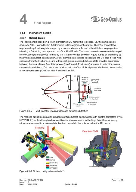
4.3.3 Instrument design<br />
4.3.3.1 Optical design<br />
The instrument is based on a 1.5 m diameter all-SiC monolithic telescope, i.e. the same size as<br />
Aeolus/ALADIN, formed by M1 & M2 mirrors in Cassegrain configuration. The PAN channel that<br />
requires a long focal length is imaged by a Korsch telescope formed with a third converging mirror<br />
following a flat folding mirror placed out of the M1-M2 axis. The other channels are separately imaged<br />
by the Cassegrain telescope formed by M1 & M2 mirrors (as shown in Figure 4.3-5), or alternately by<br />
the symmetric Korsch configuration. A first dichroïc plate is used to separate the UV-blue & Red-NIR<br />
channels from the IR channels, and within each group a second dichroïc plate provides separation<br />
between the focal planes. Four filter wheels (one for each focal plane) are used to select the narrow<br />
channels in each band. Cold stops are required in front of the IR focal planes which need to controlled<br />
at low temperatures (130 K for MWIR and 50 K for TIR).<br />
M2<br />
Doc. No: GOC-ASG-RP-002 Page 4-33<br />
Issue: 2<br />
Date: 13.05.2009 Astrium GmbH<br />
M1<br />
M3<br />
PAN high resolution<br />
detector<br />
SW/MW IR<br />
detector &<br />
filter wheel<br />
Figure 4.3-5: Multi-spectral imaging telescope optical architecture<br />
Field correction<br />
& focal length<br />
adjustment<br />
TIR detector<br />
& filter wheel<br />
UV-Blue detector<br />
& filter wheel<br />
Red-NIR detector<br />
& filter wheel<br />
The retained optical combination is based on three Korsch combinations with dioptric correctors (PAN,<br />
UV-VNIR, IR) for focal length adjustment & aberration correction in the large FoV. Several folding<br />
mirrors are required to accommodate the five channels in the volume below the M1 mirror.<br />
From M2<br />
TIR<br />
MWIR<br />
PANCHRO<br />
RED-NIR<br />
UV-BLUE<br />
Figure 4.3-6: Optical configuration (after M2)<br />
View from SVM