4 Final Report - Emits - ESA
4 Final Report - Emits - ESA
4 Final Report - Emits - ESA

Create successful ePaper yourself
Turn your PDF publications into a flip-book with our unique Google optimized e-Paper software.
4 <strong>Final</strong><br />
<strong>Report</strong><br />
S-Bd<br />
Antenna<br />
Instrument<br />
X 3500 mm<br />
Y 2300 mm<br />
Z 2300 mm<br />
S/C Body<br />
X 2450 mm<br />
Y 2600 mm<br />
Z 2200 mm<br />
PDT<br />
Antenna<br />
Space<br />
Environment<br />
Sensor<br />
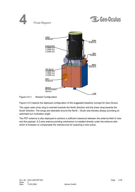
Figure 4.5-1: Stowed Configuration<br />
S-Bd<br />
Antenna<br />
Star<br />
Tracker<br />
IRES<br />
Sensors<br />
Figure 4.5-2 depicts the deployed configuration of the suggested baseline concept for Geo-Oculus.<br />
The upper solar array wing is oriented towards the North direction and the lower wing towards the<br />
South direction. The wings are steerable around the North – South axis thereby always providing an<br />
optimised sun inclination angle.<br />
The PDT antenna is also deployed to achieve a sufficient clearance between the antenna field of view<br />
and the payload. A 2-axis antenna pointing mechanism is installed directly under the antenna dish<br />
which is foreseen to compensate the manoeuvres for acquiring a new scene.<br />
Doc. No: GOC-ASG-RP-002 Page 4-49<br />
Issue: 2<br />
Date: 13.05.2009 Astrium GmbH<br />
LAE