Broaching - Horn USA, Inc.
Broaching - Horn USA, Inc.
Broaching - Horn USA, Inc.

Create successful ePaper yourself
Turn your PDF publications into a flip-book with our unique Google optimized e-Paper software.
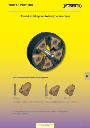
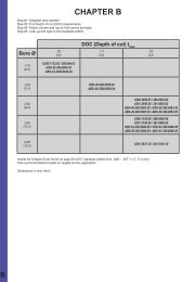
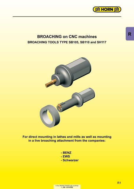
BROACHING on CNC machines<br />
BROACHING TOOLS TYPE SB105, SB110 and SH117<br />
For direct mounting in lathes and mills as well as mounting<br />
in a live broaching attachment from the companies:<br />
- BENZ<br />
- EWS<br />
- Schwarzer<br />
In the UNITED STATES call us toll free<br />
1 - 888 - 818 HORN<br />
R1<br />
R
R<br />
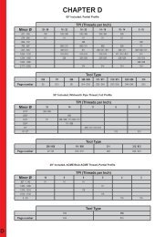
Keyway Width<br />
<strong>Inc</strong>h<br />
Bore Ø from<br />
.236'' .354" .551" .625" .669" .866" 1.181" 1.496" 1.496"<br />
1/16 NU105<br />
3/32 NU105<br />
1/8 NU105 SU117 SU117<br />
5/32 NU105 NU110 SU117 SU117<br />
3/16 NU110 SU117 SU117<br />
1/4 SU117<br />
9/32 SU117<br />
5/16 SU117<br />
3/8 SU117<br />
7/16 SU117<br />
1/2 SU117<br />
> 1/2 SU117<br />
Keyway Width<br />
MM<br />
Hexagon SW<br />
MM<br />
Bore Ø from<br />
6 mm 6.5 mm 9 mm 14 mm 17 mm 22 mm 27 mm 30 mm 38 mm 65 mm<br />
2.0 N105<br />
3.0 N105 S117<br />
4.0 N105 N110 S117<br />
5.0 N110 S117 S117<br />
6.0 S117<br />
7.0 S117<br />
8.0 S117<br />
10.0 S117<br />
12.0 S117<br />
> 12.0 S117<br />
Pilot Ø equals<br />
SW SW+0.1 SW+0.2<br />
2.5 - 2.9 N105<br />
2.9 - 3.5 N105<br />
3.5 - 4.0 N105<br />
4.0 - 4.5 N105<br />
4.5 - 5.0 N105<br />
5.0 - 6.0 N105<br />
8.0 - 10.0 N105<br />
10.0 - 14.0 N110<br />
14.0 - 16.5 N110<br />
16.5 - 18.0 N110<br />
Special tools upon request<br />
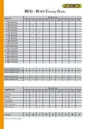
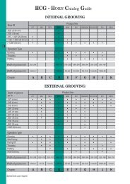
HCG - HORN Catalog Guide<br />
HEXAGON BROACHING<br />
KEYWAY BROACHING<br />
Torx<br />
MM<br />
TORX BROACHING<br />
Pilot Ø equals<br />
2.41 2.85 3.24 4.03<br />
T15 N105<br />
T20 N105<br />
T25 N105<br />
T30 N105
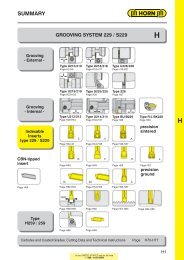
SUMMARY<br />
BROACHING 105 / 110 / 117<br />
Toolholder<br />
Type 105 / 110<br />
Insert<br />
Type 105 / 110<br />
Toolholder<br />
Type 117<br />
Insert<br />
Type 117<br />
Technical<br />
Instructions<br />
Page R4-R8<br />
Keyway<br />
Keyway<br />
Page R10-R13<br />
Chamfer<br />
Page R14-R17 Page R18<br />
Page R22-R27<br />
Chamfer<br />
Page R28-R31 Page R32<br />
Page R33-R40<br />
In the UNITED STATES call us toll free<br />
1 - 888 - 818 HORN<br />
Hexagon Torx<br />
Page R19 Page R20<br />
R<br />
R3<br />
R
R<br />
BROACHING<br />
TOOLHOLDER Type SBU105<br />
Bore Ø from .236″<br />
Part number d l 1 l 2 D min<br />
SBU105.0750.1.01 .750 2.375 1.575 .236<br />
SBU105.1000.1.01 1.000 2.375 1.575 .236<br />
Further sizes upon request Dimensions in inch<br />
Spare parts<br />
Toolholder Screw TORX PLUS ® Wrench<br />
SBU105.... 6.075T15P T15PQ<br />
R4<br />
In the UNITED STATES call us toll free<br />
1 - 888 - 818 HORN<br />
for use with Insert<br />
Type<br />
N105<br />
NU105
BROACHING<br />
TOOLHOLDER Type SB105<br />
Bore Ø from .236″ (6.0 mm)<br />
Part number d l 1 l 2 D min<br />
SB105.0020.1.01 20 60 40 6<br />
SB105.0022.1.01 22 60 40 6<br />
SB105.0025.1.01 25 60 40 6<br />
Further sizes upon request Dimensions in mm<br />
Spare parts<br />
Toolholder Screw TORX PLUS ® Wrench<br />
SB105.002... 6.075T15P T15PQ<br />
In the UNITED STATES call us toll free<br />
1 - 888 - 818 HORN<br />
for use with Insert<br />
Type N105<br />
NU105<br />
R5<br />
R
R<br />
BROACHING<br />
TOOLHOLDER Type SB105<br />
Bore Ø from .236″ (6.0 mm)<br />
only usable for broaching devices EWS-Slot and BENZ LinA<br />
Part number d l 1 l 2 D min<br />
SB105.0016.E1.01 16 51 30 6<br />
Further sizes for other device interfaces upon request Dimensions in mm<br />
Spare parts<br />
Toolholder Screw TORX PLUS ® Wrench<br />
SB105.0016.E1.01 6.075T15P T15PQ<br />
R6<br />
In the UNITED STATES call us toll free<br />
1 - 888 - 818 HORN<br />
for use with Insert<br />
Type<br />
N105<br />
NU105
BROACHING<br />
TOOLHOLDER Type B105<br />
Bore Ø from .236″ (6.0 mm)<br />
for broaching device Schwarzer<br />
Part number d l 1 l 2 D min<br />
B105.0012.0220 12 40 25 6<br />
Further sizes for other device interfaces upon request Dimensions in mm<br />
Spare parts<br />
Toolholder Screw TORX PLUS ® Wrench<br />
B105.0012.0220 6.075T15P T15PQ<br />
In the UNITED STATES call us toll free<br />
1 - 888 - 818 HORN<br />
for use with Insert<br />
Type N105<br />
NU105<br />
R7<br />
R
R<br />
BROACHING<br />
TOOLHOLDER Type SB105<br />
Bore Ø from .236″ (6.0 mm)<br />
for broaching device Schwarzer "2in1"<br />
Part number d l 1 l 2 D min<br />
SB105.0015.S1.01 15 52 34 6<br />
Further sizes for other device interfaces upon request Dimensions in mm<br />
Spare parts<br />
Toolholder Screw TORX PLUS ® Wrench<br />
SB105.0015.S1.01 6.075T15P T15PQ<br />
R8<br />
In the UNITED STATES call us toll free<br />
1 - 888 - 818 HORN<br />
for use with Insert<br />
Type<br />
N105<br />
NU105
BROACHING<br />
UPON REQUEST<br />
External serration broaching for finish machining on<br />
CNC turning machines.<br />
Machine MUST have C-Axis for this application!<br />
In the UNITED STATES call us toll free<br />
1 - 888 - 818 HORN<br />
R9<br />
R
R<br />
BROACHING<br />
TOOLHOLDER Type SBU110<br />
Bore Ø from .354″<br />
Part number d l 1 l 2 D min<br />
SBU110.0750.1.02 .750 3.200 1.575 .354<br />
SBU110.1000.1.02 1.000 3.200 1.575 .354<br />
SBU110.1250.1.02 1.250 3.200 1.575 .354<br />
Further sizes upon request Dimensions in inch<br />
Spare parts<br />
Toolholder Screw TORX PLUS ® Wrench<br />
SBU110.... 6.075T15P T15PQ<br />
R10<br />
In the UNITED STATES call us toll free<br />
1 - 888 - 818 HORN<br />
for use with Insert<br />
Type<br />
N110<br />
NU110
BROACHING<br />
TOOLHOLDER Type SB110<br />
Bore Ø from .354″ (9.0 mm)<br />
Part number d l 1 l 2 D min<br />
SB110.0020.1.02 20 81 40 9<br />
SB110.0025.1.02 25 81 40 9<br />
SB110.0032.1.02 32 81 40 9<br />
Further sizes upon request Dimensions in mm<br />
Spare parts<br />
Toolholder Screw TORX PLUS ® Wrench<br />
SB110.00... 6.075T15P T15PQ<br />
In the UNITED STATES call us toll free<br />
1 - 888 - 818 HORN<br />
for use with Insert<br />
Type N110<br />
NU110<br />
R11<br />
R
R<br />
BROACHING<br />
TOOLHOLDER Type SB110<br />
Bore Ø from .354″ (9.0 mm)<br />
only usable for broaching devices EWS-Slot and BENZ LinA<br />
Part number d l 1 l 2 D min<br />
SB110.0016.E1.02 16 72 30 9<br />
Further sizes for other device interfaces upon request Dimensions in mm<br />
Spare parts<br />
Toolholder Screw TORX PLUS ® Wrench<br />
SB110.0016.E1.02 6.075T15P T15PQ<br />
R12<br />
In the UNITED STATES call us toll free<br />
1 - 888 - 818 HORN<br />
for use with Insert<br />
Type<br />
N110<br />
NU110
BROACHING<br />
TOOLHOLDER Type SB110<br />
Bore Ø from .354″ (9.0 mm)<br />
for broaching device Schwarzer "2in1"<br />
Part number d l 1 l 2 D min<br />
SB110.0015.S1.02 15 66 34 9<br />
Further sizes for other device interfaces upon request Dimensions in mm<br />
Spare parts<br />
Toolholder Screw TORX PLUS ® Wrench<br />
SB110.0015.S1.02 6.075T15P T15PQ<br />
In the UNITED STATES call us toll free<br />
1 - 888 - 818 HORN<br />
for use with Insert<br />
Type N110<br />
NU110<br />
R13<br />
R
R<br />
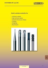
BROACHING<br />
INSERT type NU105/NU110<br />
Bore Ø from<br />
Part number Fractional<br />
size<br />
NU105.0625.04.01 1/16'' .0635<br />
.236'' (6.0 mm)<br />
w r l 5 l 2 l 3 D min<br />
1.181 .472 .709 .236<br />
NU105.0937.04.01 3/32'' .0948 1.181 .472 .709 .256 ▲<br />
.004<br />
NU105.1250.04.01 1/8'' .1260 1.378 .591 .906 .256 ▲<br />
NU105.1562.04.01 5/32'' .1572 1.378 .591 .906 .256 ▲<br />
NU110.1562.08.04 5/32'' .1572<br />
2.362 .984 1.339<br />
NU110.1562.08.07 5/32'' .1572 2.953 1.575 2.126 ▲<br />
.008<br />
.354<br />
NU110.1875.08.04 3/16'' .1885 2.362 .984 1.339 ▲<br />
NU110.1875.08.07 3/16'' .1885 2.953 1.575 2.126 ▲<br />
▲ on stock Δ 4 weeks P ●<br />
● main recommendation M ●<br />
ο alternative recommendation K ●<br />
Toolholder<br />
SB105<br />
SBU105<br />
SB110<br />
SBU110<br />
███ uncoatet grades S<br />
███ coatet grades N ●<br />
███ brazed/Cermet H<br />
In the UNITED STATES call us toll free<br />
1 - 888 - 818 HORN<br />
for use with Toolholder<br />
type<br />
SB105<br />
SB110<br />
SBU105<br />
SBU110<br />
Dimensions in mm Carbide Grades<br />
R14<br />
THIS PAGE HAS BEEN ELECTRONICALLY MODIFIED<br />
Keyways according to<br />
<strong>Inc</strong>h Standards<br />
MG12<br />
TA45<br />
▲<br />
▲<br />
TI25
BROACHING<br />
INSERT type N105/N110<br />
Tolerance grade P9<br />
Bore Ø from<br />
Part number Dimensions of groove<br />
DIN<br />
Width P9 D min t<br />
.236" (6.0 mm)<br />
w r l 5 l 2 l 3<br />
N105.0198.01.01 2 6 1.1 1.98 30 12 18 6.0<br />
▲<br />
N105.0298.01.01 3 8 1.5 2.98 0.1 30 12 18 6.5 ▲<br />
N105.0397.01.01 4 10 1.9 3.98 35 15 23 6.5 ▲<br />
N110.0397.02.04 4 10 1.9 3.98 60 25 34<br />
▲<br />
N110.0397.02.07<br />
N110.0497.02.04<br />
4<br />
5<br />
10<br />
12<br />
1.9<br />
2.4<br />
3.98<br />
4.98<br />
0.2<br />
75<br />
60<br />
40<br />
25<br />
49<br />
34<br />
9.0<br />
▲<br />
▲<br />
N110.0497.02.07 5 12 2.4 4.98 75 40 49 ▲<br />
▲ on stock Δ 4 weeks P ●<br />
● main recommendation M ●<br />
ο alternative recommendation K ●<br />
███ uncoatet grades S<br />
███ coatet grades N ●<br />
usable from Ø<br />
Toolholder<br />
SB105 /<br />
SBU105<br />
SB110 /<br />
SBU110<br />
███ brazed/Cermet H<br />
In the UNITED STATES call us toll free<br />
1 - 888 - 818 HORN<br />
for use with Toolholder<br />
type<br />
SB105<br />
SB110<br />
SBU105<br />
SBU110<br />
Keyways according to DIN138<br />
Dimensions in mm Carbide Grades<br />
MG12<br />
TA45<br />
TI25<br />
R15<br />
R
R<br />
BROACHING<br />
INSERT type N105/N110<br />
Tolerance grade JS9<br />
Bore Ø from<br />
Part number Dimensions of groove<br />
DIN<br />
Width JS9 D min t<br />
.236" (6.0 mm)<br />
w r l 5 l 2 l 3<br />
N105.0200.01.01 2 6 1.1 2 0.1 30 12 18 6.0<br />
▲<br />
N105.0300.01.01 3 8 1.5 3 0.1 30 12 18 6.5 ▲<br />
N105.0400.01.01 4 10 1.9 4 0.1 35 15 23 6.5 ▲<br />
N105.0400.02.01 4 10 1.9 4 0.2 35 15 23 6.5 ▲<br />
N110.0400.02.04 4 10 1.9 4<br />
60 25 34<br />
▲<br />
N110.0400.02.07<br />
N110.0500.02.04<br />
4<br />
5<br />
10<br />
12<br />
1.9<br />
2.4<br />
4<br />
5<br />
0.2<br />
75<br />
60<br />
40<br />
25<br />
49<br />
34<br />
9.0<br />
▲<br />
▲<br />
N110.0500.02.07 5 12 2.4 5 75 40 49 ▲<br />
▲ on stock Δ 4 weeks P ●<br />
● main recommendation M ●<br />
ο alternative recommendation K ●<br />
███ uncoatet grades S<br />
███ coatet grades N ●<br />
usable from Ø<br />
Toolholder<br />
SB105 /<br />
SBU105<br />
SB110 /<br />
SBU110<br />
███ brazed/Cermet H<br />
In the UNITED STATES call us toll free<br />
1 - 888 - 818 HORN<br />
for use with Toolholder<br />
Dimensions in mm Carbide Grades<br />
R16<br />
type<br />
SB105<br />
SB110<br />
SBU105<br />
SBU110<br />
Keyways according to DIN138<br />
MG12<br />
TA45<br />
TI25
BROACHING<br />
INSERT type N105/N110<br />
Tolerance grade C11<br />
Bore Ø from<br />
Part number Dimensions of groove<br />
DIN<br />
Width C11 D min t<br />
.236" (6.0 mm)<br />
w r l 5 l 2 l 3<br />
N105.0210.2.08 2 8.0 1.0 2.11 0.35<br />
18 6.0<br />
▲<br />
N105.0310.2.10<br />
N105.0310.2.13<br />
3<br />
3<br />
10.0<br />
13.0<br />
1.8<br />
1.8<br />
3.11<br />
3.11<br />
0.35<br />
0.50<br />
30 12<br />
18<br />
18<br />
6.5<br />
6.5<br />
▲<br />
▲<br />
N105.0410.2.16 4 16.0 2.0 4.13 0.50 23 6.5 ▲<br />
N110.0410.05.04 4 9.0 2.0 4.13<br />
60 25 34<br />
▲<br />
N110.0410.05.07<br />
N110.0510.05.04<br />
4<br />
5<br />
9.0<br />
9.0<br />
2.0<br />
-<br />
4.13<br />
5.13<br />
0.50<br />
75<br />
60<br />
40<br />
25<br />
49<br />
34<br />
9.0<br />
▲<br />
▲<br />
N110.0510.05.07 5 9.0 - 5.13 75 40 49 ▲<br />
▲ on stock Δ 4 weeks P ●<br />
● main recommendation M ●<br />
ο alternative recommendation K ●<br />
███ uncoatet grades S<br />
███ coatet grades N ●<br />
usable from Ø<br />
Toolholder<br />
SB105 /<br />
SBU105<br />
SB110 /<br />
SBU110<br />
███ brazed/Cermet H<br />
In the UNITED STATES call us toll free<br />
1 - 888 - 818 HORN<br />
for use with Toolholder<br />
type<br />
SB105<br />
SB110<br />
SBU105<br />
SBU110<br />
Keyways according to DIN138<br />
Dimensions in mm Carbide Grades<br />
MG12<br />
TA45<br />
TI25<br />
R17<br />
R
R<br />
BROACHING - CHAMFERING<br />
INSERT type N105/N110<br />
Bore Ø from<br />
.236" (6.0 mm)<br />
Part number Chamfer w w 1 l 5 l 2 l 3 usable from Ø Toolholder<br />
N105.4545.2.6<br />
N105.4545.3.6<br />
45° 4.5 1<br />
30<br />
35<br />
12<br />
20<br />
18<br />
23<br />
6<br />
SB105 /<br />
SBU105<br />
▲<br />
▲<br />
N110.4545.4.9<br />
N110.4545.7.9<br />
45° 6.3 2<br />
60<br />
75<br />
25<br />
40<br />
34<br />
49<br />
9<br />
SB110<br />
SBU110<br />
▲<br />
▲<br />
▲ on stock Δ 4 weeks P ●<br />
● main recommendation M ●<br />
ο alternative recommendation K ●<br />
███ uncoatet grades S<br />
███ coatet grades N ●<br />
███ brazed/Cermet H<br />
In the UNITED STATES call us toll free<br />
1 - 888 - 818 HORN<br />
for use with Toolholder<br />
type<br />
Chamfering<br />
Dimensions in mm Carbide Grades<br />
R18<br />
SB105<br />
SB110<br />
SBU105<br />
SBU110<br />
MG12<br />
TA45<br />
TI25
BROACHING - HEXAGON SOCKET<br />
INSERT Type N105/N110<br />
Hexagon socket from SW 2.5<br />
Part number SW r l 2 l 3 l 5 Pilot Ø X Toolholder<br />
N105.SW25.25.01 2.5-2.9 0.05 4.0 13 25 SW<br />
N105.SW30.30.01 2.9-3.5 0.05 4.5 13 25 SW ▲<br />
N105.SW35.35.01 3.5-4.0 0.05 5.5 13 25 SW ▲<br />
N105.SW40.40.01 4.0-4.5 0.10 6.0 13 25 SW 1.0 SB105<br />
▲<br />
N105.SW45.45.01 4.5-5.0 0.10 7.0 13 25 SW ▲<br />
N105.SW56.56.01 5.0-8.0 0.10 9.0 13 25 SW+0.1 ▲<br />
N105.SW80.80.01 8.0-10.0 0.10 12.0 18 30 SW+0.1 ▲<br />
N110.SW14.14.03 10.0-14.0 0.20 20.0 29 55 SW+0.1 1.5 SB110 Δ<br />
N110.SW16.16.04<br />
14.0-16.5/<br />
16.5-18.0<br />
0.20 25.0 29 55<br />
SW+0.1/<br />
SW+0.2<br />
Dimensions in mm Carbide grades<br />
MG12<br />
TA45<br />
2.0 SB110 Δ<br />
▲ on stock Δ 4 weeks P ●<br />
● main recommendation M ●<br />
ο alternative recommendation K ●<br />
███ uncoated grades S ●<br />
███ coated grades N ●<br />
███ brazed/Cermet H<br />
In the UNITED STATES call us toll free<br />
1 - 888 - 818 HORN<br />
for use with Toolholder<br />
Type<br />
SB105<br />
SB110<br />
SBU105<br />
SBU110<br />
Hexagon socket<br />
▲<br />
TI25<br />
R19<br />
R
R<br />
BROACHING - TORX<br />
INSERT Type N105<br />
Torx from T15<br />
Part number Torx l 2 l 3 l 5 Pilot Ø Toolholder<br />
N105.TX15.24.03 T15 4<br />
2.41<br />
Δ<br />
N105.TX20.28.03 T20 4<br />
23 35<br />
2.85<br />
SB105<br />
Δ<br />
N105.TX25.32.03 T25 5 3.24 Δ<br />
N105.TX30.40.03 T30 5 4.03 Δ<br />
▲ on stock Δ 4 weeks P ●<br />
● main recommendation M ●<br />
ο alternative recommendation K ●<br />
███ uncoated grades S ●<br />
███ coated grades N ●<br />
███ brazed/Cermet H<br />
Dimensions in mm Carbide grades<br />
R20<br />
In the UNITED STATES call us toll free<br />
1 - 888 - 818 HORN<br />
for use with Toolholder<br />
Type<br />
SB105<br />
SBU105<br />
Torx<br />
MG12<br />
TA45<br />
TI25
SUMMARY - BROACHING TOOLS<br />
Type SB105/SB110 -<br />
Holder can be located directly in the turret and m/c spindle<br />
Dimensions DIN<br />
Width<br />
Tolerance grade<br />
D min<br />
t<br />
<strong>Broaching</strong> Chamfering<br />
Inserts l 2 Toolholder Inserts Toolholder<br />
2 C11 8 1,0 N105.0210.2.08 12<br />
3<br />
3<br />
C11<br />
C11<br />
10<br />
13<br />
1,8<br />
1,8<br />
N105.0310.2.10<br />
N105.0310.2.13<br />
12<br />
12<br />
SB105.0020.1.01<br />
SB105.0025.1.01<br />
N105.4545.2.6<br />
SB105.0020.1.01<br />
SB105.0025.1.01<br />
4 C11 16 2,0 N105.0410.2.16 12<br />
4 C11 16 2,0 N110.0410.05.04 25 SB110.0025.1.02 N110.4545.4.9 SB110.0025.1.02<br />
4 C11 16 2,0 N110.0410.05.07 40 SB110.0032.1.02 N110.4545.7.9 SB110.0032.1.02<br />
5 C11 - - N110.0510.05.04 25 SB110.0025.1.02 N110.4545.4.9 SB110.0025.1.02<br />
5 C11 - - N110.0510.05.07 40 SB110.0032.1.02 N110.4545.7.9 SB110.0032.1.02<br />
2<br />
3<br />
P9<br />
P9<br />
6<br />
8<br />
1,1<br />
1,5<br />
N105.0198.01.01<br />
N105.0298.01.01<br />
12<br />
12 SB105.0020.1.01<br />
N105.4545.2.6 SB105.0020.1.01<br />
4 P9 10 1,9 N105.0397.01.01 15 SB105.0025.1.01 N105.4545.3.6 SB105.0025.1.01<br />
4 P9 10 1,9 N110.0397.02.04 25<br />
N110.4545.4.9<br />
4 P9 10 1,9 N110.0397.02.07 40 SB110.0025.1.02 N110.4545.7.9 SB110.0025.1.02<br />
5 P9 12 2,4 N110.0497.02.04 25 SB110.0032.1.02 N110.4545.4.9 SB110.0032.1.02<br />
5 P9 12 2,4 N110.0497.02.07 40 N110.4545.7.9<br />
2 JS9 6 1,1 N105.0200.01.01 12<br />
3 JS9 8 1,5 N105.0300.01.01 12 SB105.0020.1.01 N105.4545.2.6 SB105.0020.1.01<br />
4 JS9 10 1,9 N105.0400.01.01 12 SB105.0025.1.01<br />
SB105.0025.1.01<br />
4 JS9 10 1,9 N105.0400.02.01 15 N105.4545.3.6<br />
4 JS9 10 1,9 N110.0400.02.04 25<br />
N110.4545.4.9<br />
4 JS9 10 1,9 N110.0400.02.07 40 SB110.0025.1.02 N110.4545.7.9 SB110.0025.1.02<br />
5 JS9 12 2,4 N110.0500.02.04 25 SB110.0032.1.02 N110.4545.4.9 SB110.0032.1.02<br />
5 JS9 12 2,4 N110.0500.02.07 40 N110.4545.7.9<br />
In the UNITED STATES call us toll free<br />
1 - 888 - 818 HORN<br />
R21<br />
R
R<br />
BROACHING<br />
TOOLHOLDER Type SHU117<br />
Bore Ø from .551″<br />
Part number d h l l 1 l 2 D min f 1 Form<br />
SHU117.1410.1.3.08 1.000 .921 1.260 2.835 .787 .551 .378 G<br />
SHU117.1410.1.08<br />
1.654 3.228 1.181<br />
SHU117.1410.2.08 1.000 .921 2.047 3.622 1.575<br />
Further sizes upon request Dimensions in inch<br />
Spare parts<br />
Toolholder Screw TORX PLUS ® Wrench<br />
SHU117....10 4.09T15P T15PQ<br />
SHU117....16 5.12T20P T20PQ<br />
SHU117.1410....08 030.3509.T15P T15PQ<br />
.551 .378 F<br />
SHU117.0610.1.10 1.000 .921 1.898 3.472 1.575 .625 .425 A1<br />
SHU117.0100.1.10<br />
1.976 3.551 1.575 .669 .374<br />
SHU117.0100.2.10<br />
SHU117.0910.1.10<br />
1.000 .921<br />
2.567<br />
2.433<br />
4.142<br />
4.008<br />
2.165<br />
1.969<br />
.669<br />
.866<br />
.374<br />
.472<br />
SHU117.0910.2.10 3.220 4.795 2.756 .866 .472<br />
SHU117.1000.1.10<br />
2.433 4.008 1.969<br />
SHU117.1000.2.10<br />
1.000 .921<br />
3.220 4.795 2.756<br />
SHU117.0125.1.16<br />
2.433 4.008 1.969<br />
SHU117.0125.2.16 1.250 1.171 3.374 4.949 2.953<br />
SHU117.0125.3.16 4.358 6.720 3.937<br />
SHU117.1250.1.16<br />
2.433 4.008 1.969<br />
SHU117.1250.2.16 1.250 1.171 3.374 4.949 2.953<br />
SHU117.1250.3.16 4.358 6.720 3.937<br />
R22<br />
In the UNITED STATES call us toll free<br />
1 - 888 - 818 HORN<br />
for use with Insert<br />
Type<br />
S117<br />
SU117<br />
A<br />
.866 .472 B<br />
1.181 .659 C<br />
1.496 .866 D
BROACHING<br />
TOOLHOLDER Type SH117<br />
Bore Ø from .551″ (14.0 mm)<br />
Part number d h l l 1 l 2 D min f 1 Form<br />
SH117.1425.1.3.08 25 23 32 72 20 14 9.6 G<br />
SH117.1425.1.08<br />
42 82 30<br />
SH117.1425.2.08<br />
25 23<br />
52 92 40<br />
SH117.1725.1.10<br />
50 90 40<br />
SH117.1725.2.10<br />
25 23<br />
65 105 55<br />
SH117.0025.1.10<br />
60 100 50<br />
SH117.0025.2.10<br />
25 23<br />
80 120 70<br />
SH117.3032.1.16<br />
60 100 50<br />
SH117.3032.2.16 32 30 85 125 75<br />
SH117.3032.3.16 110 170 100<br />
SH117.0032.1.16<br />
60 100 50<br />
SH117.0032.2.16 32 30 85 125 75<br />
SH117.0032.3.16 110 170 100<br />
SH117.4032.1.16<br />
62 122 50<br />
SH117.4032.2.16 32 30 87 147 75<br />
SH117.4032.3.16 112 172 100<br />
Further sizes upon request Dimensions in mm<br />
Spare parts<br />
Toolholder Screw TORX PLUS ® Wrench<br />
SH117....10 4.09T15P T15PQ<br />
SH117....16 5.12T20P T20PQ<br />
SH117.1425....08 030.3509.T15P T15PQ<br />
In the UNITED STATES call us toll free<br />
1 - 888 - 818 HORN<br />
for use with Insert<br />
Type S117<br />
SU117<br />
14 9.6 F<br />
17 9.5 A<br />
22 12.0 B<br />
30 16.5 C<br />
38 22.0 D<br />
40 21.5 E<br />
R23<br />
R
BROACHING<br />
TOOLHOLDER Type SH117<br />
Bore Ø from .551″ (14.0 mm)<br />
only usable for broaching devices EWS-Slot and BENZ LinA<br />
Part number d l l 1 l 2 D min f 1 Form<br />
SH117.1416.E1.08 16 41 71 30 14 9.6 F<br />
SH117.1716.E1.10<br />
41 71 30<br />
SH117.1716.E2.10<br />
16<br />
51 81 40<br />
SH117.0016.E1.10<br />
41 71 30<br />
SH117.0016.E2.10<br />
16<br />
51 81 40<br />
Further sizes for other device interfaces upon request Dimensions in mm<br />
Spare parts<br />
Toolholder Screw TORX PLUS ® Wrench<br />
SH117....10 4.09T15P T15PQ<br />
SH117.1416.E1.08 030.3509.T15P T15PQ<br />
In the UNITED STATES call us toll free<br />
1 - 888 - 818 HORN<br />
for use with Insert<br />
Type S117<br />
SU117<br />
17 9.5 A<br />
22 12.0 B<br />
R25<br />
R
R<br />
BROACHING<br />
TOOLHOLDER Type H117<br />
Bore Ø from .669″ (17.0 mm)<br />
for broaching device Schwarzer<br />
Part number d l l 1 l 2 D min f 1 a Form<br />
H117.1712.1439<br />
33 58 25<br />
H117.1712.1407<br />
12<br />
43 68 35<br />
H117.2212.1441<br />
33 58 25<br />
H117.2212.1442<br />
12<br />
43 68 35<br />
H117.3012.1440<br />
33 58 25<br />
H117.3012.1419<br />
12<br />
43 68 35<br />
Further sizes for other<br />
device interfaces upon request<br />
Spare parts<br />
Toolholder Screw TORX PLUS ® Wrench<br />
H117....1407/1439/1441/1442 4.09T15P T15PQ<br />
H117.3012.1419/1440 5.12T20P T20PQ<br />
R26<br />
In the UNITED STATES call us toll free<br />
1 - 888 - 818 HORN<br />
for use with Insert<br />
Type<br />
S117<br />
SU117<br />
17 9.5 16.00 A<br />
22 12.0 20.75 B<br />
30 16.5 28.50 C<br />
Dimensions in mm
BROACHING<br />
TOOLHOLDER Type SH117<br />
with through coolant supply<br />
Bore Ø from .551″ (14.0 mm)<br />
for broaching device Schwarzer "2in1"<br />
Part number d l l 1 l 2 D min f 1 a Form<br />
SH117.0932.S.08 15 37 70 32<br />
SH117.1412.S1.08 12 33 58 25<br />
SH117.1412.S2.08 12 43 68 35<br />
Further sizes for other device interfaces upon request Dimensions in mm<br />
Spare parts<br />
Toolholder Screw TORX PLUS ® Wrench<br />
SH117....08 030.3509.T15P T15PQ<br />
SH117....10 4.09T15P T15PQ<br />
SH117.15...16 5.12T20P T20PQ<br />
14 9.6 12.8 F<br />
SH117.0932.S.10 15 37 70 32 17 9.5 16.0 A<br />
SH117.1532.S.10 15 37 70 32 22 12.0 20.0 B<br />
SH117.1538.S.16<br />
43 76 38<br />
SH117.1544.S.16<br />
15<br />
49 82 44<br />
In the UNITED STATES call us toll free<br />
1 - 888 - 818 HORN<br />
THIS PAGE HAS BEEN ELECTRONICALLY MODIFIED<br />
for use with Insert<br />
Type S117<br />
SU117<br />
30 15.0 24.0 C<br />
R27<br />
R
THIS PAGE HAS BEEN ELECTRONICALLY MODIFIED
BROACHING<br />
INSERT Type S117<br />
Tolerance grade C11<br />
Bore Ø from<br />
Depth of groove up to<br />
Part number Nw w r E l t max f Form<br />
S117.0410.05.08 4 4.12 0.50 4 13 2.1 6.0 F ▲<br />
S117.0610.22 6 6.12 0.85<br />
Dimensions in mm Carbide grades<br />
Note:<br />
The insert form must correspond to the holder form.<br />
E.g.: Form A Toolholder = Form A Insert<br />
2.6<br />
MG12<br />
TA45<br />
TN35<br />
TI25<br />
▲ ▲<br />
S117.0710.27 7 7.13 0.85 3 16 3.3 8.0 B<br />
▲ Δ<br />
S117.0810.32 8 8.13 1.05 3.4 ▲ ▲<br />
S117.1014.40 10 10.13 1.05<br />
.551″ (14.0 mm)<br />
.335″ (8.5 mm)<br />
4.2<br />
▲ Δ<br />
S117.1214.50<br />
S117.1614.70<br />
12<br />
16<br />
12.15<br />
12.15<br />
1.35<br />
1.75<br />
6 21<br />
5.1<br />
6.6<br />
11.2 D<br />
▲<br />
Δ<br />
Δ<br />
S117.2414.100 24 12.15 2.25 8.5 Δ<br />
▲ on stock Δ 4 weeks P ● ●<br />
● main recommendation M ● ●<br />
ο alternative recommendation K ● ●<br />
███ uncoated grades S ● ●<br />
███ coated grades N ● ●<br />
███ brazed/Cermet H<br />
In the UNITED STATES call us toll free<br />
1 - 888 - 818 HORN<br />
for use with Toolholder<br />
Type<br />
SH117<br />
SHM117<br />
SHU117<br />
Keyways according to<br />
DIN138<br />
R29<br />
R
R<br />
BROACHING<br />
INSERT Type S117<br />
Tolerance grade P9<br />
Bore Ø from<br />
Depth of groove up to<br />
Part number Nw w r E l t max f Form<br />
S117.0298.01.08 3 2.99 0.12 4 13.0 2.0 6.0 G ▲<br />
S117.0397.01.08 4 3.98 0.12<br />
2.1<br />
▲<br />
S117.0497.02.08 5 4.98 0.20<br />
4 13.0<br />
2.7<br />
6.0 F<br />
▲<br />
S117.0497.02.10 5 4.98<br />
2.7<br />
▲<br />
S117.0597.02.10 6 5.98<br />
0.20 3 14.5<br />
3.4<br />
6.5 A<br />
▲<br />
S117.0796.02.10 8 7.98 0.20 3 16.0 4.1 8.0 B ▲<br />
S117.0996.03.14 10 9.98 0.30 6 21.0 4.2 11.2 C ▲<br />
S117.1196.03.14 12 11.97 0.30 6 21.0 5.7 11.2 D ▲<br />
S117.1396.03.16 14 13.97 0.30 6 21.0 6.8 11.2 E ▲<br />
▲ on stock Δ 4 weeks P ●<br />
● main recommendation M ●<br />
ο alternative recommendation K ●<br />
███ uncoated grades S ●<br />
███ coated grades N ●<br />
███ brazed/Cermet H<br />
Dimensions in mm Carbide grades<br />
Note:<br />
The insert form must correspond to the holder form.<br />
E.g.: Form A Toolholder = Form A Insert<br />
R30<br />
.551″ (14.0 mm)<br />
.268″ (6.8 mm)<br />
In the UNITED STATES call us toll free<br />
1 - 888 - 818 HORN<br />
for use with Toolholder<br />
Type<br />
SH117<br />
SHM117<br />
SHU117<br />
Keyways according to<br />
DIN138<br />
MG12<br />
TA45<br />
TN35<br />
TI25
BROACHING<br />
INSERT Type S117<br />
Tolerance grade JS9<br />
Bore Ø from<br />
Depth of groove up to<br />
Part number Nw w r E l t max f Form<br />
S117.0300.01.08 3 3.01 0.12 4 13.0 2.0 6.0 G ▲<br />
S117.0400.01.08 4 4.01 0.12<br />
2.1<br />
▲<br />
S117.0500.02.08 5 5.01 0.20<br />
4 13.0<br />
2.7<br />
6.0 F<br />
▲<br />
S117.0500.02.10 5 5.01<br />
2.7<br />
▲<br />
S117.0600.02.10 6 6.01<br />
0.20 3 14.5<br />
3.4<br />
6.5 A<br />
▲<br />
S117.0800.02.10 8 8.01 0.20 3 16.0 4.1 8.0 B ▲<br />
S117.1000.03.14 10 10.01 0.30 6 21.0 4.2 11.2 C ▲<br />
S117.1200.03.14<br />
12.01 0.30<br />
5.7<br />
▲<br />
S117.1200.05.14<br />
12<br />
12.00 0.50<br />
6 21.0<br />
8.5<br />
11.2 D<br />
▲<br />
Dimensions in mm Carbide grades<br />
Note:<br />
The insert form must correspond to the holder form.<br />
E.g.: Form A Toolholder = Form A Insert<br />
.551″ (14.0 mm)<br />
.335″ (8.5 mm)<br />
S117.1400.03.16 14 14.01 0.30 6 21.0 6.8 11.2 E ▲<br />
▲ on stock Δ 4 weeks P ●<br />
● main recommendation M ●<br />
ο alternative recommendation K ●<br />
███ uncoated grades S ●<br />
███ coated grades N ●<br />
███ brazed/Cermet H<br />
In the UNITED STATES call us toll free<br />
1 - 888 - 818 HORN<br />
for use with Toolholder<br />
Type<br />
SH117<br />
SHM117<br />
SHU117<br />
Keyways according to<br />
DIN138<br />
MG12<br />
TA45<br />
TN35<br />
TI25<br />
R31<br />
R
R<br />
BROACHING-CHAMFERING<br />
INSERT Type S117<br />
Bore Ø from .551″<br />
Part number Nw w l f Form<br />
S117.2445.08 .094 .094 .512 .236 F ▲<br />
S117.1545.10 .079 .059 .630 .315 A ▲<br />
S117.3045.10 .118 .118 .630 .315 B ▲<br />
S117.6045.14 .236 .236 .827 .441 C/D ▲<br />
▲ on stock Δ 4 weeks P ●<br />
● main recommendation M ●<br />
ο alternative recommendation K ●<br />
███ uncoated grades S ●<br />
███ coated grades N ●<br />
███ brazed/Cermet H<br />
Dimensions in mm Carbide grades<br />
Note:<br />
The insert form must correspond to the holder form.<br />
E.g.: Form A Toolholder = Form A Insert<br />
R32<br />
In the UNITED STATES call us toll free<br />
1 - 888 - 818 HORN<br />
for use with Toolholder<br />
Type<br />
SH117<br />
SHM117<br />
SHU117<br />
Chamfering<br />
MG12<br />
TA45<br />
TN35<br />
TI25
SUMMARY - BROACHING TOOLS<br />
Type SH117 - Holder can be located directly in the turret and m/c spindle<br />
<strong>Broaching</strong> Chamfering<br />
Dimensions DIN<br />
Tool length l 2<br />
Inserts w Toolholder Tool length l 2 Inserts Toolholder<br />
t<br />
D min<br />
.1. .2. .3. .1. .2. .3.<br />
Tolerance grade<br />
Width<br />
6 C11 22 2,6 S117.0610.22 6,12 SH117.0025...10 50 70 S117.3045.10 SH117.0025...10 50 70<br />
7 C11 27 3,3 S117.0710.27 7,13 SH117.0025...10 50 70 S117.3045.10 SH117.0025...10 50 70<br />
8 C11 32 3,4 S117.0810.32 8,13 SH117.0025...10 50 70 S117.3045.10 SH117.0025...10 50 70<br />
10 C11 40 4,2 S117.1014.40 10,13 SH117.0032...16 50 75 100 S117.6045.14 SH117.0032...16 50 75 100<br />
12 C11 50 5,1 S117.1214.50 12,15 SH117.0032...16 50 75 100 S117.6045.14 SH117.0032...16 50 75 100<br />
16 C11 70 6,6 S117.1614.70 12,15 SH117.0032...16 50 75 100 S117.6045.14 SH117.0032...16 50 75 100<br />
24 C11 100 8,5 S117.2414.100 12,15 SH117.0032...16 50 75 100 S117.6045.14 SH117.0032...16 50 75 100<br />
5 P9 17 2,7 S117.0497.02.10 4,98 SH117.1725...10 40 55 S117.1545.10 SH117.1725...10 40 55<br />
6 P9 17 3,4 S117.0597.02.10 5,98 SH117.1725...10 40 55 S117.1545.10 SH117.1725...10 40 55<br />
In the UNITED STATES call us toll free<br />
1 - 888 - 818 HORN<br />
8 P9 22 4,1 S117.0796.02.10 7,98 SH117.0025...10 50 70 S117.3045.10 SH117.0025...10 50 70<br />
10 P9 30 4,2 S117.0996.03.14 9,98 SH117.3032...16 50 75 100 S117.6045.14 SH117.3032...16 50 75 100<br />
12 P9 38 5,7 S117.1196.03.14 11,97 SH117.0032...16 50 75 100 S117.6045.14 SH117.0032...16 50 75 100<br />
14 P9 40 6,8 S117.1396.03.16 13,97 SH117.4032...16 50 75 100 S117.6045.14 SH117.0032...16 50 75 100<br />
5 JS9 17 2,7 S117.0500.02.10 5,01 SH117.1725...10 40 55 S117.1545.10 SH117.1725...10 40 55<br />
6 JS9 17 3,4 S117.0600.02.10 6,01 SH117.1725...10 40 55 S117.1545.10 SH117.1725...10 40 55<br />
8 JS9 22 4,1 S117.0800.02.10 8,01 SH117.0025...10 50 70 S117.3045.10 SH117.0025...10 50 70<br />
10 JS9 30 4,2 S117.1000.03.14 10,01 SH117.3032...16 50 75 100 S117.6045.14 SH117.3032...16 50 75 100<br />
12 JS9 38 5,7 S117.1200.03.14 12,01 SH117.0032...16 50 75 100 S117.6045.14 SH117.0032...16 50 75 100<br />
12 JS9 38 8,5 S117.1200.05.14 12,00 SH117.0032...16 50 75 100 S117.6045.14 SH117.0032...16 50 75 100<br />
14 JS9 40 6,8 S117.1400.03.16 14,01 SH117.4032...16 50 75 100 S117.6045.14 SH117.0032...16 50 75 100<br />
R33<br />
R
R<br />
Application Tips:<br />
- It is important to use a machine with mechanical spindle lock.<br />
- The use of proper coolant is key to a good surface finish, long tool life as well as chip evacuation.<br />
- A relief groove or the possibility for a "ramp down" exit out of the cut is necessary at the end of the<br />
broached groove.<br />
- Setting of the tool if very important. Double check the component diameter before taking the first pass.<br />
- The tool should be set at the 12 o'clock position to ensure that chips fall away from the groove.<br />
- Take an accurate measurement of the insert and program the dimension into the machine tool parameter.<br />
- Position the tool at the start position of the first stroke and program a stop to perform a visual check to<br />
assure a collision free first pass of the tool.<br />
Machining example:<br />
Bore diameter 32 mm, groove width 8 mm:<br />
At a radius of 16 mm and with a clearance of 0,2 mm<br />
for safety at the r 0,2 mm corner radii, the tool has to<br />
be set at 15,292 mm in X-axis to avoid any collision at<br />
the beginning of the process.<br />
Calculation of the start position b 1 :<br />
c2 = a2 + b2 b2 = c2 - a2 b = √ c2 - a2 b = √ 162 - 42 b = 15,491933<br />
b = b - Clearance distance<br />
1<br />
b 1 = 15,492 - 0,2 = 15,292 mm<br />
→ equals as a start position at Ø 30.584 mm<br />
Dimensions in mm<br />
R34<br />
In the UNITED STATES call us toll free<br />
1 - 888 - 818 HORN
Feed rate mm/min<br />
Feed rate inch/min<br />
395<br />
355<br />
315<br />
275<br />
235<br />
195<br />
155<br />
120<br />
80<br />
40<br />
1200 N/mm 2<br />
Insert type<br />
N/NU105<br />
In-feed per stroke in mm<br />
175.000lb/in 2<br />
Insert type<br />
N/NU105<br />
Insert type<br />
N/NU110<br />
Insert type<br />
N/NU110<br />
.0004 .0008 .0012 .0016 .0020 .0024 .0028 .0031 .0035 .0039<br />
In-feed per stroke in inch<br />
In the UNITED STATES call us toll free<br />
1 - 888 - 818 HORN<br />
400 N/mm 2<br />
58.000lb/in 2<br />
Insert type<br />
S/SU117<br />
Insert type<br />
S/SU117<br />
R35<br />
R
R<br />
PROGRAMMING EXAMPLE<br />
Example for broaching on a TRAUB TNA 400 with C-Axis<br />
NC - Program<br />
N……(BROACHING) Sequence Number and Application<br />
G97 T…… M5 constant RPM, Tool callout, Spindle Stop<br />
M17 C - axis ON<br />
G94 Feed Rate in mm/min<br />
L1 = 30.584 choose Parameter for start Ø<br />
M8 M19 Coolant ON, Spindle Break ON<br />
N100 Sequence Number for repetition START<br />
G0 XL1 Z5 Start position in X and Z in front of part<br />
G1 Z-25 F8000 Linear move in Z at feed rate of 8000 mm/min<br />
G0 X30.584 Rapid move in X to start Ø i.e. drop down position<br />
G0 Z5 Rapid move in Z to start position.<br />
L1 = L1+0.16 As Ø programming is in effect the depth of cut must be doubled<br />
(Depth of Cut is 0.08 mm)<br />
N200 Sequence Number of repetition END.<br />
G22 P100 Q200 H45 Repetition Cycle with Sequence Number from START to END and<br />
Number of repetitions<br />
Example:<br />
- Groove according to table in bore Ø 32 mm<br />
- Groove width 8 C11<br />
- Depth of Cut per Stroke 0.08 mm<br />
- The Number of Strokes resulted out of complete cutting depth from start position to the bottom of the<br />
groove divided by depth of cut per stroke<br />
- This Value must then be multiplied by 2 ( because Ø Programming) and Value is programmed as the Number<br />
of Strokes in the NC-Programme.<br />
Calculation:<br />
- Starting Position = Security Distance + Distance from Ø 32 mm to Cutting Edge (see Example on Page R34)<br />
equals a segment height of 0.508 mm + Security Distance of 0.20 mm to a total of 0.708 mm.<br />
- Starting Position = 30.584 mm (32 - [0.708 x 2] = 30.584 mm.<br />
- The groove depth of 2.90 mm added to the 0.708 mm = 3.608 mm.<br />
- This is the dimension from the starting position to the bottom of the groove and in order to program this on<br />
the Ø, the 3.608 mm dimension must be multiplied by 2 which will equal the sum of 7.216 mm.<br />
- When the 7.216 mm is divided by (2 x 0.08 mm) = 0.16 mm depth per stroke the Result will be 45.1 Strokes<br />
and therefore 45 total Strokes are programmed.<br />
The remainder of 0.1 Strokes to achieve the finish dimension must be programmed using the fine correction.<br />
Attention: The true depth of cut for the insert will be 0.08 mm.<br />
R36<br />
In the UNITED STATES call us toll free<br />
1 - 888 - 818 HORN
PROGRAMMING EXAMPLE<br />
Example for broaching on SIEMENS Control Machines with lockable Spindle<br />
NC - Program<br />
N……(BROACHING) Sequence Number and Application<br />
T…… M5 LF Tool callout, Spindle Stop<br />
M…… LF Brake ON<br />
G94 LF Feed Rate in mm/min<br />
R1 = 30.584 LF choose Parameter for start Ø<br />
M8 LF Coolant ON<br />
N100 LF Sequence Number for repetition START<br />
G0 XR1 Z5 LF Start position in X and Z in front of part<br />
G1 Z-25 F8000 LF Linear move in Z at feed rate of 8000 mm/min<br />
G0 X30.584 Rapid move in X to start Ø i.e. drop down position<br />
G0 Z5 Rapid move in Z to start position.<br />
R1 = R1+0.16 As Ø programming is in effect the depth of cut must be doubled<br />
(Depth of Cut is 0.08 mm)<br />
N200 Sequence Number of repetition END.<br />
…………………………..LF Repetition Cycle with Sequence Number from START to END and<br />
Number of repetitions.<br />
Example:<br />
- Groove according to table in bore Ø 32 mm<br />
- Groove width 8 C11<br />
- Depth of Cut per Stroke 0.08 mm<br />
- The Number of Strokes resulted out of complete cutting depth from start position to the bottom of the<br />
groove divided by depth of cut per stroke<br />
- This Value must then be multiplied by 2 ( because Ø Programming) and Value is programmed as the Number<br />
of Strokes in the NC-Programme.<br />
Calculation:<br />
- Starting Position = Security Distance + Distance from Ø 32 mm to Cutting Edge (see Example on Page R34)<br />
equals a segment height of 0.508 mm + Security Distance of 0.20 mm to a total of 0.708 mm.<br />
- Starting Position = 30.584 mm (32 - [0.708 x 2] = 30.584 mm.<br />
- The groove depth of 2.90 mm added to the 0.708 mm = 3.608 mm.<br />
- This is the dimension from the starting position to the bottom of the groove and in order to program this on<br />
the Ø, the 3.608 mm dimension must be multiplied by 2 which will equal the sum of 7.216 mm.<br />
- When the 7.216 mm is divided by (2 x 0.08 mm) = 0.16 mm depth per stroke the Result will be 45.1 Strokes<br />
and therefore 45 total Strokes are programmed.<br />
The remainder of 0.1 Strokes to achieve the finish dimension must be programmed using the fine correction.<br />
In the UNITED STATES call us toll free<br />
1 - 888 - 818 HORN<br />
R37<br />
R
R<br />
CHOICE OF CARBIDE GRADES I<br />
R38<br />
P M K<br />
Steel Stainless steel Grey cast iron /<br />
Aluminum<br />
01 10 20 30 40 10 20 30 40 01 10 20 30<br />
Carbide Grades<br />
uncoated coated<br />
MG12<br />
MG12 MG12<br />
TN35<br />
TN35<br />
TN35<br />
TI25<br />
TI25<br />
TI25<br />
TA45<br />
TA45<br />
TA45<br />
TH35 TH35<br />
TH35<br />
In the UNITED STATES call us toll free<br />
1 - 888 - 818 HORN<br />
Toughness<br />
Feed rate<br />
Wear resistance<br />
Cutting speed
CHOICE OF CARBIDE GRADES II<br />
N<br />
Non ferrous metals<br />
S<br />
High temp. alloys<br />
H<br />
Hardened materials<br />
01<br />
10<br />
20<br />
30<br />
40<br />
10<br />
20<br />
30<br />
40<br />
01<br />
10<br />
20<br />
30<br />
Carbide Grades<br />
uncoated coated<br />
MG12<br />
TI25<br />
TA45<br />
In the UNITED STATES call us toll free<br />
1 - 888 - 818 HORN<br />
Synthetic cutting-tool material<br />
Feed rate<br />
Toughness<br />
Wear resistance Cutting speed<br />
R39<br />
R
R<br />
CARBIDE GRADES<br />
UNCOATED GRADES<br />
MG12 - a universal grade with good wear resistance. Used at low or medium cutting<br />
speeds for machining steel, cast iron and non ferrous materials<br />
COATED GRADES<br />
TN35 -<br />
a very popular grade TiN coated used to low or medium cutting speeds. Also<br />
recommanded for machining stainless steel or exotic alloyed materials<br />
TI25 - a TiCN coated grade with high abrasion resistance. Recommended for machining<br />
steel and non ferrous materials at medium cutting speeds<br />
TA45 - a TiAlN coated grade. This coating has a very high temperature stability and high<br />
hardness.<br />
TH35 - new standard grade - extreme Oxidation resistance with high hardness and very<br />
good coefficient of friction.<br />
R40<br />
In the UNITED STATES call us toll free<br />
1 - 888 - 818 HORN