GENERAL Model FE and BE - Geisel
GENERAL Model FE and BE - Geisel
GENERAL Model FE and BE - Geisel
- TAGS
- model
- geisel
- www.gogeisel.com

You also want an ePaper? Increase the reach of your titles
YUMPU automatically turns print PDFs into web optimized ePapers that Google loves.
10. Gas Piping <strong>and</strong> Pressures<br />
WARNING<br />
This appliance is equipped for a maximum gas<br />
supply pressure of 1/2 pound, 8 ounces, or 14<br />
inches water column. Supply pressure higher<br />
than 1/2 pound requires installation of an<br />
additional service regulator external to the unit.<br />
PRESSURE TESTING SUPPLY PIPING<br />
Test Pressures Above 1/2 PSI: Disconnect the heater <strong>and</strong> manual<br />
valve from the gas supply line which is to be tested. Cap or<br />
plug the supply line.<br />
Test Pressures Below 1/2 PSI: Before testing, close the manual<br />
valve on the heater.<br />
All piping must be in accordance with requirements outlined in the<br />
National Fuel Gas Code ANSI/Z223.1a (latest edition), published by<br />
the American Gas Association or CAN/CGA-B149.1 <strong>and</strong> B149.2, published<br />
by the Canadian Gas Association (See Paragraph 1). Gas supply<br />
piping installation should conform with good practice <strong>and</strong> with local<br />
codes.<br />
Unit heaters for natural gas are orificed for operation with gas having a<br />
heating value of 1000 (+ or - 50) BTUH per cubic ft. If the gas at the<br />
installation does not meet this specification, consult the factory for<br />
proper orificing.<br />
Pipe joint compounds (pipe dope) shall be resistant to the action of<br />
liquefied petroleum gas or any other chemical constituents of the<br />
gas being supplied.<br />
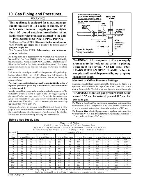
Install a ground joint union <strong>and</strong> manual shut-off valve upstream of the<br />
unit control system, as shown in Figure 8. The 1/8" plugged tapping in<br />
the shut-off valve provides connection for supply line pressure test<br />
gauge. The National Fuel Gas Code requires the installation of a trap<br />
with a minimum 3" drip leg. Local codes may require a minimum drip<br />
leg longer than 3" (typically 6").<br />
Gas connection sizes are included in the Dimensional Tables in Paragraph<br />
3. After all connections are made, disconnect the pilot supply at<br />
the control valve <strong>and</strong> bleed the system of air. Reconnect the pilot line<br />
<strong>and</strong> leak-test all connections by brushing on a soap solution.<br />
Sizing a Gas Supply Line<br />
Form 436, Page 10<br />
Figure 8 - Supply<br />
Piping Connection<br />
WARNING: All components of a gas supply<br />
system must be leak tested prior to placing<br />
equipment in service. NEVER TEST FOR<br />
LEAKS WITH AN OPEN FLAME. Failure to<br />
comply could result in personal injury, property<br />
damage or death.<br />
Manifold or Orifice Pressure Settings<br />
Measuring manifold gas pressure cannot be done until the heater is in<br />
operation. It is included in the steps of the "Check-Test-Start" procedure<br />
in Paragraph 24. The following warnings <strong>and</strong> instructions apply.<br />
WARNING: Manifold gas pressure must never<br />
exceed 3.5" w.c. for natural gas <strong>and</strong> 10" w.c. for<br />
propane gas.<br />
For Natural Gas: Manifold gas pressure is regulated by the combination<br />
valve to 3.5" w.c. Inlet pressure to the valve must be a minimum of<br />
5" w.c. or as noted on the rating plate <strong>and</strong> a maximum of 14" w.c.<br />
For Propane Gas: Manifold gas pressure is regulated by the combination<br />
valve to 10" w.c. Inlet pressure to the valve must be a minimum of<br />
11" w.c. <strong>and</strong> a maximum of 14" w.c.<br />
C apac ity of P iping<br />
Cubic Feet per Hour based on 0.3" w.c. Pressure Drop<br />
Sp ecific G ravity for N atural G as -- 0.6 (N atural G as -- 1000 BT U /Cubic Ft)<br />
Specific Gravity for Propane Gas -- 1.6 (Propane Gas -- 2550 BTU/Cubic Ft)<br />
Length Diameter of Pipe<br />
of 1/2" 3/4" 1" 1-1/4" 1-1/2" 2"<br />
Pip e Natu ral Pro p an e Natu ral Pro p an e Natu ral Pro p an e Natu ral Pro p an e Natu ral Pro p an e Natu ral Pro p an e<br />
20' 92 56 190 116 350 214 730 445 1100 671 2100 1281<br />
30' 73 45 152 93 285 174 590 360 890 543 1650 1007<br />
40' 63 38 130 79 245 149 500 305 760 464 1450 885<br />
50' 56 34 115 70 215 131 440 268 670 409 1270 775<br />
60' 50 31 105 64 195 119 400 244 610 372 1105 674<br />
70' 46 28 96 59 180 110 370 226 560 342 1050 641<br />
80' 43 26 90 55 170 104 350 214 530 323 990 604<br />
90' 40 24 84 51 160 98 320 195 490 299 930 567<br />
100' 38 23 79 48 150 92 305 186 460 281 870 531<br />
125' 34 21 72 44 130 79 275 168 410 250 780 476<br />
150' 31 19 64 39 120 73 250 153 380 232 710 433<br />
175' 28 17 59 36 110 67 225 137 350 214 650 397<br />
200' 26 16 55 34 100 61 210 128 320 195 610 372<br />
N ote: W hen siz ing sup p ly lines, consider p ossibilities of future exp ansion <strong>and</strong> increased requirem ents.<br />
Refer to National Fuel Gas Code for additional information on line sizing.