GENERAL Model FE and BE - Geisel
GENERAL Model FE and BE - Geisel
GENERAL Model FE and BE - Geisel
- TAGS
- model
- geisel
- www.gogeisel.com

You also want an ePaper? Increase the reach of your titles
YUMPU automatically turns print PDFs into web optimized ePapers that Google loves.
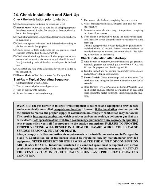
24. Check Installation <strong>and</strong> Start-Up<br />
Check the installation prior to start-up: 5. Thermostat calls for heat, energizing the venter motor.<br />
o Check suspension. Unit must be secure <strong>and</strong> level.<br />
o Blower <strong>Model</strong> - Check to be sure that all shipping supports<br />
have been removed. Rubber feet must be on the motor bracket<br />
bolts. See Paragraph 4.<br />
o Check clearances from combustibles. Requirements are shown<br />
in Paragraph 6.<br />
o Check vent system to be sure that it is installed according to<br />
the instructions in Paragraph 9.<br />
o Check piping for leaks <strong>and</strong> proper gas line pressure. Bleed<br />
gas lines of trapped air. See paragraph 10.<br />
o Check electrical wiring. Be sure all wire gauges are as recommended.<br />
A service disconnect switch should be used.<br />
Verify that fusing or circuit breakers are adequate for the load<br />
use.<br />
o Check that any field-installed options have been included in<br />
the installation.<br />
o Blower <strong>Model</strong> - Check belt tension. See Paragraph 14.<br />
Start-Up -- Typical Operating Sequence:<br />
1. Set thermostat at lowest setting.<br />
2. Turn on main <strong>and</strong> pilot manual gas valves.<br />
3. Turn on the power to the unit.<br />
4. Set the thermostat to desired setting.<br />
6. Venter pressure switch closes, firing the unit, after pilot proving<br />
sequence.<br />
7. Fan control senses heat exchanger temperature, energizing<br />
the fan or blower motor.<br />
8. If the flame is extinguished during the main burner operation,<br />
the safety switch closes the main valve <strong>and</strong> recycles the<br />
spark gap.<br />
On units equipped with lockout device, if the pilot is not established<br />
within 120 seconds, the unit locks out <strong>and</strong> must be<br />
reset by interrupting power to the control circuit. (See lighting<br />
instructions on the heater.)<br />
Check installation after start-up:<br />
o With the unit in operation, measure manifold gas pressure.<br />
Manifold pressure for natural gas should be 3.5" w.c. <strong>and</strong><br />
10" w.c. for propane gas. See Paragraph 10.<br />
o Turn the unit off <strong>and</strong> on, pausing two minutes between each<br />
cycle. Observe for smooth ignition.<br />
o Blower <strong>Model</strong> - Check motor amps with an amp meter. The<br />
maximum amp rating on the motor nameplate must not be<br />
exceeded.<br />
o Place 'Owner's Envelope" containing Limited Warranty Card,<br />
this booklet, <strong>and</strong> any optional information in an accessible<br />
location near the heater. Follow the instructions on the envelope.<br />
DANGER: The gas burner in this gas-fired equipment is designed <strong>and</strong> equipped to provide safe<br />
<strong>and</strong> economically controlled complete combustion. However, if the installation does not permit<br />
the burner to receive the proper supply of combustion air, complete combustion may not occur.<br />
The result is incomplete combustion which produces carbon monoxide, a poisonous gas that can<br />
cause death. Safe operation of indirect-fired gas burning equipment requires a properly operating<br />
vent system which vents all flue products to the outside atmosphere. FAILURE TO PROVIDE<br />
PROPER VENTING WILL RESULT IN A HEALTH HAZARD WHICH COULD CAUSE<br />
SERIOUS PERSONAL INJURY OR DEATH.<br />
Always comply with the combustion air requirements in the installation codes <strong>and</strong> in Paragraphs<br />
6 <strong>and</strong> 7. Combustion air at the burner should be regulated only by manufacturer-provided<br />
equipment. NEVER RESTRICT OR OTHERWISE ALTER THE SUPPLY OF COMBUSTION<br />
AIR TO ANY HEATER. Indoor units installed in a confined space must be supplied with air for<br />
combustion as required by Code <strong>and</strong> in Paragraph 7 of this heater installation manual. MAINTAIN<br />
THE VENT SYSTEM IN STRUCTURALLY SOUND AND PROPERLY OPERATING<br />
CONDITION.<br />
Mfg P/N 98807 Rev 8, Page 19