GENERAL Model FE and BE - Geisel
GENERAL Model FE and BE - Geisel
GENERAL Model FE and BE - Geisel
- TAGS
- model
- geisel
- www.gogeisel.com

You also want an ePaper? Increase the reach of your titles
YUMPU automatically turns print PDFs into web optimized ePapers that Google loves.
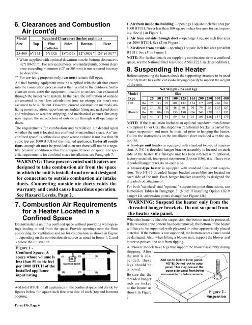
6. Clearances <strong>and</strong> Combustion<br />
Air (cont'd)<br />
<strong>Model</strong> Required Clearances (inches <strong>and</strong> mm)<br />
Size Top Flue Sides Bottom Rear<br />
Collector<br />
25-400 6"(152) 6"(152) 18"(457) 12"(305) * 24" (610)**<br />
* When supplied with optional downturn nozzle, bottom clearance is<br />
42"(1067mm). For service purposes, on st<strong>and</strong>ard units, bottom clearance<br />
exceeding minimum (12" or 305mm) is not required but may<br />
be desirable.<br />
** For servicing purposes only, rear must remain full open.<br />
All fuel-burning equipment must be supplied with the air that enters<br />
into the combustion process <strong>and</strong> is then vented to the outdoors. Sufficient<br />
air must enter the equipment location to replace that exhausted<br />
through the heater vent system. In the past, the infiltration of outside<br />
air assumed in heat loss calculations (one air change per hour) was<br />
assumed to be sufficient. However, current construction methods utilizing<br />
more insulation, vapor barriers, tighter fitting <strong>and</strong> gasketed doors<br />
<strong>and</strong> windows or weather-stripping, <strong>and</strong> mechanical exhaust fans may<br />
now require the introduction of outside air through wall openings or<br />
ducts.<br />
The requirements for combustion <strong>and</strong> ventilation air depend upon<br />
whether the unit is located in a confined or unconfined space. An "unconfined<br />
space" is defined as a space whose volume is not less than 50<br />
cubic feet per 1000 BTUH of the installed appliance. Under all conditions,<br />
enough air must be provided to ensure there will not be a negative<br />
pressure condition within the equipment room or space. For specific<br />
requirements for confined space installation, see Paragraph 7.<br />
WARNING: These power-vented unit heaters are<br />
designed to take combustion air from the space<br />
in which the unit is installed <strong>and</strong> are not designed<br />
for connection to outside combustion air intake<br />
ducts. Connecting outside air ducts voids the<br />
warranty <strong>and</strong> could cause hazardous operation.<br />
See Hazard Levels, Page 2.<br />
7. Combustion Air Requirements<br />
for a Heater Located in a<br />
Confined Space<br />
Do not install a unit in a confined space without providing wall openings<br />
leading to <strong>and</strong> from the space. Provide openings near the floor<br />
<strong>and</strong> ceiling for ventilation <strong>and</strong> air for combustion as shown in Figure<br />
1, depending on the combustion air source as noted in Items 1, 2, <strong>and</strong><br />
3 below the illustration.<br />
Figure 1 -<br />
Confined Space: A<br />
space whose volume is<br />
less than 50 cubic feet<br />
per 1000 BTUH of the<br />
installed appliance<br />
input rating<br />
Add total BTUH of all appliances in the confined space <strong>and</strong> divide by<br />
figures below for square inch free area size of each (top <strong>and</strong> bottom)<br />
opening.<br />
Form 436, Page 6<br />
1. Air from inside the building -- openings 1 square inch free area per<br />
1000 BTUH. Never less than 100 square inches free area for each opening.<br />
See (1) in Figure 1.<br />
2. Air from outside through duct -- openings 1 square inch free area<br />
per 2000 BTUH. See (2) in Figure 1.<br />
3. Air direct from outside -- openings 1 square inch free area per 4000<br />
BTUH. See (3) in Figure 1.<br />
NOTE: For further details on supplying combustion air to a confined<br />
space, see the National Fuel Gas Code ANSI Z223.1a (latest edition ).<br />
8. Suspending the Heater<br />
Before suspending the heater, check the supporting structure to be used<br />
to verify that it has sufficient load-carrying capacity to support the weight<br />
of the unit.<br />
Net Weight (lbs <strong>and</strong> kg)<br />
<strong>Model</strong> Size<br />
Type 25 50 75 100 125 165 200 250 300 400<br />
Fan lbs 76 83 92 101 132 154 175 209 226 281<br />
kg 34 38 42 46 60 70 79 95 103 127<br />
Blower lbs 97 104 118 130 180 206 240 278 301 395<br />
kg 44 47 54 59 82 93 109 126 137 179<br />
NOTE: If the installation includes an optional stepdown transformer<br />
kit (Option CF or CG), the stepdown transformer bracket is part of the<br />
heater suspension <strong>and</strong> must be installed prior to hanging the heater.<br />
Follow the instructions on the installation sheet included with the option<br />
kit.<br />
A fan-type unit heater is equipped with st<strong>and</strong>ard two-point suspension.<br />
A 3/8-16 threaded hanger bracket assembly is located on each<br />
side of the heater. If a fan-type unit has been ordered with optional,<br />
factory-installed, four-point suspension (Option BJ6), it will have two<br />
threaded hanger brackets on each side.<br />
A blower-type heater is equipped with st<strong>and</strong>ard four-point suspension.<br />
Two 3/8-16 threaded hanger bracket assemblies are located on<br />
each side of the unit. Each hanger bracket assembly is designed for<br />
threaded rod attachment.<br />
For both "st<strong>and</strong>ard" <strong>and</strong> "optional" suspension point dimensions, see<br />
Dimension Tables in Paragraph 3. (Note: If installing Option CK19<br />
hanger kit, suspension points change; see Figure 4B.)<br />
WARNING: Suspend the heater only from the<br />
threaded hanger brackets. Do not suspend from<br />
the heater side panel.<br />
When the heater is lifted for suspension, the bottom must be protected.<br />
If the wooden crate bottom has been removed, the bottom of the heater<br />
will have to be supported with plywood or other appropriately placed<br />
material. If the bottom is not supported, the bottom access panel could<br />
be damaged. Also, when lifting a blower unit, support the blower <strong>and</strong><br />
motor to prevent the unit from tipping.<br />
All blower models have legs that support the blower assembly during<br />
shipping. After<br />
the unit is suspended,<br />
these<br />
legs should be<br />
removed.<br />
Be sure that the<br />
threaded hanger<br />
rods are locked<br />
to the heater as<br />
shown in Figure<br />
2.<br />
Figure 2 -<br />
Suspension