GENERAL Model FE and BE - Geisel
GENERAL Model FE and BE - Geisel
GENERAL Model FE and BE - Geisel
- TAGS
- model
- geisel
- www.gogeisel.com

You also want an ePaper? Increase the reach of your titles
YUMPU automatically turns print PDFs into web optimized ePapers that Google loves.
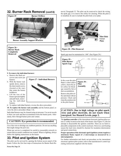
32. Burner Rack Removal (cont'd)<br />
Figure 25<br />
Figure 26 -<br />
Burner Rack<br />
Completely<br />
Removed<br />
9. To remove the individual burners:<br />
a. Remove the flash carryover<br />
(one screw per<br />
burner).<br />
Figure 27 - Individual Burners<br />
b. With the burner rack<br />
upside down, remove<br />
the sheet metal screws<br />
(located at the rear)<br />
that retain the burner<br />
holddown.<br />
c. Lift the rear of the<br />
burner upward slightly<br />
<strong>and</strong> pull back, removing<br />
the individual<br />
burners.<br />
d. To replace individual burners, reverse the above procedure.<br />
10. To replace the burner rack assembly <strong>and</strong> the bottom panel, reverse<br />
the above procedure (Steps 1-8).<br />
Individual burners may be cleaned using air pressure. Use an air nozzle<br />
to blow out scale <strong>and</strong> dust accumulation from the burner ports. Alternately,<br />
blow through burner ports <strong>and</strong> venturi.<br />
Form 436, Page 24<br />
Burner Orifices<br />
Burner Assembly Support Brackets<br />
CAUTION: Eye protection is recommended.<br />
Use a fine wire to dislodge any stubborn particles. Do not use anything<br />
that might change the port size.<br />
When any service is completed, be careful to reassemble correctly to<br />
ensure that no unsafe conditions are created. When re-lighting, always<br />
follow the lighting instructions on the heater.<br />
33. Pilot <strong>and</strong> Ignition System<br />
The pilot can be serviced by opening the bottom access panel of the<br />
heater. Follow the first four steps of instructions for Burner Rack Re-<br />
moval, Paragraph 32. The pilot can be removed to check the wiring,<br />
the spark gap, or to remove the orifice for cleaning. When the pilot is<br />
re-installed, be sure to include the pilot hole cover plate.<br />
Figure 28 - Pilot Removal<br />
Spark gap must be maintained to .100". (See Figure 29.)<br />
Figure 29 -<br />
Pilot Burner<br />
Spark Gap<br />
In the event the pilot<br />
flame is short <strong>and</strong>/or<br />
yellow, check the pilot<br />
orifice for blockage<br />
caused by lint or<br />
dust accumulation.<br />
Remove the pilot orifice<br />
<strong>and</strong> clean with air<br />
pressure. Check <strong>and</strong><br />
clean the aeration slot<br />
in the pilot burner.<br />
Figure 30 -<br />
Pilot<br />
Assembly<br />
Pilot Hole<br />
Cover<br />
Plate<br />
CAUTION: Due to high voltage on pilot spark<br />
wire <strong>and</strong> pilot electrode, do not touch when<br />
energized. See Hazard Levels, page 2.<br />
The ignition controller of the intermittent electronic ignition pilot system<br />
is visibly located on the back of the heater. (See Figure 31.) Do not<br />
attempt to disassemble the ignition controller. There are no field replaceable<br />
components in the control enclosure. However, each heating<br />
season the lead wires should be checked for insulation deterioration<br />
<strong>and</strong> good connections.<br />
Proper operation of the electronic spark ignition system requires a<br />
minimum flame signal of .2 microamps as measured by a<br />
microampmeter.<br />
For further information <strong>and</strong> check out procedure on the intermittent<br />
electronic ignition pilot system, refer to the manufacturer's control operating<br />
instructions supplied with the heater.