GENERAL Model FE and BE - Geisel
GENERAL Model FE and BE - Geisel
GENERAL Model FE and BE - Geisel
- TAGS
- model
- geisel
- www.gogeisel.com

You also want an ePaper? Increase the reach of your titles
YUMPU automatically turns print PDFs into web optimized ePapers that Google loves.
9. Venting (cont'd)<br />
Venter Outlet Attachment Requirements:<br />
• If the pipe used in the vent run is larger than the diameter of the<br />
venter outlet (See Vent Length Table 2), make the transition at<br />
the venter outlet.<br />
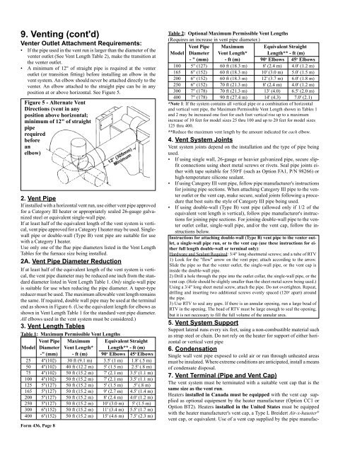
• A minimum of 12" of straight pipe is required at the venter<br />
outlet (or transition fitting) before installing an elbow in the<br />
vent system. An elbow should never be attached directly to the<br />
venter. An elbow attached to the straight pipe can be in any<br />
position at or above horizontal. See Figure 5.<br />
Figure 5 - Alternate Vent<br />
Directions (vent in any<br />
position above horizontal;<br />
minimum of 12" of straight<br />
pipe<br />
required<br />
before<br />
an<br />
elbow)<br />
2. Vent Pipe<br />
If installed with a horizontal vent run, use either vent pipe approved<br />
for a Category III heater or appropriately sealed 26-gauge galvanized<br />
steel or equivalent single-wall pipe.<br />
If at least half of the equivalent length of the vent system is vertical,<br />
vent pipe approved for a Category I heater may be used. Singlewall<br />
pipe or double-wall (Type B) vent pipe are suitable for use<br />
with a Category I heater.<br />
Use only one of the flue pipe diameters listed in the Vent Length<br />
Tables for the furnace size being installed.<br />
2A. Vent Pipe Diameter Reduction<br />
If at least half of the equivalent length of the vent system is vertical,<br />
the vent pipe diameter may be reduced one inch from the st<strong>and</strong>ard<br />
diameter listed in Vent Length Table 1. Only single-wall pipe<br />
is suitable for use when reducing the pipe diameter. A taper-type<br />
reducer must be used. The maximum allowable vent length remains<br />
the same. If required, double wall pipe may be used at the terminal<br />
end as shown in Figure 6. (Use the equivalent length for elbows as<br />
shown in Vent Length Table 1 for the st<strong>and</strong>ard vent pipe diameter.<br />
All elbows used in the vent system must be considered.)<br />
3. Vent Length Tables<br />
Table 1: Maximum Permissible Vent Lengths<br />
Vent Pipe Maximum Equivalent Straight<br />
<strong>Model</strong> Diameter Vent Length* Length** - ft (m)<br />
-" (mm) - ft (m) 90o Elbows 45o Elbows<br />
25 4"(102) 30 ft (9.1 m) 3.5' (1 m) 1.8' (.5 m)<br />
50 4"(102) 40 ft (12.2 m) 5' (1.5 m) 2.5' (.8 m)<br />
75 4"(102) 50 ft (15.2 m) 7' (2.1 m) 3.5' (1.1 m)<br />
100 4"(102) 50 ft (15.2 m) 7' (2.1 m) 3.5' (1.1 m)<br />
125 5"(127) 50 ft (15.2 m) 5' (1.5 m) .5' (.8 m)<br />
165 5"(127) 50 ft (15.2 m) 9' (2.7 m) 4.5' (1.4 m)<br />
200 5"(127) 50 ft (15.2 m) 8' (2.4 m) 4.0' (1.2 m)<br />
250 5"(127) 50 ft (15.2 m) 10' (3.0 m) 5' (1.5 m)<br />
300 6"(152) 50 ft (15.2 m) 11' (3.4 m) 5.5' (1.7 m)<br />
400 6"(152) 50 ft (15.2 m) 15' (4.6 m) 7.5' (2.3 m)<br />
Form 436, Page 8<br />
Table 2: Optional Maximum Permissible Vent Lengths<br />
(Requires an increase in vent pipe diameter.)<br />
Vent Pipe Maximum Equivalent Straight<br />
<strong>Model</strong> Diameter Vent Length* Length** - ft (m)<br />
- " (mm) - ft (m) 90 o Elbows 45 o Elbows<br />
100 5" (127) 60 ft (18.3 m) 8' (2.4 m) 4.0' (1.2 m)<br />
165 6" (152) 60 ft (18.3 m) 10' (3.0 m) 5.0' (1.5 m)<br />
200 6" (152) 60 ft (18.3 m) 12' (3.7 m) 6.0' (1.8 m)<br />
250 6" (152) 70 ft (21.3 m) 8' (2.4 m) 4.0' (1.2 m)<br />
300 7" (178) 70 ft (21.3 m) 13' (4.0) 6.5' (2.0 m)<br />
400 7" (178) 90 ft (27.4 m) 14' (4.3) 7.0' (2.1)<br />
*Note 1: If the system contains all vertical pipe or a combination of horizontal<br />
<strong>and</strong> vertical vent pipe, the Maximum Permissible Vent Length shown in Tables 1<br />
<strong>and</strong> 2 may be increased one foot for each foot vertical rise up to a maximum<br />
increase of 10 feet for model sizes 25 thru 100 <strong>and</strong> up to 20 feet for model sizes<br />
125 thru 400.<br />
**Reduce the maximum vent length by the amount indicated for each elbow.<br />
4. Vent System Joints<br />
Vent system joints depend on the installation <strong>and</strong> the type of pipe being<br />
used.<br />
• If using single wall, 26-gauge or heavier galvanized pipe, secure slipfit<br />
connections using sheet metal screws or rivets. Seal pipe joints either<br />
with tape suitable for 550 o F (such as Option FA1, P/N 98266) or<br />
high-temperature silicone sealant.<br />
• If using Category III vent pipe, follow pipe manufacturer's instructions<br />
for joining pipe sections. When attaching Category III pipe to the venter<br />
outlet or the vent cap, make secure, sealed joints following a procedure<br />
that best suits the style of Category III pipe being used.<br />
• If using double-wall (Type B) vent pipe (allowed only if 1/2 of the<br />
equivalent vent length is vertical), follow pipe manufacturer's instructions<br />
for joining pipe sections. For joining double-wall pipe to the venter<br />
outlet collar, single-wall pipe, <strong>and</strong>/or the vent cap, follow the instructions<br />
below.<br />
Instructions for attaching double-wall (Type B) vent pipe to the venter outlet,<br />
a single-wall pipe run, or to the vent cap (use these instructions for either<br />
full length double-wall or terminal only):<br />
Hardware <strong>and</strong> Sealant Required: 3/4" long sheetmetal screws; <strong>and</strong> a tube of RTV<br />
1) Look for the "flow" arrow on the vent pipe; attach according to the arrow.<br />
Slide the pipe so that the venter outlet, the single-wall pipe, or the vent cap is<br />
inside the double-wall pipe.<br />
2) Drill a hole through the pipe into the outlet collar, the single-wall pipe, or the<br />
vent cap. (Hole should be slightly smaller than the sheet metal screw being used.)<br />
Using a 3/4" long sheet metal screw, attach the pipe. Do not overtighten. Repeat,<br />
drilling <strong>and</strong> inserting two additional screws evenly spaced (120 o apart) around<br />
the pipe.<br />
3) Use RTV to seal any gaps. If there is an annular opening, run a large bead of<br />
RTV in the opening. The bead of RTV must be large enough to seal the opening,<br />
but it is not necessary to fill the full volume of the annular area.<br />
5. Vent System Support<br />
Support lateral runs every six feet, using a non-combustible material such<br />
as strap steel or chain. Do not rely on the heater for support of either horizontal<br />
or vertical vent pipe<br />
6. Condensation<br />
Single wall vent pipe exposed to cold air or run through unheated areas<br />
must be insulated. Where extreme conditions are anticipated, install a means<br />
of condensate disposal.<br />
7. Vent Terminal (Pipe <strong>and</strong> Vent Cap)<br />
The vent system must be terminated with a suitable vent cap that is the<br />
same size as the vent run.<br />
Heaters installed in Canada must be equipped with the vent cap supplied<br />
as optional equipment by the heater manufacturer (Option CC1 or<br />
Option BT2). Heaters installed in the United States must be equipped<br />
with the heater manufacturer's vent cap, a Type L Breidert Air-x-hauster ®<br />
vent cap, or equivalent. Use of a vent cap supplied by the pipe manufac-