GENERAL Model FE and BE - Geisel
GENERAL Model FE and BE - Geisel
GENERAL Model FE and BE - Geisel
- TAGS
- model
- geisel
- www.gogeisel.com

Create successful ePaper yourself
Turn your PDF publications into a flip-book with our unique Google optimized e-Paper software.
12. Thermostat Connections (cont'd)<br />
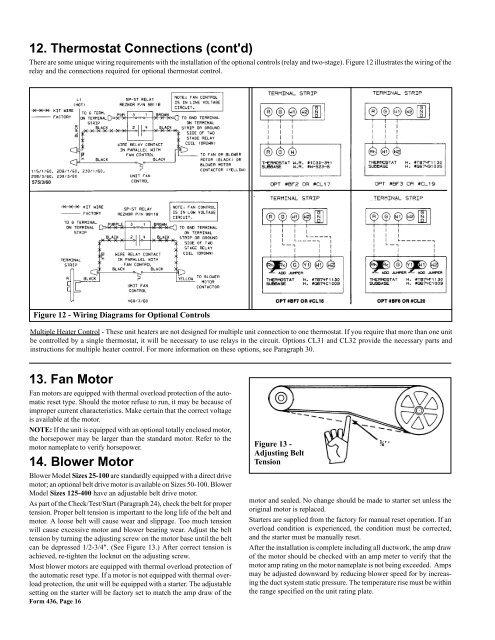
There are some unique wiring requirements with the installation of the optional controls (relay <strong>and</strong> two-stage). Figure 12 illustrates the wiring of the<br />
relay <strong>and</strong> the connections required for optional thermostat control.<br />
575/3/60<br />
Figure 12 - Wiring Diagrams for Optional Controls<br />
Multiple Heater Control - These unit heaters are not designed for multiple unit connection to one thermostat. If you require that more than one unit<br />
be controlled by a single thermostat, it will be necessary to use relays in the circuit. Options CL31 <strong>and</strong> CL32 provide the necessary parts <strong>and</strong><br />
instructions for multiple heater control. For more information on these options, see Paragraph 30.<br />
13. Fan Motor<br />
Fan motors are equipped with thermal overload protection of the automatic<br />
reset type. Should the motor refuse to run, it may be because of<br />
improper current characteristics. Make certain that the correct voltage<br />
is available at the motor.<br />
NOTE: If the unit is equipped with an optional totally enclosed motor,<br />
the horsepower may be larger than the st<strong>and</strong>ard motor. Refer to the<br />
motor nameplate to verify horsepower.<br />
14. Blower Motor<br />
Blower <strong>Model</strong> Sizes 25-100 are st<strong>and</strong>ardly equipped with a direct drive<br />
motor; an optional belt drive motor is available on Sizes 50-100. Blower<br />
<strong>Model</strong> Sizes 125-400 have an adjustable belt drive motor.<br />
As part of the Check/Test/Start (Paragraph 24), check the belt for proper<br />
tension. Proper belt tension is important to the long life of the belt <strong>and</strong><br />
motor. A loose belt will cause wear <strong>and</strong> slippage. Too much tension<br />
will cause excessive motor <strong>and</strong> blower bearing wear. Adjust the belt<br />
tension by turning the adjusting screw on the motor base until the belt<br />
can be depressed 1/2-3/4". (See Figure 13.) After correct tension is<br />
achieved, re-tighten the locknut on the adjusting screw.<br />
Most blower motors are equipped with thermal overload protection of<br />
the automatic reset type. If a motor is not equipped with thermal overload<br />
protection, the unit will be equipped with a starter. The adjustable<br />
setting on the starter will be factory set to match the amp draw of the<br />
Form 436, Page 16<br />
Figure 13 -<br />
Adjusting Belt<br />
Tension<br />
motor <strong>and</strong> sealed. No change should be made to starter set unless the<br />
original motor is replaced.<br />
Starters are supplied from the factory for manual reset operation. If an<br />
overload condition is experienced, the condition must be corrected,<br />
<strong>and</strong> the starter must be manually reset.<br />
After the installation is complete including all ductwork, the amp draw<br />
of the motor should be checked with an amp meter to verify that the<br />
motor amp rating on the motor nameplate is not being exceeded. Amps<br />
may be adjusted downward by reducing blower speed for by increasing<br />
the duct system static pressure. The temperature rise must be within<br />
the range specified on the unit rating plate.