STAR Service News Missed an issue? - Toyota Parts & Service
STAR Service News Missed an issue? - Toyota Parts & Service
STAR Service News Missed an issue? - Toyota Parts & Service

Create successful ePaper yourself
Turn your PDF publications into a flip-book with our unique Google optimized e-Paper software.
TOYOTA TECHNICAL<br />
voltage drop reading (do not<br />
cr<strong>an</strong>k the engine for more th<strong>an</strong> 10<br />
seconds at a time). 0.2V or less is<br />
acceptable resist<strong>an</strong>ce. More th<strong>an</strong><br />
0.2V is excessive resist<strong>an</strong>ce. If excessive<br />
resist<strong>an</strong>ce is found, isolate<br />
the cause, repair the fault <strong>an</strong>d<br />
re-test the voltage drop. Excessive<br />
resist<strong>an</strong>ce in this case could<br />
be caused by a damaged battery<br />
cable, poor connection at the<br />
battery <strong>an</strong>d/or starter terminal<br />
or poor connection between the<br />
starter case <strong>an</strong>d the engine block.<br />
MAGNETIC SWITCH<br />
This test measures the voltage<br />
drop across the starter’s magnetic<br />
switch. (NOTE: Starters with<br />
pl<strong>an</strong>etary gear reduction do not<br />
feature a magnetic switch).<br />
Connect the meter’s red lead<br />
to starter terminal C <strong>an</strong>d connect<br />
the meter’s black lead to starter<br />
terminal 30. Cr<strong>an</strong>k the engine <strong>an</strong>d<br />
note the voltage drop (again, do<br />
not cr<strong>an</strong>k the engine for more<br />
th<strong>an</strong> 10 seconds at a time). 0.3V or<br />
less is acceptable resist<strong>an</strong>ce. More<br />
th<strong>an</strong> 0.3V indicates excessive<br />
resist<strong>an</strong>ce. If resist<strong>an</strong>ce is excessive,<br />
isolate the cause, repair <strong>an</strong>d<br />
re-test. NOTE: A faulty magnetic<br />
switch could cause excessive<br />
resist<strong>an</strong>ce.<br />
<strong>STAR</strong>TER CONTROL<br />
CIRCUIT<br />
Excessive resist<strong>an</strong>ce in the starter<br />
control circuit c<strong>an</strong> reduce the<br />
voltage available to the magnetic<br />
switch. Symptoms include nonengagement<br />
of the pinion gear<br />
<strong>an</strong>d only partial gear engagement.<br />
The areas where excessive<br />
resist<strong>an</strong>ce c<strong>an</strong> occur include the<br />
ST contacts of the ignition switch,<br />
neutral start switch/clutch start<br />
switch <strong>an</strong>d circuit wiring <strong>an</strong>d connections.<br />
Test for excessive resist<strong>an</strong>ce in<br />
the starter control circuit. Connect<br />
the meter’s red lead to the<br />
positive (+) battery terminal <strong>an</strong>d<br />
connect the black lead to terminal<br />
50 on the starter motor. On a vehicle<br />
equipped with <strong>an</strong> automatic<br />
tr<strong>an</strong>smission, put the shift selector<br />
in Park or Neutral. If equipped<br />
with a m<strong>an</strong>ual tr<strong>an</strong>smission,<br />
depress the clutch pedal.<br />
Cr<strong>an</strong>k the engine (do not<br />
cr<strong>an</strong>k for more th<strong>an</strong> 10 seconds<br />
at a time) <strong>an</strong>d note the voltage<br />
drop. 1.2V or less is acceptable.<br />
More th<strong>an</strong> 1.2V is <strong>an</strong> indication<br />
of excessive resist<strong>an</strong>ce. Measure<br />
the voltage drop across the<br />
ignition switch <strong>an</strong>d the neutral<br />
start/clutch switch.<br />
0.1V or less is acceptable.<br />
More th<strong>an</strong> 0.1V<br />
indicates excessive<br />
resist<strong>an</strong>ce.<br />
If excessive resist<strong>an</strong>ce<br />
is found, isolate<br />
the problem, repair<br />
<strong>an</strong>d re-test.<br />
As you c<strong>an</strong> see,<br />
testing for voltage<br />
drop c<strong>an</strong> be a useful<br />
diagnostic tool.<br />
As mentioned earlier with<br />
regard to fl ash reprogramming<br />
<strong>an</strong> ECM, maintaining a steady<br />
voltage is critical to avoid ECM<br />
damage. An excessive voltage<br />
drop c<strong>an</strong> certainly contribute to<br />
reprogramming errors <strong>an</strong>d damage<br />
to a control unit. This helps to<br />
illustrate why use of the GR8 battery<br />
station is so helpful, since it<br />
maintains a const<strong>an</strong>t 13.5V during<br />
fl ash reprogramming.<br />
CURRENT FLOW<br />
Current is the term used to<br />
describe the fl ow of electrons<br />
through the circuit. It is this fl ow<br />
of electrons that performs the<br />
“work” in the circuit. The unit for<br />
measuring the amount of current<br />
fl ow is the ampere or amp (A).<br />
One amp equals 6.28 billion billion<br />
electrons per second fl owing<br />
through a circuit.<br />
Current will only fl ow if there<br />
is a complete circuit (continuity)<br />
between a source of higher voltage<br />
(power) <strong>an</strong>d a lower voltage<br />
(ground). Voltage is the pressure<br />
that pushes the electrons through<br />
the circuit, <strong>an</strong>d Amperes is a measure<br />
of the number of electrons<br />
fl owing through the circuit.<br />
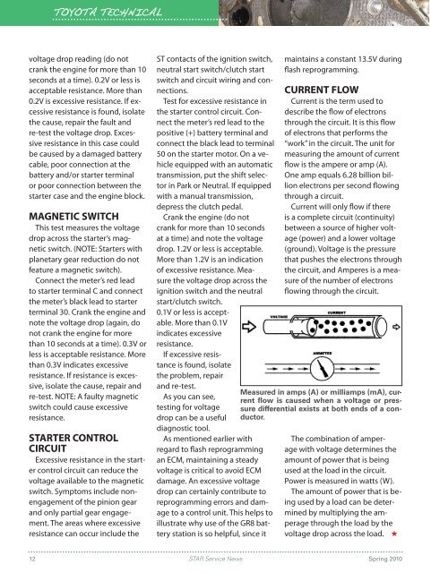
Measured in amps (A) or milliamps (mA), current<br />
fl ow is caused when a voltage or pressure<br />
differential exists at both ends of a conductor.<br />
The combination of amperage<br />
with voltage determines the<br />
amount of power that is being<br />
used at the load in the circuit.<br />
Power is measured in watts (W).<br />
The amount of power that is being<br />
used by a load c<strong>an</strong> be determined<br />
by multiplying the amperage<br />
through the load by the<br />
voltage drop across the load. ★<br />
12 <strong>STAR</strong> <strong>Service</strong> <strong>News</strong><br />
Spring 2010